US5882691A - automatic dry wall compound applicator - Google Patents
automatic dry wall compound applicator Download PDFInfo
- Publication number
- US5882691A US5882691A US08/811,768 US81176897A US5882691A US 5882691 A US5882691 A US 5882691A US 81176897 A US81176897 A US 81176897A US 5882691 A US5882691 A US 5882691A
- Authority
- US
- United States
- Prior art keywords
- applicator
- head
- dry wall
- loading
- wall compound
- Prior art date
- Legal status (The legal status is an assumption and is not a legal conclusion. Google has not performed a legal analysis and makes no representation as to the accuracy of the status listed.)
- Expired - Lifetime
Links
Images


Classifications
-
- E—FIXED CONSTRUCTIONS
- E04—BUILDING
- E04F—FINISHING WORK ON BUILDINGS, e.g. STAIRS, FLOORS
- E04F21/00—Implements for finishing work on buildings
- E04F21/02—Implements for finishing work on buildings for applying plasticised masses to surfaces, e.g. plastering walls
- E04F21/06—Implements for applying plaster, insulating material, or the like
-
- B—PERFORMING OPERATIONS; TRANSPORTING
- B05—SPRAYING OR ATOMISING IN GENERAL; APPLYING FLUENT MATERIALS TO SURFACES, IN GENERAL
- B05C—APPARATUS FOR APPLYING FLUENT MATERIALS TO SURFACES, IN GENERAL
- B05C17/00—Hand tools or apparatus using hand held tools, for applying liquids or other fluent materials to, for spreading applied liquids or other fluent materials on, or for partially removing applied liquids or other fluent materials from, surfaces
- B05C17/002—Hand tools or apparatus using hand held tools, for applying liquids or other fluent materials to, for spreading applied liquids or other fluent materials on, or for partially removing applied liquids or other fluent materials from, surfaces with feed system for supplying material from an external source; Supply controls therefor
- B05C17/003—Hand tools or apparatus using hand held tools, for applying liquids or other fluent materials to, for spreading applied liquids or other fluent materials on, or for partially removing applied liquids or other fluent materials from, surfaces with feed system for supplying material from an external source; Supply controls therefor with means for filling or refilling the hand tool container
-
- B—PERFORMING OPERATIONS; TRANSPORTING
- B05—SPRAYING OR ATOMISING IN GENERAL; APPLYING FLUENT MATERIALS TO SURFACES, IN GENERAL
- B05C—APPARATUS FOR APPLYING FLUENT MATERIALS TO SURFACES, IN GENERAL
- B05C17/00—Hand tools or apparatus using hand held tools, for applying liquids or other fluent materials to, for spreading applied liquids or other fluent materials on, or for partially removing applied liquids or other fluent materials from, surfaces
- B05C17/005—Hand tools or apparatus using hand held tools, for applying liquids or other fluent materials to, for spreading applied liquids or other fluent materials on, or for partially removing applied liquids or other fluent materials from, surfaces for discharging material from a reservoir or container located in or on the hand tool through an outlet orifice by pressure without using surface contacting members like pads or brushes
- B05C17/015—Hand tools or apparatus using hand held tools, for applying liquids or other fluent materials to, for spreading applied liquids or other fluent materials on, or for partially removing applied liquids or other fluent materials from, surfaces for discharging material from a reservoir or container located in or on the hand tool through an outlet orifice by pressure without using surface contacting members like pads or brushes with pneumatically or hydraulically actuated piston or the like
-
- B—PERFORMING OPERATIONS; TRANSPORTING
- B05—SPRAYING OR ATOMISING IN GENERAL; APPLYING FLUENT MATERIALS TO SURFACES, IN GENERAL
- B05C—APPARATUS FOR APPLYING FLUENT MATERIALS TO SURFACES, IN GENERAL
- B05C17/00—Hand tools or apparatus using hand held tools, for applying liquids or other fluent materials to, for spreading applied liquids or other fluent materials on, or for partially removing applied liquids or other fluent materials from, surfaces
- B05C17/005—Hand tools or apparatus using hand held tools, for applying liquids or other fluent materials to, for spreading applied liquids or other fluent materials on, or for partially removing applied liquids or other fluent materials from, surfaces for discharging material from a reservoir or container located in or on the hand tool through an outlet orifice by pressure without using surface contacting members like pads or brushes
- B05C17/01—Hand tools or apparatus using hand held tools, for applying liquids or other fluent materials to, for spreading applied liquids or other fluent materials on, or for partially removing applied liquids or other fluent materials from, surfaces for discharging material from a reservoir or container located in or on the hand tool through an outlet orifice by pressure without using surface contacting members like pads or brushes with manually mechanically or electrically actuated piston or the like
- B05C17/0136—Hand tools or apparatus using hand held tools, for applying liquids or other fluent materials to, for spreading applied liquids or other fluent materials on, or for partially removing applied liquids or other fluent materials from, surfaces for discharging material from a reservoir or container located in or on the hand tool through an outlet orifice by pressure without using surface contacting members like pads or brushes with manually mechanically or electrically actuated piston or the like comprising an energy storing element, e.g. a spring, for exerting, e.g. when released, pressure on the material
Definitions
- This invention relates to dry wall taping and in particular to a machine for applying dry wall compound to joints and corners where dry wall tape and tape on corner beads is applied.
- a principal object of this invention is to provide a machine in which a manually operated pump injects dry wall compound into the applicator from a supply receptacle and a gas operated spring assembly is used to eject the dry wall compound through a nozzle on the applicator in a controlled manner without requiring intense physical force from the operator of the device.
- An automatic brake assembly allows loading of dry wall compound into the applicator, but acts automatically to prevent ejection of dry wall compound unless the brake is released by the operator.
- Another object is to provide an applicator which easily comes apart to facilitate cleaning the dry wall compound out of the applicator parts. Another object is to provide an applicator which can be placed in an upright position for easy "hands free” loading of dry wall compound into the applicator. Still another object is to provide an applicator that can be used for inside and outside corners as well as flat joints, and can be used for finish coating of dry wall compound as well as for first coats.
- the invention is embodied in a dry wall compound applicator comprising a main dry wall compound retaining cylinder having a dispensing and filing head on one end and a brake housing and handle receptacle on the other end.
- a nitrogen filled gas spring Inside the handle is a nitrogen filled gas spring whose actuating shaft extends into the cylinder and has a dispensing piston connected to its free end.
- a brake and brake release controls movement of the actuating shaft.
- a filler tube connects a dry wall compound receptacle to a fill valve in the head to allow a manually operated pump to fill dry wall compound into the cylinder and compress the gas spring.
- a valve on the dispensing end of the dispensing head is closed during filing of the cylinder and compression of the gas spring, but is open during controlled application of the dry wall compound.
- the brake controls operation of the gas spring so that when the brake is released and the valve opened, compound is dispensed from a universal applicator nozzle on the dispensing head.
- the brake automatically locks when filling is stopped at any stage during filling and also during dispensing, unless manually released by the operator.
- FIG. 1 is a fragmentary perspective view showing use of the applicator on a flat wall joint
- FIG. 2 is a view similar to FIG. 1 but showing use of the applicator on a corner joint;
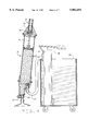
- FIG. 3 is a fragmentary vertical sectional view showing loading of dry wall compound into the applicator with the gas cylinder in elevation;
- FIG. 4 is a view similar to FIG. 3 but showing the applicator partially filled
- FIG. 5 is a fragmentary vertical sectional view showing the applicator in dispensing condition and the gas cylinder in elevation;
- FIG. 6 is a fragmentary vertical sectional view of the handle portion of the applicator with the gas cylinder in elevation;
- FIG. 7 is a perspective view of the brake mechanism
- FIG. 8 is a foreshortened fragmentary vertical sectional view of the applicator handle and brake mechanism with the gas cylinder in elevation;
- FIG. 9 is a foreshortened fragmentary vertical sectional view of the gas cylinder
- FIG. 10 is a fragmentary sectional view party in elevation of a modified filling assembly
- FIG. 11 is a fragmentary sectional view partly in elevation of the modification of FIG. 10 being moved into filling position.
- FIG. 12 is an enlarged vertical sectional view of the attachment of the fill ture to the application.
- FIGS. 1 and 2 show the dry wall compound dispensing device 10 in operation.
- the device 10 comprises a compound dispensing and filling nozzle assembly 11, a main compound retaining cylinder 12, a brake and handle housing 13, a handle 14, which contains a gas spring, and a brake release 15.
- FIG. 1 shows the use of the device 10 on a flat wall joint "J" and
- FIG. 2 shows its use on an inside corner "C".
- FIGS. 3 and 4 show the device 10 attached to a compound loading receptacle 16 by means of a fill tube 17.
- a support stand 18 attached to the receptacle 16 has a semi-circular cradle 29 which engages the outer surface of the cylinder 12 to help support the device 10 during filling.
- FIGS. 5, 6 and 9 also show the gas spring assembly 20 which is a standard article of commerce such as that sold by AVM, Inc. of Marion, S.C. under the name GGSX Gas Spring.
- the preferred gas spring has a 15-18" stroke and a force of about 60 pounds. The force can vary from about 40 to about 70 pounds.
- the rates of discharge can vary depending on the viscosity of the compound.
- the gas spring assembly 20 includes an actuating shaft 21 which extends outside a first end of the gas spring housing 22 through the brake and handle housing 13 into the interior of the compound cylinder 12.
- a compound dispensing head 25 Attached to the leading end of the shaft 21 is a compound dispensing head 25 which includes a set of flexible wiping fingers 26 to wipe the interior of the cylinder 12 and push the compound out of the cylinder 12 during operation.
- the fingers 26 are trifurcated with one finger 26a directed toward the interior of the cylinder 12, one finger 26b positioned perpendicular to the side wall of the cylinder 12, and the third finger 26c directed toward the dispensing end of the cylinder 12.
- the fingers 26 prevent the dry wall compound from getting behind the head during either filling or dispensing. This structure is shown in more detail in FIG. 5.
- a compressed air cylinder can be used as the gas spring assembly 20.
- the cylinder 12 preferably is made of a transparent plastic, such as polycarbonate, so that the operator can visually determine how much dry wall compound is in the cylinder 12.
- a cylinder front head 30 Attached to the front end of the cylinder 12 is a cylinder front head 30 which has an internal annular counterbore 31 to engage the front end of the cylinder 12 and an external annular lip 32 at the leading edge.
- the head 30 preferably is of aluminum and is secured to the cylinder 12 by a suitable adhesive.
- the head 30 also can be of a suitable plastic to reduce weight.
- the nozzle assembly 11 is comprised of two elements, a front nose 35 and a dispensing nozzle 36.
- Universal finishing heads or dry wall heads 36 can be adapted to be used as the nozzle 36. These are conventional in the industry and FIG. 1 shows a nozzle 36 which is hollow and has a dispensing opening 38.
- the nozzle 36 dispenses a layer of dry wall compound 37 approximately the same width as the dispensing opening 38 in the nozzle 36.
- the nozzle apex 39 has an internal spherical pocket 40 to accommodate a ball 41 on the leading edge of the nose 35.
- the pocket 40 and ball 41 define a ball joint assembly which allows universal pivoting of the nozzle 36 with respect to the rest of the device 10 to accommodate the user in applying dry wall to ceilings, walls, etc.
- the nozzle 36 is snapped onto the ball 41 to attach the nozzle 36 to the device 10.
- the nose 35 is hollow and tapers from rear to front. It preferably is made of aluminum and includes an annular rim 44 and a counterbore 45 at its larger rear end. The rim 44 is coextensive with the front head lip 32. A O-ring seal 46 fits in the counterbore 45 and seals the nose 35 to the cylinder 12.
- the nose 35 can be made of plastic to reduce weight.
- a quick release snap rim retainer 47 holds the rims 32 and 44 in assembled condition and permits quick and rapid removal of the nozzle 11 from the body 12 for cleaning.
- Another method of fastening the nozzle 11 to the body 12 is by a threaded connection.
- a loading boss 48 is positioned on the nose 35 adjacent to the rim 44 and is provided with a conventional spring loaded loading valve assembly which includes a valve retainer 49, a valve plate 50 and a valve spring 51.
- the loading boss 48 is provided with an external loading port 52 which is adapted to accommodate a loading nozzle 53 on the end of the fill tube 17. The nozzle 53 slides into the port 52 and is locked in place by engagement of locking shoulders 54 on the boss 48 and 55 on the nozzle 53.
- the ball joint and valve assembly 58 which includes the ball joint 41 previously described.
- the assembly 58 has a throughbore 59 which extends through the ball 41 and a ball valve seat 60 which retains a ball valve 61 which can be rotated by a handle and stem 62 into open or closed position.
- the ball valve 61 is closed during filling of the dispenser and open during application of dry wall compound.
- An alternative filling method is to provide a snap clamp on the free end of the fill tube 17 so that the fill tube 17 can be snapped onto the ball 41 and the device 10 is filled through the throughbore 59 of the assembly 58.
- the ball valve 61 is eliminated as seen in FIGS. 10 and 11.
- the need for a loading boss 48 and the associated port and valve also is eliminated. This modification will be described in more detail hereinafter.
- the housing 13 is comprised of two parts, the first of which is an annular ring 65 having a counterbore 66, which accommodates the cylinder 12, and an annular rim 67.
- the second part 68 has a boss 69 which fits inside the end of the cylinder 12, an annular rim 70 which engages the rim 67, and a tapered nose 71 which is provided with a counterbore 72 to accommodate the hollow handle 14.
- the second part 68 has a throughbore 73 provided with internal seals 74 to guide the gas spring shaft 21 into and out of the cylinder 12.
- a slot 75 is positioned in the top of the housing 13 and extends past the throughbore 73.
- a locking cam 76 which has a cam surface 77 positioned over the air spring shaft 21 (FIGS. 7 and 8).
- the cam 76 pivots freely rearwardly (arrow A in FIG. 7) to allow the gas spring shaft 21 to move into the gas spring, during loading of the cylinder 12.
- the cam 76 pivots in the forward direction ("B" in FIG. 7) and the cam surface 77 engages the shaft 21 to lock the gas spring 20 in inoperative position.
- a lock support plate 80 is secured in the slot 75 and includes a portion of the rim 70.
- the plate 80 is provided with a slot 81 which accommodates the cam 76 and cam side plates 82 which have downwardly depending legs 83 which pass on each side of the shaft 21, but do not engage it.
- the cam support plates 82 are fastened to the cam 76.
- the cam 76 is pivoted on the cam support rod 76a.
- a brake actuator rod 85 Also positioned in the handle 14 is a brake actuator rod 85.
- the rod 85 slides through an opening 86 in the housing 13 into the slot 75.
- the cam side plate legs 83 fit into the cutout areas 87 so that movement of the rod 85 will move the cam 76.
- the cutouts 87 are slightly larger than the width of the legs 83 so that the cam 76 is free to move in direction "A" during filling without requiring movement of the rod 85. This allows the shaft 21 to move rearwardly during filling. However, when filling is stopped, the cam 76 rocks in direction "B" to engage and lock the shaft 21. Not until the brake actuator rod 85 is moved rearwardly is the shaft 21 free to move forwardly to dispense compound.
- an air spring support 89 which supports and retains the back end of the air spring 20 in the handle 14.
- the brake release assembly 15 On the free end of the handle 14 is the brake release assembly 15 (FIGS. 6 and 8) which includes a rotatable hand hold 90 which has a raceway 91 which curves angularly toward the free end of the handle 14. A rotatable bearing 92 runs in the raceway 91 and is connected to the actuator rod 85. Fixed to the hand hold 90 is a return spring 95 mounted on the handle 14. As the hand hold 90 is rotated in a first direction it moves the bearing 92 in the raceway 91 and moves the actuator rod 85 toward the rear of the handle 14. This moves the cam 76 in direction "A" and frees the air spring shaft 21 for forward movement to dispense dry wall compound.
- the front edge 85a of the actuator rod 85 engages the front wall 75a of the slot 75 to prevent locking of the cam 76 to the shaft 21 by rotation of the hand hold 90.
- Rotation of the hand hold 90 acts only to unlock the cam 76 to permit dispensing of dry wall compound.
- the return spring 95 moves the rod 85 forwardly to release the cam 76 and allow it to freely engage and lock the shaft 21.
- the gas spring assembly 20 is a standard item of commerce made by AVM, Inc. and comprises a steel cylindrical housing 22 having the shaft 21 positioned inside and extending out through a first end 100.
- a heavy duty multi-lobe seal 101 is positioned near the first end 100 inside the housing 22 to prevent leakage of gas and/or fluids when the shaft 21 is extended and retracted.
- On the end of the shaft 21 inside the housing 22 is a piston face 102 and Nitrogen gas is behind the piston head 102 and the second end 103 of the housing 22.
- An annular groove 104 is formed in the housing 22 to limit extension of the shaft 21. When there is no load on the head 25, the gas in the gas spring 20 extends the shaft 21 outwardly and when there is a load on the head 25, which exceeds the gas pressure, the gas is compressed in the housing 22.
- the ball valve assembly 58 first is closed by rotating the stem 62 and ball valve 61 to closed position. Since there is no pressure on the dispensing head 25, the shaft 21 is in fully extended position as shown in FIG. 3.
- a conventional hand pump 28 is used to pump dry wall compound from the reservoir 16 to the loading port 52.
- the pressure generated by the pump 28 is sufficient to open the valve plate 50 to admit compound to the nozzle assembly 11.
- the pressure from the pump 28 is sufficient to overcome the gas pressure in the gas spring 20 so the dispenser head 25 and the shaft 21 are moved upwardly or rightwardly, compressing the gas in the gas spring 20 and filling up the cylinder 12. This is shown sequentially in FIGS. 3 and 4.
- the fill nozzle 53 is disengaged, the valve 50 is shut by the spring 51 and the dispensing device is ready for use by the operator.
- cam brake 76 locks the air spring actuator rod 21 in inoperative position when the dispenser is not in use so that discharge of dry wall compound is not effected unless the cam 76 is released by the operator moving the handle 90.
- FIGS. 10 and 11 A modification of the method of filling the dispenser is shown in FIGS. 10 and 11. These figures also show a modified filling nozzle assembly 111 and a modified fill tube 117.
- the nozzle 111 has a cylindrical portion 112 which is provided with internal threads 113 and an internal groove 114 which houses an O-ring seal 115.
- the threads 113 mate with external threads 116 on the main compound retaining cylinder 120.
- the nozzle 111 can be rapidly threaded on and off the cylinder 120 for easy cleaning.
- the nozzle 111 has a tapered nose 121 which terminates in a discharge opening 122.
- the opening 122 has internal threads 123 which mate with external threads 124 on a combination filling and discharge nozzle 125.
- the discharge nozzle 125 has an external groove 126 between the threaded end 124 and a ball 127 on its second or free end.
- the nozzle 125 also is provided with a throughbore 128.
- the groove 126 has its bottom side 126a sloped outwardly.
- the fill tube 117 has a connector 135 on its free end.
- the connector 135 has a body portion 136 secured to the fill tube 117 and an L-shaped arm portion 137 at one edge of the body 136.
- the arm 137 has a bifurcated retainer 138 portion adapted to engage the slot 126 to secure the fill tube 117 to the nozzle 111 for filling.
- the connector body 136 has a dish shaped seat 139 designed to engage the ball 127 during filling.
- a seal 140 is positioned in the opening 139 and seals the ball 127 during filling to prevent escape of dry wall compound.
Abstract
Description
Claims (17)
Priority Applications (1)
| Application Number | Priority Date | Filing Date | Title |
|---|---|---|---|
| US08/811,768 US5882691A (en) | 1997-03-06 | 1997-03-06 | automatic dry wall compound applicator |
Applications Claiming Priority (1)
| Application Number | Priority Date | Filing Date | Title |
|---|---|---|---|
| US08/811,768 US5882691A (en) | 1997-03-06 | 1997-03-06 | automatic dry wall compound applicator |
Publications (1)
| Publication Number | Publication Date |
|---|---|
| US5882691A true US5882691A (en) | 1999-03-16 |
Family
ID=25207519
Family Applications (1)
| Application Number | Title | Priority Date | Filing Date |
|---|---|---|---|
| US08/811,768 Expired - Lifetime US5882691A (en) | 1997-03-06 | 1997-03-06 | automatic dry wall compound applicator |
Country Status (1)
| Country | Link |
|---|---|
| US (1) | US5882691A (en) |
Cited By (56)
| Publication number | Priority date | Publication date | Assignee | Title |
|---|---|---|---|---|
| WO2000048453A1 (en) * | 1999-02-17 | 2000-08-24 | Hy-Plant Irrigation Systems Inc. | Fluid dispensing device for overhead plants |
| US6196742B1 (en) * | 1999-09-23 | 2001-03-06 | Tarver, Iii John | Mud applicator and pneumatic accessory tool for use therewith |
| US6290105B1 (en) * | 1999-11-08 | 2001-09-18 | John Cosentino | Variable volume storage device |
| GB2361861A (en) * | 1999-02-17 | 2001-11-07 | Hy Plant Irrigation Systems In | Fluid dispensing device for overhead plants |
| US6367534B1 (en) * | 2000-01-21 | 2002-04-09 | Mcglenn Scott J | Pump filled drywall taping machines |
| US6382922B1 (en) | 1999-09-29 | 2002-05-07 | Mudmaster, Llc | Grout pumps, control boxes and applicator tools, and methods for using the same |
| US6484782B1 (en) | 1999-09-29 | 2002-11-26 | Mudmaster, L.L.C. | Grout applicator system |
| EP1304171A2 (en) | 2001-10-17 | 2003-04-23 | John S. Conboy | Viscous fluid compound applicator |
| US20040050878A1 (en) * | 2002-09-16 | 2004-03-18 | Carleton John P. | Drywall tool |
| US20040084482A1 (en) * | 2002-11-04 | 2004-05-06 | Sumner William P. | Fluid dispensing apparatus |
| US20040112982A1 (en) * | 2002-11-18 | 2004-06-17 | Dilley Joel A. | Portable pressurized drywall texture sprayer |
| US20040161283A1 (en) * | 2000-09-01 | 2004-08-19 | Lithgow Kevin J. | Drywall joint compound applicator appliance |
| US6975028B1 (en) | 2003-03-19 | 2005-12-13 | Delta Design, Inc. | Thermal apparatus for engaging electronic device |
| US20070098830A1 (en) * | 2005-10-31 | 2007-05-03 | Fox Shirl G | Pneumatic mud stamp |
| US20070122301A1 (en) * | 2005-11-30 | 2007-05-31 | Werner Schlecht | Drywall mud pump |
| US20070292196A1 (en) * | 2006-06-14 | 2007-12-20 | Werner Schlecht | Drywall finishing tool |
| US20090060627A1 (en) * | 2007-08-28 | 2009-03-05 | William Troy Stubbs And Bruce Whited | Power trowel and method for applying finish compounds |
| US20090129957A1 (en) * | 2007-11-16 | 2009-05-21 | Cinta Tools Llc | Drywall Mud Pump With Improved Connection Between The Piston And The Rod |
| US20100196078A1 (en) * | 2009-01-30 | 2010-08-05 | Ovens Melvin Larry | Applicator for applying material such as mastic to a surface |
| US20100260879A1 (en) * | 2009-03-20 | 2010-10-14 | Schlecht Werner L | Tool for dispensing drywall joint compound |
| US20110095213A1 (en) * | 2009-10-26 | 2011-04-28 | CINTA Tools Inc. | Hydraulic apparatus, handle, and method of providing an extendable handle |
| US20110189038A1 (en) * | 2010-02-01 | 2011-08-04 | CINTA Tools Inc. | Drywall mud pump with clamp or improved foot valve |
| US20110189039A1 (en) * | 2010-02-01 | 2011-08-04 | CINTA Tools Inc. | Drywall mud pump with improved handle |
| US20110290826A1 (en) * | 2010-06-01 | 2011-12-01 | Harris David R | Structure for Storing Perishable Liquid |
| US20120024983A1 (en) * | 2009-03-31 | 2012-02-02 | Monsanto Europe N.V. | Liquid Dispensing System |
| US8251685B1 (en) | 2008-09-03 | 2012-08-28 | Exceptional Ip Holdings, Llc | Apparatus and methods for building or drywall tools |
| US8272105B2 (en) | 2009-10-26 | 2012-09-25 | Cinta Tools, Llc | Extendable linkage, extendable handle, and drywall tool with extendable handle |
| US20130216294A1 (en) * | 2012-01-11 | 2013-08-22 | Donal Mark MacMillan | Drywall joint finishing tool |
| US20130295213A1 (en) * | 2012-05-03 | 2013-11-07 | Zimmer, Inc. | Spacer molds for orthopedic implants |
| US8628318B1 (en) | 2010-03-03 | 2014-01-14 | Exceptional Ip Holdings, Llc | Apparatus and methods for tool(s) to work on building surface(s) |
| US20140097212A1 (en) * | 2012-10-04 | 2014-04-10 | Jose R. Pineda | Drywall compound dispensing system |
| US8826961B2 (en) | 2010-06-01 | 2014-09-09 | Axia Acquisition Corporation | Finisher system |
| US20140260231A1 (en) * | 2013-03-15 | 2014-09-18 | Rooftop Research, LLC. | "Substance Dispensing System" |
| US9133631B2 (en) | 2010-06-01 | 2015-09-15 | Axia Acquisition Corporation | Handle system for finishing tool |
| WO2015181582A1 (en) * | 2014-05-29 | 2015-12-03 | Sic S.P.A | Procedure of masonry and nozzle for viscous fluid injection |
| WO2015200115A1 (en) | 2014-06-24 | 2015-12-30 | United States Gypsum Company | Automatic dispensing device for wallboard joint taping |
| US9272305B2 (en) | 2013-07-18 | 2016-03-01 | Lisa Marie Evans | System and method for application of a surface compound |
| CN105756328A (en) * | 2016-04-12 | 2016-07-13 | 绍兴益森工程机械有限公司 | Special piston mechanism for mortar sprayer |
| US20160312479A1 (en) * | 2015-04-24 | 2016-10-27 | Axia Acquisition Corporation | Finisher box with blade assembly |
| US20170136488A1 (en) * | 2015-11-17 | 2017-05-18 | Thieu Huy Tran | Pressurized Paint Applicator Device |
| WO2018058170A1 (en) * | 2016-09-29 | 2018-04-05 | Leonid Kraskov | Plaster extruder and applicator device |
| WO2019010117A1 (en) | 2017-07-06 | 2019-01-10 | United States Gypsum Company | Prefill tool for finishing wallboard joints |
| EP3486402A1 (en) * | 2017-09-29 | 2019-05-22 | Level 5 Tools LLC | System for applying finishing compound |
| CN109907095A (en) * | 2019-03-12 | 2019-06-21 | 张刚 | A kind of enema of the high production efficiency for meat products processing |
| US10413930B2 (en) | 2013-07-18 | 2019-09-17 | Lisa Marie Evans | System and method for application of a surface compound |
| US10633871B2 (en) | 2016-09-29 | 2020-04-28 | Level 5 Tools, LLC | System for applying finishing compound |
| US10669726B2 (en) | 2016-09-29 | 2020-06-02 | Level 5 Tools, LLC | System for applying finishing compound |
| CN111794474A (en) * | 2020-08-05 | 2020-10-20 | 刘战军 | Ceramic tile joint filling device |
| WO2020221740A1 (en) | 2019-05-01 | 2020-11-05 | Faster Plaster Aps | A device for applying a fluid coating material to a building surface, such as to form neighbouring lanes of the coating material |
| WO2020221738A1 (en) | 2019-05-01 | 2020-11-05 | Faster Plaster Aps | A multi contact face device for applying a fluid coating material to a building surface |
| US10865573B2 (en) | 2018-01-17 | 2020-12-15 | John Verhaar | System, apparatus and methods for a hand-held dry wall tape applicator |
| WO2021072491A1 (en) * | 2019-10-14 | 2021-04-22 | Paul Robert Browne | A dispenser for dispensing a flowable substance |
| WO2021202749A1 (en) * | 2020-03-31 | 2021-10-07 | Level 5 Tools, LLC | System for applying finishing compound |
| US11198142B2 (en) | 2019-01-18 | 2021-12-14 | Rooftop Research, Llc | Fluid dispensing system |
| US11383264B2 (en) * | 2016-09-29 | 2022-07-12 | Level 5 Tools, LLC | System for applying finishing compound |
| US11821221B2 (en) | 2019-03-27 | 2023-11-21 | Level 5 Tools, LLC | Hand tool and method of construction |
Citations (7)
| Publication number | Priority date | Publication date | Assignee | Title |
|---|---|---|---|---|
| US4919604A (en) * | 1988-09-16 | 1990-04-24 | Jim Wilson | Finishing tool |
| US4946077A (en) * | 1988-03-11 | 1990-08-07 | Olsen Laverne R | In-line air-bleed valve for hand-operated grease guns |
| US4996799A (en) * | 1989-06-01 | 1991-03-05 | Pound Randall W | Frost-free silcock seat repair tool |
| US5033197A (en) * | 1989-12-22 | 1991-07-23 | Irvello Mario M | Dry wall/panel applicator's tool |
| US5343982A (en) * | 1993-01-26 | 1994-09-06 | Min Mao C | Grease pump |
| US5535926A (en) * | 1994-07-06 | 1996-07-16 | Axia Incorporated | Apparatus for applying mastic to a selected surface |
| US5695788A (en) * | 1996-04-09 | 1997-12-09 | Spraytex, Inc. | Wall texture tool |
-
1997
- 1997-03-06 US US08/811,768 patent/US5882691A/en not_active Expired - Lifetime
Patent Citations (7)
| Publication number | Priority date | Publication date | Assignee | Title |
|---|---|---|---|---|
| US4946077A (en) * | 1988-03-11 | 1990-08-07 | Olsen Laverne R | In-line air-bleed valve for hand-operated grease guns |
| US4919604A (en) * | 1988-09-16 | 1990-04-24 | Jim Wilson | Finishing tool |
| US4996799A (en) * | 1989-06-01 | 1991-03-05 | Pound Randall W | Frost-free silcock seat repair tool |
| US5033197A (en) * | 1989-12-22 | 1991-07-23 | Irvello Mario M | Dry wall/panel applicator's tool |
| US5343982A (en) * | 1993-01-26 | 1994-09-06 | Min Mao C | Grease pump |
| US5535926A (en) * | 1994-07-06 | 1996-07-16 | Axia Incorporated | Apparatus for applying mastic to a selected surface |
| US5695788A (en) * | 1996-04-09 | 1997-12-09 | Spraytex, Inc. | Wall texture tool |
Non-Patent Citations (5)
| Title |
|---|
| AVM Inc., Product Sheet No. 020895 (undated). * |
| AVM Inc., Product Sheet No. 030895 (undated). * |
| AVM Inc., Product Sheet No. 040596 (undated). * |
| H.A. Guden Co., Brochure "The GGSX Gas Spring" (undated). |
| H.A. Guden Co., Brochure The GGSX Gas Spring (undated). * |
Cited By (84)
| Publication number | Priority date | Publication date | Assignee | Title |
|---|---|---|---|---|
| US6189743B1 (en) | 1999-02-17 | 2001-02-20 | Hy-Plant Watering Systems Inc. | Fluid dispensing device for overhead plants |
| GB2361861A (en) * | 1999-02-17 | 2001-11-07 | Hy Plant Irrigation Systems In | Fluid dispensing device for overhead plants |
| WO2000048453A1 (en) * | 1999-02-17 | 2000-08-24 | Hy-Plant Irrigation Systems Inc. | Fluid dispensing device for overhead plants |
| US6196742B1 (en) * | 1999-09-23 | 2001-03-06 | Tarver, Iii John | Mud applicator and pneumatic accessory tool for use therewith |
| US6382922B1 (en) | 1999-09-29 | 2002-05-07 | Mudmaster, Llc | Grout pumps, control boxes and applicator tools, and methods for using the same |
| US6484782B1 (en) | 1999-09-29 | 2002-11-26 | Mudmaster, L.L.C. | Grout applicator system |
| US6290105B1 (en) * | 1999-11-08 | 2001-09-18 | John Cosentino | Variable volume storage device |
| US6367534B1 (en) * | 2000-01-21 | 2002-04-09 | Mcglenn Scott J | Pump filled drywall taping machines |
| US20040161283A1 (en) * | 2000-09-01 | 2004-08-19 | Lithgow Kevin J. | Drywall joint compound applicator appliance |
| US6793428B2 (en) * | 2000-09-01 | 2004-09-21 | Kevin J. Lithgow | Drywall joint compound applicator appliance |
| EP1304171A2 (en) | 2001-10-17 | 2003-04-23 | John S. Conboy | Viscous fluid compound applicator |
| US6581805B2 (en) * | 2001-10-17 | 2003-06-24 | John S. Conboy | Viscous fluid compound applicator |
| EP1304171A3 (en) * | 2001-10-17 | 2005-08-17 | John S. Conboy | Viscous fluid compound applicator |
| US20040050878A1 (en) * | 2002-09-16 | 2004-03-18 | Carleton John P. | Drywall tool |
| US6799704B2 (en) | 2002-09-16 | 2004-10-05 | John P. Carleton | Drywall tool |
| US20040084482A1 (en) * | 2002-11-04 | 2004-05-06 | Sumner William P. | Fluid dispensing apparatus |
| US20040112982A1 (en) * | 2002-11-18 | 2004-06-17 | Dilley Joel A. | Portable pressurized drywall texture sprayer |
| US6975028B1 (en) | 2003-03-19 | 2005-12-13 | Delta Design, Inc. | Thermal apparatus for engaging electronic device |
| US7306442B2 (en) * | 2005-10-31 | 2007-12-11 | Fox Shirl G | Pneumatic mud stamp |
| US20070098830A1 (en) * | 2005-10-31 | 2007-05-03 | Fox Shirl G | Pneumatic mud stamp |
| US20070122301A1 (en) * | 2005-11-30 | 2007-05-31 | Werner Schlecht | Drywall mud pump |
| US20070292196A1 (en) * | 2006-06-14 | 2007-12-20 | Werner Schlecht | Drywall finishing tool |
| US7473085B2 (en) | 2006-06-14 | 2009-01-06 | Cinta Tools Llc | Drywall finishing tool |
| US20090060627A1 (en) * | 2007-08-28 | 2009-03-05 | William Troy Stubbs And Bruce Whited | Power trowel and method for applying finish compounds |
| US8360672B2 (en) | 2007-08-28 | 2013-01-29 | William Troy Stubbs | Power trowel and method for applying finish compounds |
| US8105058B2 (en) | 2007-11-16 | 2012-01-31 | Cinta Tools Llc | Drywall mud pump with improved connection between the piston and the rod |
| US20090129957A1 (en) * | 2007-11-16 | 2009-05-21 | Cinta Tools Llc | Drywall Mud Pump With Improved Connection Between The Piston And The Rod |
| US8251685B1 (en) | 2008-09-03 | 2012-08-28 | Exceptional Ip Holdings, Llc | Apparatus and methods for building or drywall tools |
| US9051743B1 (en) | 2008-09-03 | 2015-06-09 | Exceptional Ip Holdings, Llc | Apparatus and methods for building or drywall tools |
| US8292528B2 (en) | 2009-01-30 | 2012-10-23 | Melvin Larry OVENS | Applicator for applying material such as mastic to a surface |
| US20100196078A1 (en) * | 2009-01-30 | 2010-08-05 | Ovens Melvin Larry | Applicator for applying material such as mastic to a surface |
| WO2010085881A1 (en) * | 2009-01-30 | 2010-08-05 | Ovens Melvin L | Applicator for applying material such as mastic to a surface |
| US9616456B1 (en) | 2009-03-03 | 2017-04-11 | Exceptional Ip Holdings, Llc | Apparatus and methods for tool(s) to work on building surface(s) |
| US20100260879A1 (en) * | 2009-03-20 | 2010-10-14 | Schlecht Werner L | Tool for dispensing drywall joint compound |
| US20120024983A1 (en) * | 2009-03-31 | 2012-02-02 | Monsanto Europe N.V. | Liquid Dispensing System |
| US8356548B2 (en) | 2009-10-26 | 2013-01-22 | Cinta Tools, Llc | Hydraulic apparatus, handle, and method of providing an extendable handle |
| US8272105B2 (en) | 2009-10-26 | 2012-09-25 | Cinta Tools, Llc | Extendable linkage, extendable handle, and drywall tool with extendable handle |
| US20110095213A1 (en) * | 2009-10-26 | 2011-04-28 | CINTA Tools Inc. | Hydraulic apparatus, handle, and method of providing an extendable handle |
| US20110189039A1 (en) * | 2010-02-01 | 2011-08-04 | CINTA Tools Inc. | Drywall mud pump with improved handle |
| US20110189038A1 (en) * | 2010-02-01 | 2011-08-04 | CINTA Tools Inc. | Drywall mud pump with clamp or improved foot valve |
| US10577812B1 (en) | 2010-03-03 | 2020-03-03 | Exceptional Ip Holdings, Llc | Apparatus and methods for tool(s) to work on building surface(s) |
| US8628318B1 (en) | 2010-03-03 | 2014-01-14 | Exceptional Ip Holdings, Llc | Apparatus and methods for tool(s) to work on building surface(s) |
| US8826961B2 (en) | 2010-06-01 | 2014-09-09 | Axia Acquisition Corporation | Finisher system |
| US9133631B2 (en) | 2010-06-01 | 2015-09-15 | Axia Acquisition Corporation | Handle system for finishing tool |
| US20110290826A1 (en) * | 2010-06-01 | 2011-12-01 | Harris David R | Structure for Storing Perishable Liquid |
| US9283586B2 (en) * | 2012-01-11 | 2016-03-15 | Donald Mark MacMillan | Drywall joint finishing tool |
| US20130216294A1 (en) * | 2012-01-11 | 2013-08-22 | Donal Mark MacMillan | Drywall joint finishing tool |
| US20130295213A1 (en) * | 2012-05-03 | 2013-11-07 | Zimmer, Inc. | Spacer molds for orthopedic implants |
| US9433506B2 (en) * | 2012-05-03 | 2016-09-06 | Zimmer, Inc. | Spacer molds for orthopedic implants |
| US20140097212A1 (en) * | 2012-10-04 | 2014-04-10 | Jose R. Pineda | Drywall compound dispensing system |
| US20140260231A1 (en) * | 2013-03-15 | 2014-09-18 | Rooftop Research, LLC. | "Substance Dispensing System" |
| US8998040B2 (en) * | 2013-03-15 | 2015-04-07 | Rooftop Research, LLC. | Substance dispensing system |
| US9511390B2 (en) | 2013-03-15 | 2016-12-06 | Rooftop Research, Llc | Substance dispensing system |
| US10792695B2 (en) | 2013-03-15 | 2020-10-06 | Rooftop Research, Llc | Substance dispensing system |
| US11161142B2 (en) | 2013-07-18 | 2021-11-02 | Lisa Marie Evans | System and method for application of a surface compound |
| US9481009B2 (en) | 2013-07-18 | 2016-11-01 | Lisa Marie Evans | System and method for application of a surface compound |
| US9272305B2 (en) | 2013-07-18 | 2016-03-01 | Lisa Marie Evans | System and method for application of a surface compound |
| US10413930B2 (en) | 2013-07-18 | 2019-09-17 | Lisa Marie Evans | System and method for application of a surface compound |
| US10058887B2 (en) | 2014-05-29 | 2018-08-28 | Sic S.P.A. | Procedure of masonry and nozzle for viscous fluid injection |
| WO2015181582A1 (en) * | 2014-05-29 | 2015-12-03 | Sic S.P.A | Procedure of masonry and nozzle for viscous fluid injection |
| US10195636B2 (en) | 2014-06-24 | 2019-02-05 | United States Gypsum Company | Automatic dispensing device for wallboard joint taping |
| US10569292B2 (en) | 2014-06-24 | 2020-02-25 | United States Gypsum Company | Automatic dispensing device for wallboard joint taping |
| WO2015200115A1 (en) | 2014-06-24 | 2015-12-30 | United States Gypsum Company | Automatic dispensing device for wallboard joint taping |
| US9945132B2 (en) * | 2015-04-24 | 2018-04-17 | Axia Acquisition Corporation | Finisher box with blade assembly |
| US20160312479A1 (en) * | 2015-04-24 | 2016-10-27 | Axia Acquisition Corporation | Finisher box with blade assembly |
| US20170136488A1 (en) * | 2015-11-17 | 2017-05-18 | Thieu Huy Tran | Pressurized Paint Applicator Device |
| CN105756328A (en) * | 2016-04-12 | 2016-07-13 | 绍兴益森工程机械有限公司 | Special piston mechanism for mortar sprayer |
| US10669726B2 (en) | 2016-09-29 | 2020-06-02 | Level 5 Tools, LLC | System for applying finishing compound |
| US10633871B2 (en) | 2016-09-29 | 2020-04-28 | Level 5 Tools, LLC | System for applying finishing compound |
| WO2018058170A1 (en) * | 2016-09-29 | 2018-04-05 | Leonid Kraskov | Plaster extruder and applicator device |
| US11383264B2 (en) * | 2016-09-29 | 2022-07-12 | Level 5 Tools, LLC | System for applying finishing compound |
| WO2019010117A1 (en) | 2017-07-06 | 2019-01-10 | United States Gypsum Company | Prefill tool for finishing wallboard joints |
| US10577811B2 (en) | 2017-07-06 | 2020-03-03 | United States Gypsum Company | Prefill tool for finishing wallboard joints |
| EP3486402A1 (en) * | 2017-09-29 | 2019-05-22 | Level 5 Tools LLC | System for applying finishing compound |
| US10865573B2 (en) | 2018-01-17 | 2020-12-15 | John Verhaar | System, apparatus and methods for a hand-held dry wall tape applicator |
| US11198142B2 (en) | 2019-01-18 | 2021-12-14 | Rooftop Research, Llc | Fluid dispensing system |
| US11826772B2 (en) | 2019-01-18 | 2023-11-28 | Rooftop Research, Llc | Fluid dispensing systems |
| CN109907095A (en) * | 2019-03-12 | 2019-06-21 | 张刚 | A kind of enema of the high production efficiency for meat products processing |
| US11821221B2 (en) | 2019-03-27 | 2023-11-21 | Level 5 Tools, LLC | Hand tool and method of construction |
| WO2020221738A1 (en) | 2019-05-01 | 2020-11-05 | Faster Plaster Aps | A multi contact face device for applying a fluid coating material to a building surface |
| WO2020221740A1 (en) | 2019-05-01 | 2020-11-05 | Faster Plaster Aps | A device for applying a fluid coating material to a building surface, such as to form neighbouring lanes of the coating material |
| WO2021072491A1 (en) * | 2019-10-14 | 2021-04-22 | Paul Robert Browne | A dispenser for dispensing a flowable substance |
| WO2021202749A1 (en) * | 2020-03-31 | 2021-10-07 | Level 5 Tools, LLC | System for applying finishing compound |
| CN111794474A (en) * | 2020-08-05 | 2020-10-20 | 刘战军 | Ceramic tile joint filling device |
Similar Documents
| Publication | Publication Date | Title |
|---|---|---|
| US5882691A (en) | automatic dry wall compound applicator | |
| CA2408500C (en) | Viscous fluid compound applicator | |
| US4732503A (en) | Reservoir fluid dispenser with control valve | |
| US8832896B2 (en) | Paint roller edge guard | |
| AU2008285409B2 (en) | Surface treating implement | |
| US4932094A (en) | Liquid applicator tool | |
| JP2514647B2 (en) | Liquid coating applicator | |
| US7798194B2 (en) | Ergonomic and easily serviceable taper tool | |
| US5863146A (en) | Apparatus for applying joint compound | |
| US10669726B2 (en) | System for applying finishing compound | |
| US6484782B1 (en) | Grout applicator system | |
| US6062494A (en) | Drywall texture sprayer | |
| US20040159406A1 (en) | Ergonomic and easily serviceable taper tool | |
| US20130216294A1 (en) | Drywall joint finishing tool | |
| US3217932A (en) | Dispenser for liquid and semiliquid materials | |
| EP3698885B1 (en) | Paint sprayer | |
| EP3486402B1 (en) | System for applying finishing compound | |
| EP1554968A1 (en) | Cleaning tool | |
| US7377455B1 (en) | Portable sprayer | |
| US6695181B1 (en) | Mud gun and hopper assembly | |
| US20230049594A1 (en) | Fluid dispenser comprising refillable disposable bag and a means for flow control | |
| JPS6349333Y2 (en) | ||
| US20220055395A1 (en) | Applicator for hazardous materials | |
| WO2023042171A1 (en) | Handheld applicator for polyurethane (pu) foam | |
| HU186210B (en) | Hand feeder |
Legal Events
| Date | Code | Title | Description |
|---|---|---|---|
| AS | Assignment |
Owner name: MICRON TECHNOLOGY, INC., IDAHO Free format text: ASSIGNMENT OF ASSIGNORS INTEREST;ASSIGNORS:LOWREY, TYLER A.;REINBERG, ALAN R.;MARTIN, KEVIN D.;REEL/FRAME:007076/0318;SIGNING DATES FROM 19911213 TO 19911219 |
|
| STCF | Information on status: patent grant |
Free format text: PATENTED CASE |
|
| FPAY | Fee payment |
Year of fee payment: 4 |
|
| FPAY | Fee payment |
Year of fee payment: 8 |
|
| AS | Assignment |
Owner name: AXIA INCORPORATED,CALIFORNIA Free format text: RELEASE OF SECURITY INTEREST IN PATENTS;ASSIGNOR:UBS AG, STAMFORD BRANCH, AS SENIOR COLLATERAL AGENT;REEL/FRAME:024079/0646 Effective date: 20100312 Owner name: AXIA INCORPORATED,CALIFORNIA Free format text: RELEASE OF SECURITY INTEREST IN PATENTS;ASSIGNOR:UBS AG, STAMFORD BRANCH, AS SUBORDINATED COLLATERAL AGENT;REEL/FRAME:024079/0662 Effective date: 20100312 Owner name: AXIA INCORPORATED, CALIFORNIA Free format text: RELEASE OF SECURITY INTEREST IN PATENTS;ASSIGNOR:UBS AG, STAMFORD BRANCH, AS SENIOR COLLATERAL AGENT;REEL/FRAME:024079/0646 Effective date: 20100312 Owner name: AXIA INCORPORATED, CALIFORNIA Free format text: RELEASE OF SECURITY INTEREST IN PATENTS;ASSIGNOR:UBS AG, STAMFORD BRANCH, AS SUBORDINATED COLLATERAL AGENT;REEL/FRAME:024079/0662 Effective date: 20100312 |
|
| FPAY | Fee payment |
Year of fee payment: 12 |