US6304517B1 - Method and apparatus for real time clock frequency error correction - Google Patents

Method and apparatus for real time clock frequency error correction Download PDF

Info

Publication number
US6304517B1
US6304517B1 US09/335,512 US33551299A US6304517B1 US 6304517 B1 US6304517 B1 US 6304517B1 US 33551299 A US33551299 A US 33551299A US 6304517 B1 US6304517 B1 US 6304517B1
Authority
US
United States
Prior art keywords
clock signal
frequency clock
count
measured
low frequency
Prior art date
Legal status (The legal status is an assumption and is not a legal conclusion. Google has not performed a legal analysis and makes no representation as to the accuracy of the status listed.)
Expired - Lifetime
Application number
US09/335,512
Inventor
Rolf Erik Ledfelt
Anders Wilhelm Östsjö
Current Assignee (The listed assignees may be inaccurate. Google has not performed a legal analysis and makes no representation or warranty as to the accuracy of the list.)
Telefonaktiebolaget LM Ericsson AB
Original Assignee
Telefonaktiebolaget LM Ericsson AB
Priority date (The priority date is an assumption and is not a legal conclusion. Google has not performed a legal analysis and makes no representation as to the accuracy of the date listed.)
Filing date
Publication date
Application filed by Telefonaktiebolaget LM Ericsson AB filed Critical Telefonaktiebolaget LM Ericsson AB
Assigned to TELEFONAKTIEBOLAGE LM ERICSSON reassignment TELEFONAKTIEBOLAGE LM ERICSSON ASSIGNMENT OF ASSIGNORS INTEREST (SEE DOCUMENT FOR DETAILS). Assignors: LEDFELT, ROLF ERIK, OSTSJO, ANDERS WILHELM
Priority to US09/335,512 priority Critical patent/US6304517B1/en
Assigned to TELEFONAKTIEBOLAGET LM ERICSSON reassignment TELEFONAKTIEBOLAGET LM ERICSSON CORRECTIVE ASSIGNMENT TO CORRECT THE NAME OF THE ASSIGNEE AN ASSIGNMENT WAS PREVIOUSLY RECORDED ON REEL 010062 FRAME 0010. Assignors: LEDFELT, ROLF ERIK, OSTSJO, ANDERS WILHELM
Priority to MYPI20002480 priority patent/MY124738A/en
Priority to PCT/EP2000/005300 priority patent/WO2000079349A2/en
Priority to JP2001505252A priority patent/JP2003502980A/en
Priority to EP00938779A priority patent/EP1196827A2/en
Priority to CNB008114617A priority patent/CN1149455C/en
Priority to AU54041/00A priority patent/AU5404100A/en
Publication of US6304517B1 publication Critical patent/US6304517B1/en
Application granted granted Critical
Anticipated expiration legal-status Critical
Expired - Lifetime legal-status Critical Current

Links

Images

Classifications

    • GPHYSICS
    • G04HOROLOGY
    • G04GELECTRONIC TIME-PIECES
    • G04G3/00Producing timing pulses
    • G04G3/02Circuits for deriving low frequency timing pulses from pulses of higher frequency
    • G04G3/022Circuits for deriving low frequency timing pulses from pulses of higher frequency the desired number of pulses per unit of time being obtained by adding to or substracting from a pulse train one or more pulses
    • GPHYSICS
    • G04HOROLOGY
    • G04RRADIO-CONTROLLED TIME-PIECES
    • G04R40/00Correcting the clock frequency
    • G04R40/06Correcting the clock frequency by computing the time value implied by the radio signal
    • HELECTRICITY
    • H03ELECTRONIC CIRCUITRY
    • H03LAUTOMATIC CONTROL, STARTING, SYNCHRONISATION, OR STABILISATION OF GENERATORS OF ELECTRONIC OSCILLATIONS OR PULSES
    • H03L1/00Stabilisation of generator output against variations of physical values, e.g. power supply

Definitions

  • the present invention generally relates to frequency error correction within radiocommunication systems and more particularly to correction of fixed errors arising in crystal oscillators that are used as a timing reference in remote units of radiocommunication systems.
  • FIG. 1 A block diagram of an exemplary cellular mobile radiotelephone system, including an exemplary base station 110 and mobile station 120 , is illustrated in FIG. 1 .
  • the base station includes a control and processing unit 130 which is connected to the MSC 140 which in turn is connected to the PSTN (not shown).
  • General aspects of such cellular radiotelephone systems are known in the art, as described by U.S. Pat. No. 5,175,867 to Wejke et al. “Neighbor-Assisted Handoff in a Cellular Communications System,” which is incorporated herein by reference.
  • the base station 110 handles a plurality of voice or data channels through a data channel transceiver 150 , which is controlled by the control and processing unit 130 . Also each base station includes a control channel receiver 160 which may be capable of handling more than one control channel. The control channel transceiver 160 is controlled by the control and processing unit 130 . The control channel transceiver 160 broadcasts control information over the control channel of the base station or cell to mobiles locked to that control channel.
  • the mobile station 120 receives the information broadcast on a channel at its data and control channel transceiver 170 . Then the processing unit 180 evaluates the received control channel information, which includes the characteristics of the cells that are candidates for the mobile station to lock onto, and determines on which cell the mobile should lock.
  • the received control channel information not only includes absolute information concerning the cell with which it is associated, but also contains relative information concerning other cells proximate to the cell associated with the control channel.
  • each radio channel is divided into a series of time slots.
  • Each slot contains a burst of information (e.g., a digitally encoded portion of a voice conversation) from a data source such as a base station.
  • the time slots are grouped into successive TDMA frames each having a predetermined duration.
  • the number of time slots in each TDMA frame is related to the number of different users that can simultaneously share the radio channel. If each slot in a TDMA frame is assigned to a different user, the duration of a TDMA frame is the minimum amount of time between successive time slots assigned to the same user.
  • TDMA cellular systems operate in a buffer-and-burst, or discontinuous-transmission mode where each mobile station transmits (and receives) only during its assigned time slots. For example, an actively connected mobile station might transmit during slot 1 , receive during slot 2 , be idle during slot 3 , transmit during slot 4 , receive during slot 5 , and be idle during slot 6 , and then repeat the cycle during succeeding TDMA frames. Accordingly, a mobile unit's timing during use is vital to efficient signal transmission.
  • Clocking devices currently employed within mobile stations are not as accurate as they need to be. There are two different types of errors which are attributed to inaccurate clocking within mobile stations. First, errors known as “fixed errors” are introduced to a crystal oscillator during manufacture, and give rise to a fixed deviation from a preset frequency of the crystal oscillator. Additionally, the fixed error of the crystal oscillator can by further augmented by other fixed errors introduced into system timing by individual components connected to the crystal oscillator.
  • Crystal oscillators inherently depend upon the temperature of the environment.
  • the frequency of a crystal oscillator tends to increase or decrease from its preset frequency depending upon the specifications on the crystal. Also, as the crystal ages, the frequency at a given temperature decreases.
  • the frequency of the crystal oscillator can also vary dynamically due to the amount of voltage across the crystal.
  • U.S. Pat. No. 5,481,507 describes an electric timekeeping device that generates an adjustable time-based signal in an effort to reduce the data that needs to be stored.
  • Adjustment data that is applied to an oscillator clock signal, is stored in a non-volatile memory.
  • the adjustment data allows the time-based signal to be adjusted once per time-based cycle.
  • a peak value or frequency error is determined and used to update the time based signal at every clock cycle.
  • the adjustment equipment including an adjustment data calculator, is external to the mobile phone which does not allow for maximum efficiency.
  • a real time clock signal is generated by generating a high frequency clock signal; generating a low frequency clock signal from the high frequency clock signal; generating a corrected low frequency clock signal by adjusting a frequency of the low frequency clock signal once out of every Count Adjust assertions of the low frequency clock signal, wherein Count Adjust is an integer greater than one; and supplying the corrected low frequency clock signal as the real time clock signal.
  • the step of generating the corrected low frequency clock signal comprises the steps of counting assertions of the low frequency clock signal, thereby generating a present count value; comparing the present count value with the Count Adjust ; and adjusting the frequency of the low frequency clock signal in response to the present count value being equal to the Count Adjust .
  • generating the low frequency clock signal from the high frequency clock signal comprises using a frequency divider to generate one assertion of the low frequency clock signal for every N assertions of the high frequency clock signal, wherein N is an integer greater than one.
  • adjusting the frequency of the low frequency clock signal comprises adjusting N by an amount r, wherein r is an integer having a magnitude greater than or equal to one.
  • the high frequency clock signal may be generated from a higher frequency clock signal by using a second frequency divider to generate one assertion of the high frequency clock signal for every M assertions of the higher frequency clock signal, wherein M is an integer greater than one.
  • a value for Count Adjust is generated by performing a calibration process that includes the steps of counting assertions of a first oscillator signal from which the high frequency clock signal is derived; simultaneously counting assertions of a reference oscillator signal; determining a measured count value representing a number of assertions of the reference oscillator signal that occurred for a predetermined number of assertions of the first oscillator signal; generating an error count value by comparing the measured count value with an expected count value; and converting the error count value to the Count Adjust .
  • N is an integer that represents a ratio of frequencies of the high frequency clock signal and the low frequency clock signal
  • T measured is a nominal interval of time required for the first oscillator signal to be asserted the predetermined number of times
  • r is an integer amount by which N will be adjusted once out of every Count Adjust assertions of the low frequency clock
  • f ref is a nominal frequency of the reference oscillator signal
  • COUNT measured is the measured count value.
  • the value Count Adjust may be stored in a nonvolatile memory for use during operation of the apparatus.
  • FIG. 1 illustrates a block diagram of a cellular mobile radiotelephone system
  • FIG. 2 illustrates a block diagram of a mobile telephone unit and associated testing equipment in accordance with an exemplary embodiment of the present invention
  • FIG. 3 illustrates a partial block diagram of the real time counter in accordance with an exemplary embodiment of the present invention
  • FIG. 4 illustrates a flow diagram of the calibration routine in accordance with an exemplary embodiment of the present invention
  • FIG. 5 illustrates a partial block diagram of real time counter in accordance with an exemplary embodiment of the present invention.
  • FIG. 6 is a flow chart depicting steps performed as part of initialization and correction phases of a real time clock correction technique in accordance with one aspect of the invention.
  • FIG. 2 illustrates a block diagram of an exemplary mobile station configuration in which a mobile telephone unit 210 is provided with a real time clock (RTC) 220 .
  • the RTC 220 is a counter that counts the number of clock cycles generated by a crystal oscillator 225 . The counted value is typically converted to seconds, minutes, hours and a date.
  • a memory 245 is also located within the mobile telephone unit 210 and is able to store various system parameters and the like, and is preferably a non-volatile memory such as an EEPROM.
  • a volatile memory, RAM 265 can also be employed within the mobile telephone unit and be used to store various testing procedures and diagnostic programs.
  • processing unit 230 controls the various receive and transmit functions of the mobile station, among other processes.
  • the RTC 220 can be calibrated to an internal clock 270 , having higher accuracy than the crystal oscillator 225 , during production of the unit. If it is desired to even further increase the accuracy of the internal clock 270 , it can communicate with test equipment 235 via a radio receiver 280 and antenna 290 for the purpose of performing a calibration procedure that will ultimately permit the RTC 220 to more accurately keep time despite inaccuracy in the timing signals generated by the crystal oscillator 225 .
  • the internal clock 270 can be calibrated (before calibration of the RTC 220 ) via a clock (not illustrated) located in the test equipment 235 . Additionally, the internal clock 270 can also be synchronized to an even higher accuracy clock 240 located in test equipment 235 .
  • the synchronization can be performed via radio transmitter 295 or a conducting connection 275 (e.g., a cable connection).
  • the procedure to compensate for a fixed fault located in the crystal oscillator 225 is performed in three parts: a calibration phase, an initialization phase, and a correction phase.
  • the calibration phase of the compensation routine can be performed by testing the crystal oscillator 225 during the initial assembly of the mobile telephone unit 210 .
  • the elements of the RTC 220 that are pertinent to the calibration phase are illustrated in FIG. 3 .
  • the RTC 220 is able to use the timing pulses from the internal clock 270 to determine fixed faults associated with the crystal oscillator 225 .
  • the RTC 220 in accordance with an exemplary embodiment of the present invention, is driven by a 32.768 kHz crystal oscillator which, for matters of convenience, will be referred to herein as a 32 kHz crystal oscillator.
  • a 32.768 kHz crystal oscillator which, for matters of convenience, will be referred to herein as a 32 kHz crystal oscillator.
  • other crystal oscillators characterized by different nominal operating frequencies could instead be employed.
  • a first counter 310 located in the RTC 220 , counts the pulses output from the 32 kHz crystal oscillator.
  • the crystal oscillator 225 should, in this example, generate 32,768 pulses every second.
  • a second counter 320 is provided for counting the number of timing pulses output from the internal clock 270 .
  • the internal clock 270 (for example 13 MHz in a GSM environment) is primarily used as the high frequency clock for running components within the mobile telephone unit 210 . However, because of its high accuracy, it is being employed as a reference clock in this calibration process. It should be understood, however, that for purposes of calibration, other high accuracy clocks could instead be used as the reference clock. Such alternative reference clocks need not have nominal frequencies equal to 13 MHz.
  • alternative reference clocks need not be located within the mobile telephone unit 210 , but could instead be externally situated. For example, reference clocks could be located in test equipment 235 , such as the high accuracy clock 240 .
  • the RTC 220 Upon command from the processing unit 230 , the RTC 220 (or other calibration configuration) generates a count value representing a number of pulses generated by the reference clock which, in this exemplary embodiment, is the internal clock 270 .
  • the count value can be placed into memory 245 for later use in calculating a value that represents the length of time between corrections that are to be made to the real time clock 220 during normal operation of the mobile telephone unit 210 .
  • the inaccuracy of the RTC 220 is measured by running both the RTC 220 and the reference clock (e.g., the internal clock 270 ) for a same amount of time.
  • the reference clock e.g., the internal clock 270
  • the amount of time is established by running the RTC 220 for a predetermined number of cycles (which should correspond to an amount of time equal to the predetermined number of cycles divided by the nominal frequency of the RTC 220 )
  • the difference between the measured count of the high accuracy clock and the predicted count i.e., the amount of measurement time times the nominal frequency of the reference clock
  • the error in the RTC 220 would be a difference between a measured RTC count value and a predicted RTC count value.
  • FIG. 4 illustrates the calibration phase of the correction routine.
  • the RTC 220 it is desired to use the RTC 220 to count for a number of cycles that should (but may not, due to inaccuracy) correspond to a nominal measurement time period, Tmeasured, equal to, for example, one second of time.
  • Tmeasured a nominal measurement time period
  • both the crystal oscillator 225 and the reference clock it is preferable for both the crystal oscillator 225 and the reference clock (internal clock 270 ) to be initially turned on and permitted to run for a suitable warm-up period (step 410 ). When both clocks are stable, the calibration procedure continues.
  • step 420 the processing unit 230 , running a test program stored in RAM 265 , initiates a start command (see FIG. 3) to the first counter 310 of the RTC 220 to count 32768 cycles from the 32 kHz crystal.
  • the RTC 220 can also be programmed to count different numbers of cycles if the crystal oscillator employed within the mobile phone has a different nominal frequency or if the nominal testing period is other than one second.
  • the second counter 320 of RTC 220 is simultaneously commanded to begin counting the number of cycles (i.e., clock pulses) generated by the reference clock (internal clock 270 ) during the same time period.
  • step 430 when the first counter 310 reaches the number of cycles that should correspond to one second of counting (i.e., 32,768 in the exemplary embodiment), it outputs a stop signal to the second counter 320 . If the second counter 320 has counted fewer than 13,000,000 cycles, it means that the crystal oscillator 225 is faster than its desired nominal frequency. Similarly, if the second counter 320 counts more than 13,000,000 cycles it means that the crystal oscillator 225 is slower than its desired nominal frequency. The second counter 320 , without any error in the crystal oscillator 225 , should count 13,000,000 system clock cycles.
  • a value representative of the inaccuracy of the RTC 220 is supplied to CPU 230 . This value may be the number of clock pulses counted by the second counter 320 . Alternatively, the number of system clock pulses can be converted to another value (e.g., by subtracting it from an expected count value).
  • the measured count of reference clock pulses (herein denoted Count measured ) is used to derive an Adjusting Period value that represents an interval of time between correcting time adjustments that are made to the RTC 220 .
  • the value of the second counter 320 (which supplies the Count measured value) is preferably a 24 bit value.
  • the accuracy of Count measured is +/ ⁇ 1 bit.
  • the RTC 220 includes one or more frequency dividers for down-converting the frequency of the crystal oscillator signal to a frequency suitable for clocking a time counter.
  • FIG. 5 illustrates one such example.
  • a 32 kHz is supplied to a first frequency divider 520 that generates a lower frequency signal that is supplied to a second frequency divider 530 .
  • the output of the second frequency divider 530 is supplied to a clocking input of a time counter 540 .
  • the frequency (f out ) of the signal supplied by the second frequency divider 530 is 32 kHz/(M ⁇ N).
  • Timing adjustments can conveniently be made in this configuration by adjusting either division factor, M or N.
  • M division factor
  • N the frequency of the signal 590 supplied to the second frequency divider 530
  • adjusting the value of N by ⁇ 1 will respectively advance or delay the output of the frequency divider by an amount equal to 1/f in . Because this signal 570 is used to clock the time counter 540 , the accuracy of the time counter 540 is affected accordingly.
  • T Adjusting Period an appropriate interval of time at which such adjustments should be made in order to compensate for the inaccuracy of the crystal oscillator signal.
  • T Adjusting Period an appropriate interval of time at which such adjustments should be made in order to compensate for the inaccuracy of the crystal oscillator signal.
  • Count error represents this error in units of reference clock cycles. It is determined in accordance with:
  • Count error Count expected ⁇ Count measuredT measured ⁇ f ref ⁇ Count measured (1)
  • f ref is the frequency of the reference clock (e.g., internal clock 270 );
  • T measured is the nominal duration of the measurement interval. It will be observed that Count error will be a positive value when the crystal oscillator 225 is running fast. In this case, the necessary adjustment will involve increasing the division factor, N, for a cycle in order to delay the occurrence of a clocking signal 570 being supplied to the time counter 540 . Similarly, Counterror is a negative value when the crystal oscillator 225 is running slow. In this case, the necessary adjustment will involve reducing the division factor, N, for a cycle in order to hasten the occurrence of a clocking signal 570 being supplied to the time counter 540 .
  • T error Count error f ref . ( 2 )
  • T error represents the amount of error introduced during the measurement interval, T measured .
  • embodiments that utilize one or more frequency dividers to convert the relatively high speed crystal oscillator signal to a slower clocking signal (for use by a time counter) permit advancing or delaying adjustments to be made by respectively reducing or increasing a division factor that controls one of the frequency dividers.
  • N the division factor of the second frequency divider 530
  • r is an integer greater than or equal to 1
  • the interval T Adjusting Period is determined by counting a corresponding number of cycles (herein denoted Count Adjust ) of the clocking signal 570 .
  • values for Count Adjust are represented by 15 bit values.
  • a sign bit is also stored so that the appropriate adjustment (i.e., addition or subtraction) can be made to the division factor N.
  • control unit 580 which may be embodied in any of a number of ways.
  • it may be a hard-wired logic controller.
  • the control unit 580 may be a programmable processor executing a suitable set of program instructions.
  • Computer readable storage media include, but are not limited to magnetic storage media, such as magnetic disk or tape; and optical storage media, such as Compact Disk (CD) Read Only Memory (ROM) devices.
  • CD Compact Disk
  • ROM Read Only Memory
  • the initialization phase of the correction routine is performed whenever the phone is activated.
  • the operating system of the mobile telephone unit 210 copies the Count Adjust value from the memory 245 to a memory, which in the exemplary embodiment is a volatile memory such as a register 550 , located in the RTC 220 . This will ensure that the RTC 220 uses the correct value even if all power to the RTC 220 had been previously lost (i.e., in the event that a power back-up capacitor associated with the crystal oscillator 225 had been completely discharged).
  • a counter 510 is provided in the RTC 220 for counting the number of assertions of the clocking signal 570 that have occurred since the last correction.
  • the value output by the counter 510 is compared, by a comparator 560 , with the value stored in the register 550 .
  • an output signal from the comparator 560 is asserted, thereby causing the control unit 580 to adjust the value of N by an amount r (step 605 ). This is depicted schematically in FIG. 5 by the line connecting the output of the comparator 560 to an input of the second frequency divider 530 .
  • adjusting the value of N in this manner causes the clocking signal 570 to be delayed or advanced by an amount r multiplied by the period of signal 590 being applied at the input of the second frequency divider 530 .
  • the purpose of this adjustment is to compensate for the inaccuracy of the 32 kHz crystal oscillator 225 .
  • the control unit 580 monitors the value in the counter 510 until it is further advanced to a value of Count Adjust +1 (decision block 607 ). When this occurs, the value of N is adjusted back to its original value (step 609 ), and the counter 510 is reset (step 611 ). The correction procedure is then repeated, beginning back at step 603 . In this manner, the period between successive assertions of the clocking signal 570 will be increased or decreased by an amount equal to r/f in once for every Count Adjust non-adjusted assertions.
  • the accuracy of the adjusted RTC time counter is dependent on the accuracy of the high frequency clock (e.g., a 13 MHz clock).
  • This technique disclosed herein reduces the fixed fault to less than 1 ppm (assuming that the accuracy of the high accuracy clock is better than 1 ppm) resulting in better accuracy of the RTC 220 in the mobile station at almost no cost. No extra equipment in the test environment is needed. Also, no extra time in production is needed.
  • the calibration step can be performed simultaneously with other tests and there is no need for external control of the testing.

Abstract

A real time clock, suitable for use in mobile units in a radiocommunication system, is calibrated during production, and corrects for timing inaccuracies during normal operation. As a result, the accuracy of the real time clock's crystal oscillator is increased economically and efficiently. Frequency error correction is performed by periodically adjusting the frequency of the real time clock by a fixed amount once for every interval of time defined by an adjustment value. The adjustment value is determined by a calibration procedure performed during manufacture of the mobile unit.

Description

BACKGROUND
The present invention generally relates to frequency error correction within radiocommunication systems and more particularly to correction of fixed errors arising in crystal oscillators that are used as a timing reference in remote units of radiocommunication systems.
A block diagram of an exemplary cellular mobile radiotelephone system, including an exemplary base station 110 and mobile station 120, is illustrated in FIG. 1. The base station includes a control and processing unit 130 which is connected to the MSC 140 which in turn is connected to the PSTN (not shown). General aspects of such cellular radiotelephone systems are known in the art, as described by U.S. Pat. No. 5,175,867 to Wejke et al. “Neighbor-Assisted Handoff in a Cellular Communications System,” which is incorporated herein by reference.
The base station 110 handles a plurality of voice or data channels through a data channel transceiver 150, which is controlled by the control and processing unit 130. Also each base station includes a control channel receiver 160 which may be capable of handling more than one control channel. The control channel transceiver 160 is controlled by the control and processing unit 130. The control channel transceiver 160 broadcasts control information over the control channel of the base station or cell to mobiles locked to that control channel.
The mobile station 120 receives the information broadcast on a channel at its data and control channel transceiver 170. Then the processing unit 180 evaluates the received control channel information, which includes the characteristics of the cells that are candidates for the mobile station to lock onto, and determines on which cell the mobile should lock. Advantageously, the received control channel information not only includes absolute information concerning the cell with which it is associated, but also contains relative information concerning other cells proximate to the cell associated with the control channel.
In a time division multiple access (TDMA) cellular radiotelephone, each radio channel is divided into a series of time slots. Each slot contains a burst of information (e.g., a digitally encoded portion of a voice conversation) from a data source such as a base station. The time slots are grouped into successive TDMA frames each having a predetermined duration. The number of time slots in each TDMA frame is related to the number of different users that can simultaneously share the radio channel. If each slot in a TDMA frame is assigned to a different user, the duration of a TDMA frame is the minimum amount of time between successive time slots assigned to the same user.
TDMA cellular systems operate in a buffer-and-burst, or discontinuous-transmission mode where each mobile station transmits (and receives) only during its assigned time slots. For example, an actively connected mobile station might transmit during slot 1, receive during slot 2, be idle during slot 3, transmit during slot 4, receive during slot 5, and be idle during slot 6, and then repeat the cycle during succeeding TDMA frames. Accordingly, a mobile unit's timing during use is vital to efficient signal transmission.
Clocking devices currently employed within mobile stations are not as accurate as they need to be. There are two different types of errors which are attributed to inaccurate clocking within mobile stations. First, errors known as “fixed errors” are introduced to a crystal oscillator during manufacture, and give rise to a fixed deviation from a preset frequency of the crystal oscillator. Additionally, the fixed error of the crystal oscillator can by further augmented by other fixed errors introduced into system timing by individual components connected to the crystal oscillator.
Dynamic errors, caused by temperature variations in the environment in which the mobile telephone is located, are also introduced into crystal oscillators. Crystal oscillators inherently depend upon the temperature of the environment. The frequency of a crystal oscillator tends to increase or decrease from its preset frequency depending upon the specifications on the crystal. Also, as the crystal ages, the frequency at a given temperature decreases. The frequency of the crystal oscillator can also vary dynamically due to the amount of voltage across the crystal.
In an attempt to reduce the errors caused by inaccurate clocking within mobile phones, conventional systems use mechanical or electrical capacitive trimmers to reduce the error of the real time clock. Generally, in these systems, a variable or trimmer capacitor is placed into the voltage supply of a crystal oscillator. The capacitor can be adjusted until the oscillator oscillates at a desired or preset frequency. However, setting the capacitor requires additional expense and time which is not optimal with mobile phones.
Additionally, attempts at overcoming the problems of fixed and dynamic errors associated with crystal oscillators have also included hardware and/or software compensation that is calibrated to an external high accuracy reference. For example, one possible solution would be to have a real time clock that is referenced to a high accuracy clock based upon an external timing reference (e.g., a timing reference located in a base station) during use of the mobile telephone. However, this type of system calibrates the accuracy periodically (i.e., only when the system is powered on by a user) through the use of a high accuracy clock at a base station and can produce inaccurate reference signals, due to the Doppler Effect, as the distance between the base station and mobile phone varies.
Finally, individual test devices that can attach to the mobile phone have also been developed. For example, U.S. Pat. No. 5,481,507 describes an electric timekeeping device that generates an adjustable time-based signal in an effort to reduce the data that needs to be stored. Adjustment data, that is applied to an oscillator clock signal, is stored in a non-volatile memory. The adjustment data allows the time-based signal to be adjusted once per time-based cycle. However, a peak value or frequency error is determined and used to update the time based signal at every clock cycle. Additionally, the adjustment equipment, including an adjustment data calculator, is external to the mobile phone which does not allow for maximum efficiency.
The solutions described above do not provide an increase in accuracy without additional problems. As a result, a method and an associated apparatus to economically and efficiently increase the accuracy of mobile telephone units is needed.
In accordance with an exemplary embodiment of the present invention methods and apparatuses for calibrating and correcting inaccuracies in a real time clock are provided.
In one aspect of the invention, a real time clock signal is generated by generating a high frequency clock signal; generating a low frequency clock signal from the high frequency clock signal; generating a corrected low frequency clock signal by adjusting a frequency of the low frequency clock signal once out of every CountAdjust assertions of the low frequency clock signal, wherein CountAdjust is an integer greater than one; and supplying the corrected low frequency clock signal as the real time clock signal.
In accordance with another aspect of the invention, the step of generating the corrected low frequency clock signal comprises the steps of counting assertions of the low frequency clock signal, thereby generating a present count value; comparing the present count value with the CountAdjust; and adjusting the frequency of the low frequency clock signal in response to the present count value being equal to the CountAdjust.
In yet another aspect of the invention, generating the low frequency clock signal from the high frequency clock signal comprises using a frequency divider to generate one assertion of the low frequency clock signal for every N assertions of the high frequency clock signal, wherein N is an integer greater than one. Furthermore, adjusting the frequency of the low frequency clock signal comprises adjusting N by an amount r, wherein r is an integer having a magnitude greater than or equal to one.
The high frequency clock signal may be generated from a higher frequency clock signal by using a second frequency divider to generate one assertion of the high frequency clock signal for every M assertions of the higher frequency clock signal, wherein M is an integer greater than one.
In yet another aspect of the invention, a value for CountAdjust is generated by performing a calibration process that includes the steps of counting assertions of a first oscillator signal from which the high frequency clock signal is derived; simultaneously counting assertions of a reference oscillator signal; determining a measured count value representing a number of assertions of the reference oscillator signal that occurred for a predetermined number of assertions of the first oscillator signal; generating an error count value by comparing the measured count value with an expected count value; and converting the error count value to the CountAdjust.
In still another aspect of the invention, the step of converting the error count value to the CountAdjust comprises the step of computing: Count Adjust = r × f ref × T measured N × T measured × f ref - Count measured
Figure US06304517-20011016-M00001
wherein:
N is an integer that represents a ratio of frequencies of the high frequency clock signal and the low frequency clock signal;
Tmeasured is a nominal interval of time required for the first oscillator signal to be asserted the predetermined number of times;
r is an integer amount by which N will be adjusted once out of every CountAdjust assertions of the low frequency clock;
fref is a nominal frequency of the reference oscillator signal; and
COUNTmeasured is the measured count value.
When employed in an apparatus that may not always have power supplied to the real time clock, such as a mobile telephone, the value CountAdjust may be stored in a nonvolatile memory for use during operation of the apparatus.
BRIEF DESCRIPTION OF THE DRAWINGS
The foregoing and other objects, features and advantages of the present invention will be more readily understood upon reading the following detailed description in conjunction with the drawings in which:
FIG. 1 illustrates a block diagram of a cellular mobile radiotelephone system;
FIG. 2 illustrates a block diagram of a mobile telephone unit and associated testing equipment in accordance with an exemplary embodiment of the present invention;
FIG. 3 illustrates a partial block diagram of the real time counter in accordance with an exemplary embodiment of the present invention;
FIG. 4 illustrates a flow diagram of the calibration routine in accordance with an exemplary embodiment of the present invention;
FIG. 5 illustrates a partial block diagram of real time counter in accordance with an exemplary embodiment of the present invention; and
FIG. 6 is a flow chart depicting steps performed as part of initialization and correction phases of a real time clock correction technique in accordance with one aspect of the invention.
DETAILED DESCRIPTION
In the following description, for purposes of explanation and not limitation, specific details are set forth, such as particular circuits, circuit components, techniques, and the like, in order to provide a thorough understanding of the present invention. However, it will be apparent to those skilled in the art that the present invention may be practiced in other embodiments that depart from these specific details. In other instances, detailed descriptions of well-known methods, devices and circuits are omitted so as not to obscure the description of the present invention with unnecessary detail.
FIG. 2 illustrates a block diagram of an exemplary mobile station configuration in which a mobile telephone unit 210 is provided with a real time clock (RTC) 220. The RTC 220 is a counter that counts the number of clock cycles generated by a crystal oscillator 225. The counted value is typically converted to seconds, minutes, hours and a date. A memory 245 is also located within the mobile telephone unit 210 and is able to store various system parameters and the like, and is preferably a non-volatile memory such as an EEPROM. A volatile memory, RAM 265, can also be employed within the mobile telephone unit and be used to store various testing procedures and diagnostic programs. Although different memories are shown, a single memory, which could be non-volatile, could instead be employed to store the various programs, system parameters and the like. As described above in the discussion of FIG. 1, processing unit 230 controls the various receive and transmit functions of the mobile station, among other processes.
In accordance with an exemplary embodiment of the present invention, the RTC 220 can be calibrated to an internal clock 270, having higher accuracy than the crystal oscillator 225, during production of the unit. If it is desired to even further increase the accuracy of the internal clock 270, it can communicate with test equipment 235 via a radio receiver 280 and antenna 290 for the purpose of performing a calibration procedure that will ultimately permit the RTC 220 to more accurately keep time despite inaccuracy in the timing signals generated by the crystal oscillator 225.
To ensure that the internal clock 270 is accurate, it can be calibrated (before calibration of the RTC 220) via a clock (not illustrated) located in the test equipment 235. Additionally, the internal clock 270 can also be synchronized to an even higher accuracy clock 240 located in test equipment 235. The synchronization can be performed via radio transmitter 295 or a conducting connection 275 (e.g., a cable connection).
In accordance with one aspect of the invention, the procedure to compensate for a fixed fault located in the crystal oscillator 225, in accordance with an exemplary embodiment of the present invention, is performed in three parts: a calibration phase, an initialization phase, and a correction phase.
The calibration phase of the compensation routine can be performed by testing the crystal oscillator 225 during the initial assembly of the mobile telephone unit 210. The elements of the RTC 220 that are pertinent to the calibration phase are illustrated in FIG. 3. The RTC 220 is able to use the timing pulses from the internal clock 270 to determine fixed faults associated with the crystal oscillator 225. The RTC 220, in accordance with an exemplary embodiment of the present invention, is driven by a 32.768 kHz crystal oscillator which, for matters of convenience, will be referred to herein as a 32 kHz crystal oscillator. However, it should be understood that, in alternative embodiments, other crystal oscillators characterized by different nominal operating frequencies could instead be employed.
A first counter 310, located in the RTC 220, counts the pulses output from the 32 kHz crystal oscillator. The crystal oscillator 225 should, in this example, generate 32,768 pulses every second. Additionally, a second counter 320 is provided for counting the number of timing pulses output from the internal clock 270. As described above, the internal clock 270 (for example 13 MHz in a GSM environment) is primarily used as the high frequency clock for running components within the mobile telephone unit 210. However, because of its high accuracy, it is being employed as a reference clock in this calibration process. It should be understood, however, that for purposes of calibration, other high accuracy clocks could instead be used as the reference clock. Such alternative reference clocks need not have nominal frequencies equal to 13 MHz. Furthermore, alternative reference clocks need not be located within the mobile telephone unit 210, but could instead be externally situated. For example, reference clocks could be located in test equipment 235, such as the high accuracy clock 240.
Upon command from the processing unit 230, the RTC 220 (or other calibration configuration) generates a count value representing a number of pulses generated by the reference clock which, in this exemplary embodiment, is the internal clock 270. The count value can be placed into memory 245 for later use in calculating a value that represents the length of time between corrections that are to be made to the real time clock 220 during normal operation of the mobile telephone unit 210.
In this aspect of the invention the inaccuracy of the RTC 220 is measured by running both the RTC 220 and the reference clock (e.g., the internal clock 270) for a same amount of time. The longer the measurement period, the more accurate the measured RTC inaccuracy. If the amount of time is established by running the RTC 220 for a predetermined number of cycles (which should correspond to an amount of time equal to the predetermined number of cycles divided by the nominal frequency of the RTC 220), then the difference between the measured count of the high accuracy clock and the predicted count (i.e., the amount of measurement time times the nominal frequency of the reference clock) is a measure of the inaccuracy associated with the RTC 220.
As an alternative embodiment of the present invention, one could establish the amount of time by running the reference clock (e.g., the internal clock 270) for a predetermined number of cycles. In this case, the error in the RTC 220 would be a difference between a measured RTC count value and a predicted RTC count value.
After obtaining a measure of the inaccuracy of the RTC 220, it is then possible to determine how often, during normal operation, a correction value should be applied to the RTC 220 in order to compensate for its inherent inaccuracy.
Turning now to an exemplary embodiment, FIG. 4 illustrates the calibration phase of the correction routine. Here, it is desired to use the RTC 220 to count for a number of cycles that should (but may not, due to inaccuracy) correspond to a nominal measurement time period, Tmeasured, equal to, for example, one second of time. In order to obtain accurate measurements, it is preferable for both the crystal oscillator 225 and the reference clock (internal clock 270) to be initially turned on and permitted to run for a suitable warm-up period (step 410). When both clocks are stable, the calibration procedure continues.
In step 420, the processing unit 230, running a test program stored in RAM 265, initiates a start command (see FIG. 3) to the first counter 310 of the RTC 220 to count 32768 cycles from the 32 kHz crystal. It should be noted that the RTC 220 can also be programmed to count different numbers of cycles if the crystal oscillator employed within the mobile phone has a different nominal frequency or if the nominal testing period is other than one second. The second counter 320 of RTC 220 is simultaneously commanded to begin counting the number of cycles (i.e., clock pulses) generated by the reference clock (internal clock 270) during the same time period.
In step 430, when the first counter 310 reaches the number of cycles that should correspond to one second of counting (i.e., 32,768 in the exemplary embodiment), it outputs a stop signal to the second counter 320. If the second counter 320 has counted fewer than 13,000,000 cycles, it means that the crystal oscillator 225 is faster than its desired nominal frequency. Similarly, if the second counter 320 counts more than 13,000,000 cycles it means that the crystal oscillator 225 is slower than its desired nominal frequency. The second counter 320, without any error in the crystal oscillator 225, should count 13,000,000 system clock cycles. In step 440, a value representative of the inaccuracy of the RTC 220 is supplied to CPU 230. This value may be the number of clock pulses counted by the second counter 320. Alternatively, the number of system clock pulses can be converted to another value (e.g., by subtracting it from an expected count value).
In step 450, the measured count of reference clock pulses (herein denoted Countmeasured) is used to derive an Adjusting Period value that represents an interval of time between correcting time adjustments that are made to the RTC 220. The value of the second counter 320 (which supplies the Countmeasured value) is preferably a 24 bit value. The accuracy of Countmeasured is +/−1 bit.
In the exemplary embodiment, the RTC 220 includes one or more frequency dividers for down-converting the frequency of the crystal oscillator signal to a frequency suitable for clocking a time counter. FIG. 5 illustrates one such example. A 32 kHz is supplied to a first frequency divider 520 that generates a lower frequency signal that is supplied to a second frequency divider 530. The output of the second frequency divider 530 is supplied to a clocking input of a time counter 540. Assuming that the first frequency divider 520 divides by a value M, and that the second frequency divider divides by a value N, the frequency (fout) of the signal supplied by the second frequency divider 530 is 32 kHz/(M×N). Timing adjustments can conveniently be made in this configuration by adjusting either division factor, M or N. For example, letting fin denote the frequency of the signal 590 supplied to the second frequency divider 530, it follows that adjusting the value of N by ±1 will respectively advance or delay the output of the frequency divider by an amount equal to 1/fin. Because this signal 570 is used to clock the time counter 540, the accuracy of the time counter 540 is affected accordingly.
It will be understood, then, that the purpose of the calculation performed in step 450 (see FIG. 4) is to determine an appropriate interval of time (herein denoted TAdjusting Period) at which such adjustments should be made in order to compensate for the inaccuracy of the crystal oscillator signal. To determine the TAdjusting Period, one first determines the amount of measured clock error. One measure, denoted herein as Counterror, represents this error in units of reference clock cycles. It is determined in accordance with:
Counterror=Countexpected−CountmeasuredT measured×fref−Countmeasured  (1)
where:
fref is the frequency of the reference clock (e.g., internal clock 270); and
Tmeasured is the nominal duration of the measurement interval. It will be observed that Counterror will be a positive value when the crystal oscillator 225 is running fast. In this case, the necessary adjustment will involve increasing the division factor, N, for a cycle in order to delay the occurrence of a clocking signal 570 being supplied to the time counter 540. Similarly, Counterror is a negative value when the crystal oscillator 225 is running slow. In this case, the necessary adjustment will involve reducing the division factor, N, for a cycle in order to hasten the occurrence of a clocking signal 570 being supplied to the time counter 540.
The amount of the error can then be expressed in units of time in accordance with: T error = Count error f ref . ( 2 )
Figure US06304517-20011016-M00002
Terror represents the amount of error introduced during the measurement interval, Tmeasured. The rate of error introduction into the RTC 220 can then simply be determined as: Rate error = T error T measured . ( 3 )
Figure US06304517-20011016-M00003
Having determined the rate at which the crystal oscillator 225 introduces an error into the RTC 220, one next determines the amount by which the clocking of the time counter 540 will be appropriately advanced or delayed in order to compensate for the error. As explained earlier, embodiments that utilize one or more frequency dividers to convert the relatively high speed crystal oscillator signal to a slower clocking signal (for use by a time counter) permit advancing or delaying adjustments to be made by respectively reducing or increasing a division factor that controls one of the frequency dividers. Thus, in the exemplary embodiment, it will be desired to periodically adjust the value N (the division factor of the second frequency divider 530) by an amount equal to ±r (where r is an integer greater than or equal to 1), thereby achieving a correcting delay or advancement of the clocking signal 570 by an amount equal to r/fin. In a preferred embodiment, r=1.
The interval, TAdjusting Period at which these adjustments should be made is found in accordance with: T Adjusting Interval = ( Granularity of Correction ) × 1 Rate error = r f in × f ref × T measured Count error . ( 4 )
Figure US06304517-20011016-M00004
The reason for using the absolute value of Counterror in the above equation is because it is necessary for the interval TAdjusting Period to be a positive value. The sign of Counterror is accounted for in determining whether to increment or decrement the division factor N, as described above.
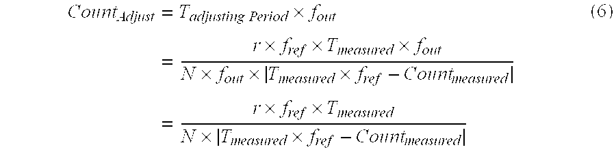
Recognizing that fin=N×fout, and substituting the right side of Eq. (1) for Counterror, we obtain: T Adjusting Period = r f in × f ref × T measured Count error = r N × f out × f ref × T measured T measured × f ref - Count measured = r × f ref × T measured N × f out × T measured × f ref - Count measured . ( 5 )
Figure US06304517-20011016-M00005
In embodiments such as the one shown in FIG. 5, the interval TAdjusting Period is determined by counting a corresponding number of cycles (herein denoted CountAdjust) of the clocking signal 570. In this case, CountAdjust is determined in accordance with: Count Adjust = T adjusting Period × f out = r × f ref × T measured × f out N × f out × T measured × f ref - Count measured = r × f ref × T measured N × T measured × f ref - Count measured ( 6 )
Figure US06304517-20011016-M00006
It will be observed that if N and M are selected so as to generate a clocking signal 570 having a nominal frequency of fout=1 Hz, and if the nominal measurement period Tmeasured, is selected to be 1 second, then Eq.(6) reduces to: Count Adjust = r × f ref N × f ref - Count measured . ( 7 )
Figure US06304517-20011016-M00007
As an illustrative example, consider an embodiment in which N=128, fref=13 MHZ, and Countmeasured=12,999,500. In this case, we find that the crystal oscillator 225 is fast (the reference clock stopped counting too soon), so the amount of adjustment will be r=1. Furthermore, these adjustments must be made once every TAdjusting Period=203.125 seconds (rounded to a value of 203). It is found that CountAdjust also has a rounded value of 203. This is not surprising, since the 1 Hz frequency of the clocking signal 570 means that there is a corresponding count for each second that we must wait.
In preferred embodiments, values for CountAdjust are represented by 15 bit values. A sign bit is also stored so that the appropriate adjustment (i.e., addition or subtraction) can be made to the division factor N.
Thus, at the conclusion of the calibration phase, values for r and CountAdjust are known. These values are applied during the normal operation of the RTC 220. Those elements of the RTC 220 that are pertinent to the initialization and correction phases of the correction routine will now be described with reference again being made to FIG. 5, and also to the flow chart of FIG. 6. The various steps described herein are carried out by a control unit 580, which may be embodied in any of a number of ways. For example, it may be a hard-wired logic controller. Alternatively, the control unit 580 may be a programmable processor executing a suitable set of program instructions. The invention may also be considered to be embodied in a computer readable storage medium having stored therein signals representative of the program instructions for carrying out the various steps described in this disclosure. Computer readable storage media include, but are not limited to magnetic storage media, such as magnetic disk or tape; and optical storage media, such as Compact Disk (CD) Read Only Memory (ROM) devices.
The initialization phase of the correction routine is performed whenever the phone is activated. As part of initialization (step 601), the operating system of the mobile telephone unit 210 copies the CountAdjust value from the memory 245 to a memory, which in the exemplary embodiment is a volatile memory such as a register 550, located in the RTC 220. This will ensure that the RTC 220 uses the correct value even if all power to the RTC 220 had been previously lost (i.e., in the event that a power back-up capacitor associated with the crystal oscillator 225 had been completely discharged).
In accordance with the present invention, a counter 510 is provided in the RTC 220 for counting the number of assertions of the clocking signal 570 that have occurred since the last correction. The value output by the counter 510 is compared, by a comparator 560, with the value stored in the register 550. When the counter 510 has reached the same value as the value stored in the register 550 (“YES” path out of decision block 603), an output signal from the comparator 560 is asserted, thereby causing the control unit 580 to adjust the value of N by an amount r (step 605). This is depicted schematically in FIG. 5 by the line connecting the output of the comparator 560 to an input of the second frequency divider 530. As explained earlier, adjusting the value of N in this manner causes the clocking signal 570 to be delayed or advanced by an amount r multiplied by the period of signal 590 being applied at the input of the second frequency divider 530. The purpose of this adjustment is to compensate for the inaccuracy of the 32 kHz crystal oscillator 225.
It is only desired to perform this correction once for every CountAdjust assertions of the clocking signal 570. Accordingly, the control unit 580 monitors the value in the counter 510 until it is further advanced to a value of CountAdjust+1 (decision block 607). When this occurs, the value of N is adjusted back to its original value (step 609), and the counter 510 is reset (step 611). The correction procedure is then repeated, beginning back at step 603. In this manner, the period between successive assertions of the clocking signal 570 will be increased or decreased by an amount equal to r/fin once for every CountAdjust non-adjusted assertions.
The accuracy of the adjusted RTC time counter is dependent on the accuracy of the high frequency clock (e.g., a 13 MHz clock). This technique disclosed herein reduces the fixed fault to less than 1 ppm (assuming that the accuracy of the high accuracy clock is better than 1 ppm) resulting in better accuracy of the RTC 220 in the mobile station at almost no cost. No extra equipment in the test environment is needed. Also, no extra time in production is needed. The calibration step can be performed simultaneously with other tests and there is no need for external control of the testing.
While the present invention has been described with respect to its preferred embodiments, those skilled in the art will recognize that the present invention is not limited to the specific embodiment described and illustrated herein. For example, although the exemplary embodiments utilize two frequency dividers 520 and 530, alternative embodiments could utilize fewer (i.e., one) or more frequency dividers for the purpose of converting the frequency of the crystal oscillator signal to the desired frequency of the clocking signal 570.
Accordingly, different embodiments and adaptations besides those shown herein and described as well as many variations, modifications and equivalent arrangements will now be apparent or will be reasonably suggested by the foregoing specification and drawings without departing from the substance of the scope of the invention.

Claims (39)

What is claimed is:
1. A method of generating a real time clock signal, comprising the steps of:
generating a high frequency clock signal;
generating a low frequency clock signal from the high frequency clock signal;
generating a corrected low frequency clock signal by adjusting a frequency of the low frequency clock signal by a predefined amount, r, once out of every CountAdjust assertions of the low frequency clock signal, wherein CountAdjust is an integer greater than one that is calculated as a function of r; and
supplying the corrected low frequency clock signal as the real time clock signal.
2. The method of claim 1, wherein the step of generating the corrected low frequency clock signal comprises the steps of:
counting assertions of the low frequency clock signal, thereby generating a present count value;
comparing the present count value with the CountAdjust; and
adjusting the frequency of the low frequency clock signal in response to the present count value being equal to the CountAdjust.
3. The method of claim 2, wherein:
the step of generating the low frequency clock signal from the high frequency clock signal comprises the step of using a frequency divider to generate one assertion of the low frequency clock signal for every N assertions of the high frequency clock signal, wherein N is an integer greater than one; and
the step of adjusting the frequency of the low frequency clock signal comprises the step of adjusting N by an amount r, wherein r is an integer having a magnitude greater than or equal to one.
4. The method of claim 3, further comprising the step of:
generating the high frequency clock signal from a higher frequency clock signal by using a second frequency divider to generate one assertion of the high frequency clock signal for every M assertions of the higher frequency clock signal, wherein M is an integer greater than one.
5. The method of claim 1, further comprising:
deriving the high frequency clock signal from a signal generated by a crystal oscillator.
6. The method of claim 1, further comprising the steps of:
generating CountAdjust by performing a calibration process that includes the steps of:
counting assertions of a first oscillator signal from which the high frequency clock signal is derived;
simultaneously counting assertions of a reference oscillator signal;
determining a measured count value representing a number of assertions of the reference oscillator signal that occurred for a predetermined number of assertions of the first oscillator signal;
generating an error count value by comparing the measured count value with an expected count value; and
converting the error count value to the CountAdjust.
7. The method of claim 6, wherein the step of converting the error count value to the CountAdjust comprises the step of computing: Count Adjust = r × f ref × T measured N × T measured × f ref - Count measured
Figure US06304517-20011016-M00008
wherein:
N is an integer that represents a ratio of frequencies of the high frequency clock signal and the low frequency clock signal;
Tmeasured is a nominal interval of time required for the first oscillator signal to be asserted the predetermined number of times;
r is an integer amount by which N will be adjusted once out of every CountAdjust assertions of the low frequency clock;
fref is a nominal frequency of the reference oscillator signal; and
Countmeasured is the measured count value.
8. The method of claim 1, wherein the low frequency clock signal is a 1 Hz signal.
9. The method of claim 1, further comprising the step of supplying the real time clock signal for use in a mobile terminal.
10. A method of determining an amount CountAdjust for use in an apparatus that generates a low frequency clock signal from a high frequency clock signal, and generates a corrected low frequency clock signal by adjusting a frequency of the low frequency clock signal once out of every CountAdjust assertions of the low frequency clock signal, wherein CountAdjust is an integer greater than one, the method comprising the steps of:
counting assertions of a first oscillator signal from which the high frequency clock signal is derived;
simultaneously counting assertions of a reference oscillator signal;
determining a measured count value representing a number of assertions of the reference oscillator signal that occurred for a predetermined number of assertions of the first oscillator signal;
generating an error count value by comparing the measured count value with an expected count value; and
converting the error count value to the CountAdjust.
11. The method of claim 10, wherein the step of converting the error count value to the CountAdjust comprises the step of computing: Count Adjust = r × f ref × T measured N × T measured × f ref - Count measured
Figure US06304517-20011016-M00009
wherein:
N is an integer that represents a ratio of frequencies of the high frequency clock signal and the low frequency clock signal;
Tmeasured is a nominal interval of time required for the first oscillator signal to be asserted the predetermined number of times;
r is an integer amount by which N will be adjusted once out of every CountAdjust assertions of the low frequency clock;
fref is a nominal frequency of the reference oscillator signal; and
Countmeasured is the measured count value.
12. The method of claim 10, further comprising the step of storing CountAdjust in a nonvolatile memory for use during operation of the apparatus.
13. A real time clock generator, comprising:
a frequency divider for generating a low frequency clock signal from a high frequency clock signal; and
means for generating a corrected low frequency clock signal by adjusting a frequency of the low frequency clock signal by a predefined amount, r, once out of every CountAdjust assertions of the low frequency clock signal, wherein CountAdjust is an integer greater than one that is calculated as a function of r.
14. The real time clock generator of claim 13, wherein the means for generating the corrected low frequency clock signal comprises:
a counter for counting assertions of the low frequency clock signal, thereby generating a present count value;
a comparator for comparing the present count value with the CountAdjust; and
an adjustment unit for adjusting the frequency of the low frequency clock signal in response to the present count value being equal to the CountAdjust.
15. The real time clock generator of claim 14, wherein:
the means for generating the low frequency clock signal from the high frequency clock signal comprises a frequency divider that generates one assertion of the low frequency clock signal for every N assertions of the high frequency clock signal, wherein N is an integer greater than one; and
the adjustment unit for adjusting the frequency of the low frequency clock signal comprises an adjustment unit that adjusts N by an amount r, wherein r is an integer having a magnitude greater than or equal to one.
16. The real time clock generator of claim 15, further comprising:
a second frequency divider that generate one assertion of the high frequency clock signal for every M assertions of a higher frequency clock signal, wherein M is an integer greater than one.
17. The real time clock generator of claim 13, further comprising:
a crystal oscillator for generating a crystal oscillator signal from which the high frequency clock signal is derived.
18. The real time clock generator of claim 13, further comprising:
calibration components for generating CountAdjust, comprising:
a first counter for counting assertions of a first oscillator signal from which the high frequency clock signal is derived;
a second counter for simultaneously counting assertions of a reference oscillator signal;
means for determining a measured count value representing a number of assertions of the reference oscillator signal that occurred for a predetermined number of assertions of the first oscillator signal;
a comparator for comparing the measured count value with an expected count value, thereby generating an error count value; and
means for converting the error count value to the CountAdjust.
19. The real time clock generator of claim 18, wherein the means for converting the error count value to the CountAdjust comprises means for computing: Count Adjust = r × f ref × T measured N × T measured × f ref - Count measured
Figure US06304517-20011016-M00010
wherein:
N is an integer that represents a ratio of frequencies of the high frequency clock signal and the low frequency clock signal;
Tmeasured is a nominal interval of time required for the first oscillator signal to be asserted the predetermined number of times;
r is an integer amount by which N will be adjusted once out of every CountAdjust assertions of the low frequency clock;
fref is a nominal frequency of the reference oscillator signal; and
Countmeasured is the measured count value.
20. The real time clock generator of claim 13, wherein the low frequency clock signal is a 1 Hz signal.
21. The real time clock generator of claim 13, further comprising means for supplying the real time clock signal to at least one component in a mobile terminal.
22. A calibration unit for determining an amount CountAdjust for use in an apparatus that generates a low frequency clock signal from a high frequency clock signal, and generates a corrected low frequency clock signal by adjusting a frequency of the low frequency clock signal once out of every CountAdjust assertions of the low frequency clock signal, wherein CountAdjust is an integer greater than one, the calibration unit comprising:
a first counter for counting assertions of a first oscillator signal from which the high frequency clock signal is derived;
a second counter for simultaneously counting assertions of a reference oscillator signal;
means for determining a measured count value representing a number of assertions of the reference oscillator signal that occurred for a predetermined number of assertions of the first oscillator signal;
a comparator for generating an error count value by comparing the measured count value with an expected count value; and
means for converting the error count value to the CountAdjust.
23. The calibration unit of claim 22, wherein the means for converting the error count value to the CountAdjust comprises means for computing: Count Adjust = r × f ref × T measured N × T measured × f ref - Count measured
Figure US06304517-20011016-M00011
wherein:
N is an integer that represents a ratio of frequencies of the high frequency clock signal and the low frequency clock signal;
Tmeasured is a nominal interval of time required for the first oscillator signal to be asserted the predetermined number of times;
r is an integer amount by which N will be adjusted once out of every CountAdjust assertions of the low frequency clock;
fref is a nominal frequency of the reference oscillator signal; and
Countmeasured is the measured count value.
24. The calibration unit of claim 22, further comprising a nonvolatile memory for storing CountAdjust for use during operation of the apparatus.
25. A mobile unit for use in a radiocommunication system, the mobile unit comprising:
a controller for controlling components in the mobile unit; and
a real time clock generator, comprising:
a frequency divider for generating a low frequency clock signal from a high frequency clock signal; and
means for generating a corrected low frequency clock signal by adjusting a frequency of the low frequency clock signal once out of every CountAdjust assertions of the low frequency clock signal, wherein CountAdjust is an integer greater than one.
26. The mobile unit of claim 25, wherein the means for generating the corrected low frequency clock signal comprises:
a counter for counting assertions of the low frequency clock signal, thereby generating a present count value;
a comparator for comparing the present count value with the CountAdjust; and
an adjustment unit for adjusting the frequency of the low frequency clock signal in response to the present count value being equal to the CountAdjust.
27. The mobile unit of claim 26, wherein:
the means for generating the low frequency clock signal from the high frequency clock signal comprises a frequency divider that generates one assertion of the low frequency clock signal for every N assertions of the high frequency clock signal, wherein N is an integer greater than one; and
the adjustment unit for adjusting the frequency of the low frequency clock signal comprises an adjustment unit that adjusts N by an amount r, wherein r is an integer having a magnitude greater than or equal to one.
28. The mobile unit of claim 27, wherein the real time clock generator further comprises:
a second frequency divider that generate one assertion of the high frequency clock signal for every M assertions of a higher frequency clock signal, wherein M is an integer greater than one.
29. The mobile unit of claim 25, further comprising:
a crystal oscillator for generating a crystal oscillator signal from which the high frequency clock signal is derived.
30. The mobile unit of claim 25, further comprising:
calibration components for generating CountAdjust, comprising:
a first counter for counting assertions of a first oscillator signal from which the high frequency clock signal is derived;
a second counter for simultaneously counting assertions of a reference oscillator signal;
means for determining a measured count value representing a number of assertions of the reference oscillator signal that occurred for a predetermined number of assertions of the first oscillator signal;
a comparator for comparing the measured count value with an expected count value, thereby generating an error count value; and
means for converting the error count value to the CountAdjust.
31. The mobile unit of claim 30, wherein the means for converting the error count value to the CountAdjust comprises means for computing: Count Adjust = r × f ref × T measured N × T measured × f ref - Count measured
Figure US06304517-20011016-M00012
wherein:
N is an integer that represents a ratio of frequencies of the high frequency clock signal and the low frequency clock signal;
Tmeasured is a nominal interval of time required for the first oscillator signal to be asserted the predetermined number of times;
r is an integer amount by which N will be adjusted once out of every CountAdjust assertions of the low frequency clock;
fref is a nominal frequency of the reference oscillator signal; and
Countmeasured is the measured count value.
32. The mobile unit of claim 25, wherein the low frequency clock signal is a 1 Hz signal.
33. The mobile unit of claim 25, further comprising a calibration unit for determining CountAdjust.
34. The mobile unit of claim 33, wherein the calibration unit comprises:
a first counter for counting assertions of a first oscillator signal from which the high frequency clock signal is derived;
a second counter for simultaneously counting assertions of a reference oscillator signal;
means for determining a measured count value representing a number of assertions of the reference oscillator signal that occurred for a predetermined number of assertions of the first oscillator signal;
a comparator for generating an error count value by comparing the measured count value with an expected count value; and
means for converting the error count value to the CountAdjust.
35. The mobile terminal of claim 34, further comprising:
a reference clock generator for generating the reference oscillator signal.
36. The mobile terminal of claim 35 wherein the reference clock generator is synchronized to a higher accuracy clock that is external to the mobile terminal.
37. The mobile terminal of claim 35, further comprising wireless means for coupling the reference clock generator and the higher accuracy clock.
38. The mobile terminal of claim 35, further comprising a wire connection for coupling the reference clock generator and the higher accuracy clock.
39. The mobile terminal of claim 34, wherein the reference oscillator signal is supplied by a reference clock generator that is located external to the mobile terminal.
US09/335,512 1999-06-18 1999-06-18 Method and apparatus for real time clock frequency error correction Expired - Lifetime US6304517B1 (en)

Priority Applications (7)

Application Number Priority Date Filing Date Title
US09/335,512 US6304517B1 (en) 1999-06-18 1999-06-18 Method and apparatus for real time clock frequency error correction
MYPI20002480 MY124738A (en) 1999-06-18 2000-06-02 Method and apparatus for real time clock frequency error correction.
AU54041/00A AU5404100A (en) 1999-06-18 2000-06-08 Method and apparatus for real time clock frequency error correction
JP2001505252A JP2003502980A (en) 1999-06-18 2000-06-08 Real-time clock frequency error correction method and apparatus
PCT/EP2000/005300 WO2000079349A2 (en) 1999-06-18 2000-06-08 Method and apparatus for real time clock frequency error correction
EP00938779A EP1196827A2 (en) 1999-06-18 2000-06-08 Method and apparatus for real time clock frequency error correction
CNB008114617A CN1149455C (en) 1999-06-18 2000-06-08 Method and apparatus for real time clock frequency error correction

Applications Claiming Priority (1)

Application Number Priority Date Filing Date Title
US09/335,512 US6304517B1 (en) 1999-06-18 1999-06-18 Method and apparatus for real time clock frequency error correction

Publications (1)

Publication Number Publication Date
US6304517B1 true US6304517B1 (en) 2001-10-16

Family

ID=23312102

Family Applications (1)

Application Number Title Priority Date Filing Date
US09/335,512 Expired - Lifetime US6304517B1 (en) 1999-06-18 1999-06-18 Method and apparatus for real time clock frequency error correction

Country Status (7)

Country Link
US (1) US6304517B1 (en)
EP (1) EP1196827A2 (en)
JP (1) JP2003502980A (en)
CN (1) CN1149455C (en)
AU (1) AU5404100A (en)
MY (1) MY124738A (en)
WO (1) WO2000079349A2 (en)

Cited By (54)

* Cited by examiner, † Cited by third party
Publication number Priority date Publication date Assignee Title
US20010020279A1 (en) * 1999-12-29 2001-09-06 Alanara Seppo Matias Clock
US6522100B2 (en) * 2000-10-16 2003-02-18 Sony International (Europe) Gmbh Battery management system
EP1304603A2 (en) 2001-10-19 2003-04-23 Lg Electronics Inc. Time error compensating apparatus and method in a terminal
US6556512B1 (en) * 1999-10-20 2003-04-29 Sony International (Europe) Gmbh Mobile terminal for a wireless telecommunication system with accurate real time generation
US20030112906A1 (en) * 2001-12-14 2003-06-19 John Pigott System for providing a calibrated clock and methods thereof
US6611922B2 (en) * 1999-08-09 2003-08-26 Power Measurement, Ltd. Power system time synchronization device and method for sequence of event recording
US6721372B1 (en) * 2000-03-17 2004-04-13 Lucent Technologies Inc. Intelligent software controlled correction of frequency tracking for a local oscillator of a receiver of a wireless device
US20040124934A1 (en) * 2002-12-30 2004-07-01 Chinnugounder Senthilkumar Duty cycle tuner for low power real time clock oscillator
US20040183665A1 (en) * 1999-02-05 2004-09-23 Schrader Bridgeport International, Inc. Method and apparatus for a remote tire pressure monitoring system
US6970701B1 (en) * 1999-11-02 2005-11-29 Skyworks Solutions, Inc. Radio calibration by correcting the crystal frequency
US20070116163A1 (en) * 2005-11-07 2007-05-24 Mamoru Nishimura Receiving circuit for multi-slot receiving provided with circuit for adjusting frequency characteristic of active filter
US7260732B1 (en) * 2004-07-28 2007-08-21 Microsoft Corporation Power regulation system and method for a portable electronic device
US7272078B1 (en) 2006-10-12 2007-09-18 Telefonaktiebolaget L M Ericsson (Publ) Efficient clock calibration in electronic equipment
US20070268787A1 (en) * 2006-05-19 2007-11-22 Mediatek Inc. Method and apparatus for a portable device
US20080222440A1 (en) * 2007-03-07 2008-09-11 Stephen Jones Real time clock calibration system
US20080316867A1 (en) * 2007-06-20 2008-12-25 Princeton Technology Corporation Correction apparatus and clock device using the same
US20090058539A1 (en) * 2007-09-03 2009-03-05 Hynix Semiconductor, Inc. Period signal generator of semiconductor integreated circuit
US20090129208A1 (en) * 2009-01-28 2009-05-21 Weiss Kenneth P Apparatus, system and method for keeping time
US20090160569A1 (en) * 2007-12-20 2009-06-25 Pentad Design Corporation Systems and methods for compensating for variations of the output of a real-time clock
US20090180358A1 (en) * 2008-01-10 2009-07-16 Oki Semiconductor Co., Ltd. Frequency corrector and clocking apparatus using the same
US20090296531A1 (en) * 2008-05-27 2009-12-03 Sony Ericsson Mobile Communications Ab Methods of Calibrating a Clock Using Multiple Clock Periods with a Single Counter and Related Devices and Methods
US20100058097A1 (en) * 2007-05-15 2010-03-04 Chronologic Pty. Ltd. Usb based synchronization and timing system
US20100090680A1 (en) * 2008-10-10 2010-04-15 Electro Industries/Gauge Tech. Intelligent electronic device having a terminal assembly for coupling to a meter mounting socket
US20100177564A1 (en) * 2009-01-14 2010-07-15 Micron Technology, Inc. Method for detecting flash program failures
WO2010093471A1 (en) * 2009-02-13 2010-08-19 Silego Technology, Inc. An integrated circuit frequency generator
US20100303185A1 (en) * 2009-06-02 2010-12-02 Jacobus Cornelis Haartsen Methods of Operating Wireless Communications Devices Including Detecting Times of Receipt of Packets and Related Devices
US20100301907A1 (en) * 2007-05-11 2010-12-02 Freescale Semiconductor, Inc. System and method for secure real time clocks
US20110204945A1 (en) * 2010-02-24 2011-08-25 Fujitsu Semiconductor Limited Calibration
US20120163134A1 (en) * 2009-12-23 2012-06-28 Sand9, Inc. Oscillators having arbitrary frequencies and related systems and methods
US20120250469A1 (en) * 2011-03-31 2012-10-04 Maxim Integrated Products, Inc. Apparatus and Method of Keeping Time of Day Over an Industrial Temperature Range
CN102721865A (en) * 2012-06-04 2012-10-10 惠州Tcl移动通信有限公司 Method and system for measuring accuracy of crystal oscillators
CN102830750A (en) * 2011-06-14 2012-12-19 赛酷特(北京)信息技术有限公司 Real-time clock with high precision
US20140009140A1 (en) * 2012-07-03 2014-01-09 Qiang Guo System for testing real time clock
US8767901B2 (en) * 2012-11-15 2014-07-01 Cortex Technology Corporation Real-time clock frequency correction devices
US8766646B2 (en) 2010-11-09 2014-07-01 Nuvoton Technology Corporation Calibration method and apparatus for clock signal and electronic device
CN104007652A (en) * 2014-06-16 2014-08-27 管存忠 Method for reducing electronic timing error
US20140247072A1 (en) * 2013-03-01 2014-09-04 Huawei Technologies Co., Ltd. Correction circuit and real-time clock circuit
US20140313065A1 (en) * 2013-03-15 2014-10-23 Analog Devices, Inc. Clock signal error correction in a digital-to-analog converter
TWI459181B (en) * 2009-12-31 2014-11-01 Giga Byte Tech Co Ltd Method and computer system for detecting rtc oscillator
US8917147B2 (en) * 2012-12-14 2014-12-23 Broadcom Corporation Method and system to improve power utilization using a calibrated crystal warm-up detection
US20150124918A1 (en) * 2013-11-04 2015-05-07 Si-En Technology Limited Method for compensating timing errors of real-time clocks
US9317059B2 (en) * 2013-11-20 2016-04-19 Intel IP Corporation Systems and methods for tracking elapsed time
CN105811933A (en) * 2014-12-31 2016-07-27 北京兆易创新科技股份有限公司 Calibrating method and system for improving 1Hz clock precision
US9897461B2 (en) 2015-02-27 2018-02-20 Electro Industries/Gauge Tech Intelligent electronic device with expandable functionality
CN107817871A (en) * 2016-09-10 2018-03-20 德州仪器德国股份有限公司 The frequency offset correction accuracy of real-time clock
CN105811930B (en) * 2014-12-31 2018-05-25 北京兆易创新科技股份有限公司 Improve the smooth method of adjustment of 1Hz clock accuracies and 1Hz clock systems
US20180149753A1 (en) * 2016-11-30 2018-05-31 Yujin Robot Co., Ltd. Ridar apparatus based on time of flight and moving object
US10048088B2 (en) 2015-02-27 2018-08-14 Electro Industries/Gauge Tech Wireless intelligent electronic device
US10056924B2 (en) 2013-08-19 2018-08-21 Analog Devices, Inc. High output power digital-to-analog converter system
USRE47601E1 (en) 2013-08-19 2019-09-10 Analog Devices, Inc. High output power digital-to-analog converter system
US10514401B2 (en) 2017-08-02 2019-12-24 Qualcomm Incorporated On-chip frequency monitoring
US11009922B2 (en) 2015-02-27 2021-05-18 Electro Industries/Gaugetech Wireless intelligent electronic device
CN114153135A (en) * 2021-12-22 2022-03-08 北京大学 Locking method of cesium beam atomic clock
US11429140B2 (en) * 2018-11-20 2022-08-30 Hyundai Mobis Co., Ltd. Real time clock device for vehicle and operating method thereof

Families Citing this family (9)

* Cited by examiner, † Cited by third party
Publication number Priority date Publication date Assignee Title
US6304517B1 (en) 1999-06-18 2001-10-16 Telefonaktiebolaget Lm Ericsson (Publ) Method and apparatus for real time clock frequency error correction
DE10112373A1 (en) * 2001-03-15 2002-09-26 Philips Corp Intellectual Pty Correcting real time clock for electronic unit involves determining time difference using error time per second within which real time clock is to be corrected by correction time difference
US7720467B2 (en) 2003-12-17 2010-05-18 Sharp Laboratories Of America, Inc. User notification for digital mobile phones
GB201100986D0 (en) * 2011-01-20 2011-03-09 Nordic Semiconductor Asa Low power oscillator
CN103023432A (en) * 2012-11-21 2013-04-03 无锡来燕微电子有限公司 Oscillation clock capable of automatically adjusting frequency and generated inside chip and designing method thereof
US9298874B2 (en) * 2014-02-07 2016-03-29 Qualcomm Incorporated Time-variant temperature-based 2-D and 3-D wire routing
CN109001970B (en) * 2017-06-07 2021-09-24 精工爱普生株式会社 Timepiece device, electronic apparatus, and moving object
EP3503629B1 (en) * 2017-12-21 2020-06-10 Stichting IMEC Nederland Transceiver device with real time clock
CN108521322B (en) * 2018-03-28 2020-02-07 西安电子科技大学 Method for adjusting local clock frequency of slave node based on minimum integral error of count value

Citations (34)

* Cited by examiner, † Cited by third party
Publication number Priority date Publication date Assignee Title
US4074514A (en) 1972-08-24 1978-02-21 Dynacore, S.A. Isochronous period generator having means for adjusting the isochronous period
US4110791A (en) * 1977-04-18 1978-08-29 The United States Of America As Represented By The Secretary Of The Navy Television projector system
GB2064248A (en) 1979-11-21 1981-06-10 Philcom Electronics Blackburn Temperature compensated crystal oscillators
US4282595A (en) 1979-12-21 1981-08-04 Timex Corporation Method for digital frequency trimming an oscillator in an electronic timepiece
US4325036A (en) * 1979-06-01 1982-04-13 Kabushiki Kaisha Daini Seikosha Temperature compensating circuit
EP0052884A1 (en) 1980-11-26 1982-06-02 Societe Suisse Pour L'industrie Horlogere Management Services S.A. Timepiece comprising a division ratio adjustable divider chain
US4448543A (en) * 1983-01-17 1984-05-15 Rockwell International Corporation Time-of-day clock having a temperature compensated low power frequency source
US4513259A (en) * 1982-12-23 1985-04-23 Rockwell International Corporation Closed loop temperature compensated frequency reference
US4646035A (en) 1984-01-13 1987-02-24 Thomson-Csf High precision tunable oscillator and radar equipped with same
US4903251A (en) 1989-09-05 1990-02-20 Ford Motor Company Accuracy adjustment for time-of-day clock using a microcontroller
US4949055A (en) 1986-08-30 1990-08-14 Franz Leitl Crystal oscillator compensation circuit
EP0511573A2 (en) 1991-04-19 1992-11-04 Seikosha Co., Ltd. Clock with clock adjusting data memory
US5204975A (en) 1989-10-12 1993-04-20 Seiko Epson Corporation Digitally-corrected temperature-compensated crystal oscillator having a correction-suspend control for communications service
EP0568256A1 (en) 1992-05-01 1993-11-03 Hewlett-Packard Company Airflow system for thermal ink-jet printer
US5305453A (en) 1990-08-30 1994-04-19 Bull S.A. Process and device for adjusting clock signals in a synchronous system
US5327404A (en) * 1990-11-27 1994-07-05 Vlsi Technology, Inc. On-chip frequency trimming method for real-time clock
JPH0746039A (en) 1993-07-27 1995-02-14 Seiko Epson Corp Temperature compensated crystal oscillator
WO1995011456A1 (en) 1993-10-22 1995-04-27 Toyo Communication Equipment Co., Ltd. Frequency counter and frequency counting method
EP0683443A2 (en) 1994-05-20 1995-11-22 Nec Corporation Time correction of an electronic clock
US5473284A (en) 1992-04-02 1995-12-05 Nokia Telecommunications Oy Oscillator frequency control loop based on long term average of frequency difference
US5481507A (en) 1993-11-29 1996-01-02 Mitsubishi Denki Kabushiki Kaisha Electronic timekeeping device reduced adjustment data storage requirement
JPH0870218A (en) 1994-08-29 1996-03-12 Murata Mfg Co Ltd Temperature compensated crystal oscillator
US5546363A (en) * 1994-03-03 1996-08-13 Fujitsu Limited Clock apparatus for forming time information for use in computer system
JPH08237030A (en) 1995-02-28 1996-09-13 Nec Corp Temperature compensation device for crystal oscillation circuit
JPH08265044A (en) 1995-03-23 1996-10-11 Tokai Rika Co Ltd Transmitter
WO1996037959A1 (en) 1995-05-26 1996-11-28 Robert Bosch Gmbh Telecommunication terminal
WO1997004366A1 (en) 1995-07-21 1997-02-06 Honeywell Inc. A method for calibrating a real-time clock
EP0768583A2 (en) 1995-10-16 1997-04-16 Nec Corporation A method and apparatus for generating a clock signal which is compensated for a clock rate deviation therefor
US5717661A (en) 1994-12-20 1998-02-10 Poulson; T. Earl Method and apparatus for adjusting the accuracy of electronic timepieces
US5719827A (en) * 1994-11-04 1998-02-17 Aulab S.A. Highly stable frequency generator
US5767747A (en) * 1995-08-18 1998-06-16 International Business Machines Corporation Electronic low power clock circuit and method
EP0851593A2 (en) 1996-12-27 1998-07-01 Matsushita Electric Industrial Co., Ltd. Receiving portion of radio communication device
US5831485A (en) * 1997-09-04 1998-11-03 Tektronix, Inc. Method and apparatus for producing a temperature stable frequency using two oscillators
WO2000079349A2 (en) 1999-06-18 2000-12-28 Telefonaktiebolaget Lm Ericsson (Publ) Method and apparatus for real time clock frequency error correction

Family Cites Families (1)

* Cited by examiner, † Cited by third party
Publication number Priority date Publication date Assignee Title
FI95980C (en) * 1992-09-04 1996-04-10 Nokia Mobile Phones Ltd Method and switchgear for accurate measurement of time with an inaccurate clock

Patent Citations (36)

* Cited by examiner, † Cited by third party
Publication number Priority date Publication date Assignee Title
US4074514A (en) 1972-08-24 1978-02-21 Dynacore, S.A. Isochronous period generator having means for adjusting the isochronous period
US4110791A (en) * 1977-04-18 1978-08-29 The United States Of America As Represented By The Secretary Of The Navy Television projector system
US4325036A (en) * 1979-06-01 1982-04-13 Kabushiki Kaisha Daini Seikosha Temperature compensating circuit
GB2064248A (en) 1979-11-21 1981-06-10 Philcom Electronics Blackburn Temperature compensated crystal oscillators
US4282595A (en) 1979-12-21 1981-08-04 Timex Corporation Method for digital frequency trimming an oscillator in an electronic timepiece
US4456386A (en) * 1980-11-26 1984-06-26 Societe Suisse Pour L'industrie Horlogere Management Services S.A. Timepiece having a divider chain with an adjustable division rate
EP0052884A1 (en) 1980-11-26 1982-06-02 Societe Suisse Pour L'industrie Horlogere Management Services S.A. Timepiece comprising a division ratio adjustable divider chain
US4513259A (en) * 1982-12-23 1985-04-23 Rockwell International Corporation Closed loop temperature compensated frequency reference
US4448543A (en) * 1983-01-17 1984-05-15 Rockwell International Corporation Time-of-day clock having a temperature compensated low power frequency source
US4646035A (en) 1984-01-13 1987-02-24 Thomson-Csf High precision tunable oscillator and radar equipped with same
US4949055A (en) 1986-08-30 1990-08-14 Franz Leitl Crystal oscillator compensation circuit
US4903251A (en) 1989-09-05 1990-02-20 Ford Motor Company Accuracy adjustment for time-of-day clock using a microcontroller
US5204975A (en) 1989-10-12 1993-04-20 Seiko Epson Corporation Digitally-corrected temperature-compensated crystal oscillator having a correction-suspend control for communications service
US5305453A (en) 1990-08-30 1994-04-19 Bull S.A. Process and device for adjusting clock signals in a synchronous system
US5327404A (en) * 1990-11-27 1994-07-05 Vlsi Technology, Inc. On-chip frequency trimming method for real-time clock
EP0511573A2 (en) 1991-04-19 1992-11-04 Seikosha Co., Ltd. Clock with clock adjusting data memory
US5473284A (en) 1992-04-02 1995-12-05 Nokia Telecommunications Oy Oscillator frequency control loop based on long term average of frequency difference
EP0568256A1 (en) 1992-05-01 1993-11-03 Hewlett-Packard Company Airflow system for thermal ink-jet printer
JPH0746039A (en) 1993-07-27 1995-02-14 Seiko Epson Corp Temperature compensated crystal oscillator
WO1995011456A1 (en) 1993-10-22 1995-04-27 Toyo Communication Equipment Co., Ltd. Frequency counter and frequency counting method
US5481507A (en) 1993-11-29 1996-01-02 Mitsubishi Denki Kabushiki Kaisha Electronic timekeeping device reduced adjustment data storage requirement
US5546363A (en) * 1994-03-03 1996-08-13 Fujitsu Limited Clock apparatus for forming time information for use in computer system
US5748570A (en) * 1994-05-20 1998-05-05 Nec Corporation Time correction of an electronic clock
EP0683443A2 (en) 1994-05-20 1995-11-22 Nec Corporation Time correction of an electronic clock
JPH0870218A (en) 1994-08-29 1996-03-12 Murata Mfg Co Ltd Temperature compensated crystal oscillator
US5719827A (en) * 1994-11-04 1998-02-17 Aulab S.A. Highly stable frequency generator
US5717661A (en) 1994-12-20 1998-02-10 Poulson; T. Earl Method and apparatus for adjusting the accuracy of electronic timepieces
JPH08237030A (en) 1995-02-28 1996-09-13 Nec Corp Temperature compensation device for crystal oscillation circuit
JPH08265044A (en) 1995-03-23 1996-10-11 Tokai Rika Co Ltd Transmitter
WO1996037959A1 (en) 1995-05-26 1996-11-28 Robert Bosch Gmbh Telecommunication terminal
WO1997004366A1 (en) 1995-07-21 1997-02-06 Honeywell Inc. A method for calibrating a real-time clock
US5767747A (en) * 1995-08-18 1998-06-16 International Business Machines Corporation Electronic low power clock circuit and method
EP0768583A2 (en) 1995-10-16 1997-04-16 Nec Corporation A method and apparatus for generating a clock signal which is compensated for a clock rate deviation therefor
EP0851593A2 (en) 1996-12-27 1998-07-01 Matsushita Electric Industrial Co., Ltd. Receiving portion of radio communication device
US5831485A (en) * 1997-09-04 1998-11-03 Tektronix, Inc. Method and apparatus for producing a temperature stable frequency using two oscillators
WO2000079349A2 (en) 1999-06-18 2000-12-28 Telefonaktiebolaget Lm Ericsson (Publ) Method and apparatus for real time clock frequency error correction

Cited By (87)

* Cited by examiner, † Cited by third party
Publication number Priority date Publication date Assignee Title
US20040183665A1 (en) * 1999-02-05 2004-09-23 Schrader Bridgeport International, Inc. Method and apparatus for a remote tire pressure monitoring system
US6611922B2 (en) * 1999-08-09 2003-08-26 Power Measurement, Ltd. Power system time synchronization device and method for sequence of event recording
US6556512B1 (en) * 1999-10-20 2003-04-29 Sony International (Europe) Gmbh Mobile terminal for a wireless telecommunication system with accurate real time generation
US6970701B1 (en) * 1999-11-02 2005-11-29 Skyworks Solutions, Inc. Radio calibration by correcting the crystal frequency
US20010020279A1 (en) * 1999-12-29 2001-09-06 Alanara Seppo Matias Clock
US6721372B1 (en) * 2000-03-17 2004-04-13 Lucent Technologies Inc. Intelligent software controlled correction of frequency tracking for a local oscillator of a receiver of a wireless device
US6522100B2 (en) * 2000-10-16 2003-02-18 Sony International (Europe) Gmbh Battery management system
EP1304603A2 (en) 2001-10-19 2003-04-23 Lg Electronics Inc. Time error compensating apparatus and method in a terminal
EP1304603A3 (en) * 2001-10-19 2006-08-16 Lg Electronics Inc. Time error compensating apparatus and method in a terminal
US20030112906A1 (en) * 2001-12-14 2003-06-19 John Pigott System for providing a calibrated clock and methods thereof
US7058149B2 (en) 2001-12-14 2006-06-06 Freescale Semiconductor, Inc. System for providing a calibrated clock and methods thereof
US6791428B2 (en) * 2002-12-30 2004-09-14 Intel Corporation Duty cycle tuner for low power real time clock oscillator
US20040124934A1 (en) * 2002-12-30 2004-07-01 Chinnugounder Senthilkumar Duty cycle tuner for low power real time clock oscillator
US7260732B1 (en) * 2004-07-28 2007-08-21 Microsoft Corporation Power regulation system and method for a portable electronic device
US20070116163A1 (en) * 2005-11-07 2007-05-24 Mamoru Nishimura Receiving circuit for multi-slot receiving provided with circuit for adjusting frequency characteristic of active filter
US7894558B2 (en) * 2005-11-07 2011-02-22 Panasonic Corporation Receiving circuit for multi-slot receiving provided with circuit for adjusting frequency characteristic of active filter
US7455447B2 (en) 2006-05-19 2008-11-25 Mediatek Inc. Method and apparatus for a portable device
US20070268787A1 (en) * 2006-05-19 2007-11-22 Mediatek Inc. Method and apparatus for a portable device
US7272078B1 (en) 2006-10-12 2007-09-18 Telefonaktiebolaget L M Ericsson (Publ) Efficient clock calibration in electronic equipment
US20080222440A1 (en) * 2007-03-07 2008-09-11 Stephen Jones Real time clock calibration system
US20100301907A1 (en) * 2007-05-11 2010-12-02 Freescale Semiconductor, Inc. System and method for secure real time clocks
US8341443B2 (en) * 2007-05-11 2012-12-25 Freescale Semiconductor, Inc. System and method for secure real time clocks
US20100058097A1 (en) * 2007-05-15 2010-03-04 Chronologic Pty. Ltd. Usb based synchronization and timing system
US20080316867A1 (en) * 2007-06-20 2008-12-25 Princeton Technology Corporation Correction apparatus and clock device using the same
US7854544B2 (en) * 2007-06-20 2010-12-21 Princeton Technology Corporation Correction apparatus and clock device using the same
US7705688B2 (en) * 2007-09-03 2010-04-27 Hynix Semiconductor Inc. Period signal generator of semiconductor integrated circuit
US20090058539A1 (en) * 2007-09-03 2009-03-05 Hynix Semiconductor, Inc. Period signal generator of semiconductor integreated circuit
US20090160569A1 (en) * 2007-12-20 2009-06-25 Pentad Design Corporation Systems and methods for compensating for variations of the output of a real-time clock
US7791418B2 (en) 2007-12-20 2010-09-07 Pentad Design, Llc Systems and methods for compensating for variations of the output of a real-time clock
US8201991B2 (en) * 2008-01-10 2012-06-19 Oki Semiconductor Co., Ltd. Frequency corrector and clocking apparatus using the same
US20090180358A1 (en) * 2008-01-10 2009-07-16 Oki Semiconductor Co., Ltd. Frequency corrector and clocking apparatus using the same
US20090296531A1 (en) * 2008-05-27 2009-12-03 Sony Ericsson Mobile Communications Ab Methods of Calibrating a Clock Using Multiple Clock Periods with a Single Counter and Related Devices and Methods
US8219345B2 (en) 2008-05-27 2012-07-10 Sony Ericsson Mobile Communications Ab Methods of calibrating a clock using multiple clock periods with a single counter and related devices and methods
US7881895B2 (en) 2008-05-27 2011-02-01 Sony Ericsson Mobile Communications Ab Methods of calibrating a clock using multiple clock periods with a single counter and related devices and methods
US20110087449A1 (en) * 2008-05-27 2011-04-14 Jacobus Cornelis Haartsen Methods of Calibrating a Clock Using Multiple Clock Periods with a Single Counter and Related Devices and Methods
US20100090680A1 (en) * 2008-10-10 2010-04-15 Electro Industries/Gauge Tech. Intelligent electronic device having a terminal assembly for coupling to a meter mounting socket
US8717007B2 (en) 2008-10-10 2014-05-06 Electro Industries/Gauge Tech Intelligent electronic device having a terminal assembly for coupling to a meter mounting socket
US8250417B2 (en) * 2009-01-14 2012-08-21 Micron Technology, Inc. Method for detecting flash program failures
US20100177564A1 (en) * 2009-01-14 2010-07-15 Micron Technology, Inc. Method for detecting flash program failures
US8468400B2 (en) 2009-01-14 2013-06-18 Micron Technology, Inc. Method for detecting flash program failures
US20090129208A1 (en) * 2009-01-28 2009-05-21 Weiss Kenneth P Apparatus, system and method for keeping time
US8368478B2 (en) 2009-02-13 2013-02-05 Silego Technology, Inc. Integrated circuit frequency generator
WO2010093471A1 (en) * 2009-02-13 2010-08-19 Silego Technology, Inc. An integrated circuit frequency generator
US20100214030A1 (en) * 2009-02-13 2010-08-26 Silego Technology, Inc. Integrated circuit frequency generator
US20100303185A1 (en) * 2009-06-02 2010-12-02 Jacobus Cornelis Haartsen Methods of Operating Wireless Communications Devices Including Detecting Times of Receipt of Packets and Related Devices
US8896385B2 (en) * 2009-12-23 2014-11-25 Sand 9, Inc. Oscillators having arbitrary frequencies and related systems and methods
US20120163134A1 (en) * 2009-12-23 2012-06-28 Sand9, Inc. Oscillators having arbitrary frequencies and related systems and methods
TWI459181B (en) * 2009-12-31 2014-11-01 Giga Byte Tech Co Ltd Method and computer system for detecting rtc oscillator
US20110204945A1 (en) * 2010-02-24 2011-08-25 Fujitsu Semiconductor Limited Calibration
US8713346B2 (en) 2010-02-24 2014-04-29 Fujitsu Semiconductor Limited Resuming piecewise calibration of a real-time-clock unit after a measured offset that begins at the next calibration period
EP2369438A1 (en) 2010-02-24 2011-09-28 Fujitsu Semiconductor Limited Calibration method of a real time clock signal
US8766646B2 (en) 2010-11-09 2014-07-01 Nuvoton Technology Corporation Calibration method and apparatus for clock signal and electronic device
US20120250469A1 (en) * 2011-03-31 2012-10-04 Maxim Integrated Products, Inc. Apparatus and Method of Keeping Time of Day Over an Industrial Temperature Range
US9342054B2 (en) * 2011-03-31 2016-05-17 Maxim Integrated Products, Inc. Apparatus and method of keeping time of day over an industrial temperature range
CN102830750A (en) * 2011-06-14 2012-12-19 赛酷特(北京)信息技术有限公司 Real-time clock with high precision
CN102721865A (en) * 2012-06-04 2012-10-10 惠州Tcl移动通信有限公司 Method and system for measuring accuracy of crystal oscillators
US20140009140A1 (en) * 2012-07-03 2014-01-09 Qiang Guo System for testing real time clock
US8767901B2 (en) * 2012-11-15 2014-07-01 Cortex Technology Corporation Real-time clock frequency correction devices
US8917147B2 (en) * 2012-12-14 2014-12-23 Broadcom Corporation Method and system to improve power utilization using a calibrated crystal warm-up detection
US9362920B2 (en) * 2013-03-01 2016-06-07 Huawei Technologies Co., Ltd. Correction circuit and real-time clock circuit
US20140247072A1 (en) * 2013-03-01 2014-09-04 Huawei Technologies Co., Ltd. Correction circuit and real-time clock circuit
US9154148B2 (en) * 2013-03-15 2015-10-06 Analog Devices, Inc. Clock signal error correction in a digital-to-analog converter
US20140313065A1 (en) * 2013-03-15 2014-10-23 Analog Devices, Inc. Clock signal error correction in a digital-to-analog converter
USRE47601E1 (en) 2013-08-19 2019-09-10 Analog Devices, Inc. High output power digital-to-analog converter system
US10056924B2 (en) 2013-08-19 2018-08-21 Analog Devices, Inc. High output power digital-to-analog converter system
US9304498B2 (en) * 2013-11-04 2016-04-05 Si-En Technology Limited Method for compensating timing errors of real-time clocks
US20150124918A1 (en) * 2013-11-04 2015-05-07 Si-En Technology Limited Method for compensating timing errors of real-time clocks
US9317059B2 (en) * 2013-11-20 2016-04-19 Intel IP Corporation Systems and methods for tracking elapsed time
CN104007652A (en) * 2014-06-16 2014-08-27 管存忠 Method for reducing electronic timing error
CN105811933B (en) * 2014-12-31 2018-06-29 北京兆易创新科技股份有限公司 A kind of calibration method and system for improving 1Hz clock accuracies
CN105811933A (en) * 2014-12-31 2016-07-27 北京兆易创新科技股份有限公司 Calibrating method and system for improving 1Hz clock precision
CN105811930B (en) * 2014-12-31 2018-05-25 北京兆易创新科技股份有限公司 Improve the smooth method of adjustment of 1Hz clock accuracies and 1Hz clock systems
US9897461B2 (en) 2015-02-27 2018-02-20 Electro Industries/Gauge Tech Intelligent electronic device with expandable functionality
US11641052B2 (en) 2015-02-27 2023-05-02 El Electronics Llc Wireless intelligent electronic device
US10274340B2 (en) 2015-02-27 2019-04-30 Electro Industries/Gauge Tech Intelligent electronic device with expandable functionality
US11644341B2 (en) 2015-02-27 2023-05-09 El Electronics Llc Intelligent electronic device with hot swappable battery
US10739162B2 (en) 2015-02-27 2020-08-11 Electro Industries/Gauge Tech Intelligent electronic device with surge supression
US10048088B2 (en) 2015-02-27 2018-08-14 Electro Industries/Gauge Tech Wireless intelligent electronic device
US11009922B2 (en) 2015-02-27 2021-05-18 Electro Industries/Gaugetech Wireless intelligent electronic device
CN107817871B (en) * 2016-09-10 2023-06-06 德州仪器公司 Frequency offset correction accuracy for real-time clocks
CN107817871A (en) * 2016-09-10 2018-03-20 德州仪器德国股份有限公司 The frequency offset correction accuracy of real-time clock
US10962647B2 (en) * 2016-11-30 2021-03-30 Yujin Robot Co., Ltd. Lidar apparatus based on time of flight and moving object
US20180149753A1 (en) * 2016-11-30 2018-05-31 Yujin Robot Co., Ltd. Ridar apparatus based on time of flight and moving object
US10514401B2 (en) 2017-08-02 2019-12-24 Qualcomm Incorporated On-chip frequency monitoring
US11429140B2 (en) * 2018-11-20 2022-08-30 Hyundai Mobis Co., Ltd. Real time clock device for vehicle and operating method thereof
CN114153135B (en) * 2021-12-22 2022-08-09 北京大学 Locking method of cesium beam atomic clock
CN114153135A (en) * 2021-12-22 2022-03-08 北京大学 Locking method of cesium beam atomic clock

Also Published As

Publication number Publication date
AU5404100A (en) 2001-01-09
WO2000079349A3 (en) 2001-05-25
CN1369067A (en) 2002-09-11
MY124738A (en) 2006-07-31
EP1196827A2 (en) 2002-04-17
JP2003502980A (en) 2003-01-21
CN1149455C (en) 2004-05-12
WO2000079349A2 (en) 2000-12-28

Similar Documents

Publication Publication Date Title
US6304517B1 (en) Method and apparatus for real time clock frequency error correction
JP4164662B2 (en) Portable terminal and GPS time keeping method
TWI399548B (en) Efficient clock calibration in electronic equipment
US7403507B2 (en) System and method for recovering system time in direct sequence spread spectrum communications
JPH08251656A (en) Radiotelephone
EP1133825B1 (en) Methods and systems for frequency generation for wireless devices
JP2001159690A (en) Portable device and real time information production method
US20040152438A1 (en) Timing control device and timing control method
US20060045215A1 (en) Method and apparatus for frequency correcting a periodic signal
CN107135179B (en) Equipment frequency calibration method and equipment
EP1395072B1 (en) Radio communication apparatus and its reception timing estimating method
US8719614B2 (en) Apparatus and method for generating a timing signal
US7149555B2 (en) Mobile phone capable of stopping main clock signal
US9294999B2 (en) Technique for maintaining a radio time base
CN110876178B (en) 32K clock calibration method and device
US6970701B1 (en) Radio calibration by correcting the crystal frequency
US11864143B2 (en) Method for adjusting target clock and wireless device thereof
TWI533595B (en) Communication device and control method thereof
JPH10257004A (en) Communication equipment
JP2008124524A (en) Intermittent reception control apparatus
JPH1093432A (en) Frequency synthesizer
JP2002152036A (en) Reference signal generator
KR20050035587A (en) Frequency calibration apparatus of low power osicllator of bluetooth and method the same
JPH11113053A (en) Clock time correction method for mobile station and circuit for the same

Legal Events

Date Code Title Description
AS Assignment

Owner name: TELEFONAKTIEBOLAGE LM ERICSSON, SWEDEN

Free format text: ASSIGNMENT OF ASSIGNORS INTEREST;ASSIGNORS:LEDFELT, ROLF ERIK;OSTSJO, ANDERS WILHELM;REEL/FRAME:010062/0010

Effective date: 19990617

AS Assignment

Owner name: TELEFONAKTIEBOLAGET LM ERICSSON, SWEDEN

Free format text: CORRECTIVE ASSIGNMENT TO CORRECT THE NAME OF THE ASSIGNEE AN ASSIGNMENT WAS PREVIOUSLY RECORDED ON REEL 010062 FRAME 0010;ASSIGNORS:LEDFELT, ROLF ERIK;OSTSJO, ANDERS WILHELM;REEL/FRAME:010358/0240

Effective date: 19990617

STCF Information on status: patent grant

Free format text: PATENTED CASE

FPAY Fee payment

Year of fee payment: 4

REMI Maintenance fee reminder mailed
FPAY Fee payment

Year of fee payment: 8

SULP Surcharge for late payment

Year of fee payment: 7

FPAY Fee payment

Year of fee payment: 12