US6397156B1 - Impedance measurement system for power system transmission lines - Google Patents

Impedance measurement system for power system transmission lines Download PDF

Info

Publication number
US6397156B1
US6397156B1 US09/192,851 US19285198A US6397156B1 US 6397156 B1 US6397156 B1 US 6397156B1 US 19285198 A US19285198 A US 19285198A US 6397156 B1 US6397156 B1 US 6397156B1
Authority
US
United States
Prior art keywords
power system
values
current
voltage
processor
Prior art date
Legal status (The legal status is an assumption and is not a legal conclusion. Google has not performed a legal analysis and makes no representation as to the accuracy of the status listed.)
Expired - Fee Related
Application number
US09/192,851
Inventor
Bernhard Bachmann
David G. Hart
Yi Hu
Damir Novosel
Murari M. Saha
Current Assignee (The listed assignees may be inaccurate. Google has not performed a legal analysis and makes no representation or warranty as to the accuracy of the list.)
ABB Inc USA
Original Assignee
ABB Inc USA
Priority date (The priority date is an assumption and is not a legal conclusion. Google has not performed a legal analysis and makes no representation as to the accuracy of the date listed.)
Filing date
Publication date
Application filed by ABB Inc USA filed Critical ABB Inc USA
Priority to US09/192,851 priority Critical patent/US6397156B1/en
Assigned to ABB POWER T&D COMPANY INC. reassignment ABB POWER T&D COMPANY INC. ASSIGNMENT OF ASSIGNORS INTEREST (SEE DOCUMENT FOR DETAILS). Assignors: BACHMANN, BERNHARD, HART, DAVID G., HU, YI, NOVOSEL, DAMIR
Priority to AU12377/00A priority patent/AU1237700A/en
Priority to PCT/US1999/025229 priority patent/WO2000030233A1/en
Priority to EP99972381A priority patent/EP1142076A4/en
Assigned to ABB POWER T&D COMPANY INC. reassignment ABB POWER T&D COMPANY INC. ASSIGNMENT OF ASSIGNORS INTEREST (SEE DOCUMENT FOR DETAILS). Assignors: SAHA, MURARI M., BACHMANN, BERNHARD, HART, DAVID G., HU, YI, NOVOSEL, DAMIR
Application granted granted Critical
Publication of US6397156B1 publication Critical patent/US6397156B1/en
Anticipated expiration legal-status Critical
Expired - Fee Related legal-status Critical Current

Links

Images

Classifications

    • HELECTRICITY
    • H02GENERATION; CONVERSION OR DISTRIBUTION OF ELECTRIC POWER
    • H02HEMERGENCY PROTECTIVE CIRCUIT ARRANGEMENTS
    • H02H3/00Emergency protective circuit arrangements for automatic disconnection directly responsive to an undesired change from normal electric working condition with or without subsequent reconnection ; integrated protection
    • H02H3/40Emergency protective circuit arrangements for automatic disconnection directly responsive to an undesired change from normal electric working condition with or without subsequent reconnection ; integrated protection responsive to ratio of voltage and current
    • HELECTRICITY
    • H02GENERATION; CONVERSION OR DISTRIBUTION OF ELECTRIC POWER
    • H02HEMERGENCY PROTECTIVE CIRCUIT ARRANGEMENTS
    • H02H1/00Details of emergency protective circuit arrangements
    • H02H1/04Arrangements for preventing response to transient abnormal conditions, e.g. to lightning or to short duration over voltage or oscillations; Damping the influence of dc component by short circuits in ac networks

Definitions

  • the present invention relates generally to protective relaying, and more particularly to a method and apparatus for use in connection with a protective relay or like device to accurately measure the impedance of a power system transmission line.
  • a typical power system employs one or more protective relays to monitor impedance and other AC voltage and current characteristics on a protected transmission line, to sense faults and short circuits on such protected line, and to appropriately isolate such faults and short circuits from the remainder of the power system by tripping pre-positioned circuit breakers on such protected line.
  • a typical power system can be connected over hundreds of miles and include multiple power generators (generator S, generator R) at different locations.
  • Transmission lines (the main horizontal lines in Fig. 1) distribute power from the generators to secondary lines or buses (the main vertical lines in Fig. 1 ), and such buses eventually lead to power loads.
  • relays and circuit breakers are appropriately positioned to perform the isolating function described above.
  • a modern protective relay typically records voltage and current waveforms measured on a corresponding protected line, and employs a memory and microprocessor and/or digital signal processor (DSP) to process the recorded waveforms and to estimate impedance and voltage and current phasors based on such processed waveforms.
  • DSP digital signal processor
  • a voltage or current phasor expresses the respective parameter in terms of its magnitude and phase angle.
  • transmission line includes any type of electrical conductor, such as a high power conductor, feeder, transformer winding, etc. Based on the estimated impedance and voltage and current phasors, the protective relay can then decide whether to trip an associated relay, thereby isolating a portion of the power system.
  • a typical protective relay 10 samples voltage and current waveforms V A , V B , V C , I A , I B , I C from each phase (A-C) of a three phase line 12 .
  • the sampled waveforms are stored in a memory 14 and are then retrieved and appropriately operated on by a processor or DSP 16 to produce the aforementioned estimated impedances and phasors.
  • the relay 10 may then decide that an associated circuit breaker 18 should be tripped to isolate a portion of the line 12 from a fault condition or from other detected phenomena, and issue such a command over a ‘TRIP’ output (‘TRIP 1 ’ in Fig. 1A) that is received as an input to the circuit breaker 18 .
  • the relay 10 may then reset the circuit breaker after the relay 10 senses that the fault has been cleared, or after otherwise being ordered to do so, by issuing such a command over a ‘RESET’ output (‘RESET’ 1 in FIG. 1A) that is received as an input to the circuit breaker 18 .
  • the relay 10 may control several circuit breakers 18 (only one being shown in FIG. 1 A), hence the ‘TRIP 2 ’ and ‘RESET 2 ’ outputs.
  • the circuit breakers 18 may be set up to control one or more specific phases of the line 12 , rather than all of the phases of the line 12 . Owing to the relatively large distances over which a power system can extend, the distance between a relay 10 and one or more of its associated circuit breakers 18 can be substantial. As a result, the outputs from the relay 10 may be received by the circuit breaker(s) 18 by way of any reasonable transmission method, including hard wire line, radio transmission, optical link, satellite link, and the like.
  • transmission lines may oftentimes be series-compensated by series capacitance 20 that includes one or more capacitors or banks of capacitor installations (a representative series capacitor CAP is shown).
  • Benefits obtained thereby include increased power transfer capability, improved system stability, reduced system losses, improved voltage regulation, and better power flow regulation.
  • installation of series capacitance introduces challenges to protection systems for both the series-compensated line and lines adjacent thereto.
  • series compensation elements installed within a power system introduce harmonics and non-linearities in such system.
  • waveform-type algorithms i.e., algorithms that rely on current and voltage waveforms to determine a parameter of interest
  • several transient problems may cause very large errors.
  • DC Offset In uncompensated and compensated power systems, a fault current waveform will contain an exponentially decaying DC offset component in addition to a fundamental frequency. The amount of the DC offset is dependent on the fault inception angle and system parameters such as network configuration, number and length of transmission lines, compensation percentage, power flow, generator and transformer impedances, etc.
  • a variety of algorithms have been devised to compensate for DC offset. Some algorithms use a differentiation technique that eliminates the effect of the DC offset and ramp components in the fault current waveform. Mimic circuits and cosine filters have also been employed.
  • Sub-Synchronous Frequencies On series-compensated lines, series capacitance introduces a sub-synchronous frequency which is dependent on capacitance value and various system values.
  • the fault current waveform includes two sinusoids, one oscillating at the predetermined system frequency (50 Hz, 60 Hz, etc.), and the other at the system natural frequency (neglecting system resistance and load current).
  • the system natural frequency is determined by the degree of compensation, the source impedance, and the distance to fault location, among other things. Accordingly, a higher system natural frequency occurs when a fault is closer to a respective relay. The higher frequency will not be as critical for close-in faults since a metal oxide varistor (MOV) associated with the series capacitance (shown in FIG.
  • MOV metal oxide varistor
  • a bypass breaker or bypass switch (shown in FIG. 2 in parallel with the representative series capacitor) closes following operation of an overload protection system.
  • the breaker is controlled by a protective relay 10 via an appropriate BYPASS output (FIG. 1 A).
  • BYPASS output FIG. 1 A
  • bypassing the installed capacitance in actuality causes an inductance (L) to be placed in parallel with the installed capacitance to form a damping circuit. Accordingly, the closing of such breaker introduces a transient in the system as the breaker arcs and the impedance seen by the relay is altered.
  • the impedance to the fault increases and the fault current decreases, thus altering the phasor estimates.
  • the quick response of the MOV and overload protection (the spark gap (SG) shown in FIG. 2 in parallel with the representative series capacitor) removes or reduces the capacitance and limits the impact of the sub-frequency component.
  • the present invention satisfies the aforementioned need by providing an accurate impedance measurement method for a power system transmission line.
  • the invention provides improvements to various protection functions, i.e., distance protection and/or fault location estimation.
  • the inventive method is less sensitive than conventional methods to harmonics and other transient problems introduced to power systems by series capacitance and the like.
  • existing protective relays can easily incorporate the method in their protection functions, so that the improvements can be achieved with minimal cost.
  • a number (n) of current and voltage samples (I k , V k ) representative of values of current and voltage waveforms are measured, respectively, at successive instants of time on a conductor in a power system.
  • the number n is an integer greater than 1 and the index k takes on values of 1 to n.
  • Resistance (R) and inductance (L) values are computed in accordance with an equation in which R and L are related to sums of differences in values of successive current and voltage samples.
  • a prescribed power system function is then performed based on the computed R and L values.
  • FIG. 1 is a diagrammatic view of a power distribution system having protective relays which perform impedance measurement in accordance with a preferred embodiment of the present invention
  • FIG. 1A is a diagrammatic view of a relay employed in connection with the power system shown in FIG. 1, where the relay is coupled to a circuit breaker in accordance with a preferred embodiment of the present invention
  • FIG. 2 is a diagrammatic view of a representative series capacitor and related elements employed in connection with the power system shown in FIG. 1;
  • FIG. 3 is a diagrammatic view of a model of a faulted line as a series R-L circuit in accordance with a preferred embodiment of the present invention.
  • FIG. 4 is a flow chart displaying steps performed for impedance measurement in accordance with a preferred embodiment of the present invention.
  • the present invention considers impedance measurement and determination of fault location for relaying purposes in connection with a transmission line.
  • the present invention includes a new algorithm for such impedance measurement and fault location determination.
  • algorithm is not restricted to use in connection with a transmission line and may instead be employed in connection with other power system elements without departing from the spirit and scope of the present invention.
  • the algorithm incumbent in eq. (4) is very sensitive to signal disturbances, e.g., measurement errors.
  • Such algorithm including certain stabilization techniques such as averaging (see, e.g., “Microprocessor Relays and Protection Systems,” IEEE Tutorial Course, 88EHO269-I-PWR, 1986), has been implemented in practice but due to several mis-operations has not found further interest.
  • the method of the present invention as described below, provides appropriate stabilization to solve the transient problems mentioned above.
  • eq. (3) gives a new approximation of R and L of the faulted line as modeled in FIG. 3 .
  • a simple averaging of the sample by sample approximation will not result in a better prediction of the impedance of the faulted line. Accordingly, the following approach is employed in accordance with a preferred embodiment of the present invention.
  • a T A in eq. (6) is a 2 ⁇ 2 symmetric matrix and therefore is relatively easily and quickly inverted.
  • the number of time windows needed to stabilize the algorithm is preferably empirically determined.
  • additional algorithm stabilization is achieved by appropriate normalization of each row in eq. (5).
  • computing time can be reduced drastically by storing appropriate numbers so that for each new sample the number of calculations is minimized.
  • computation time is preferably further reduced by storing particular intermediate calculated data. Accordingly. the present invention can be implemented with real-time performance, and requires less computing time than waveform type algorithms.
  • an impedance relay normally uses a zero sequence compensation current (I 0 ) to account for the ground return voltage drop.
  • Z 0 and Z 1 are defined as the zero sequence impedance and the positive sequence impedance, respectively.
  • V ⁇ ( t ) R ⁇ ( I phase ⁇ ( t ) + k r ⁇ I 0 ⁇ ( t ) + k i ⁇ ⁇ ⁇ I 0 ⁇ ( t ) ⁇ t ) + L ⁇ ( ⁇ I phase ⁇ ( t ) ⁇ t + k r ⁇ ⁇ I 0 ⁇ ( t ) ⁇ t - ⁇ ⁇ ⁇ k i ⁇ I 0 ⁇ ( t ) . ( 10 )
  • impedance and phasors are estimated by first measuring a number (n>1) of current and voltage samples (I k , V k ) representative of values of current and voltage waveforms, respectively, at successive instants of time on a conductor in a power system (step 41 of FIG. 4 ). Such measurements are then employed in connection with eqs. (6)-(8), above, to compute resistance (R) and inductance (L) values in accordance with an equation in which R and L are related to sums of differences in values of successive current and voltage samples (step 42 of FIG. 4 ). A prescribed power system function is then performed on the basis of the computed R and L values.
  • the estimated impedances yielded by the present invention may be employed to perform power system protection functions (step 43 in FIG. 4) including level detection for threshold units, direction discrimination, fault distance estimation, out of step detection, and fault location, among others.
  • power system protection functions step 43 in FIG. 4
  • impedances may be employed to perform power measurement functions (step 44 in FIG. 4) including voltage, current and power metering, power flow analysis, state estimation, and power system control, among others. It is therefore important that the impedances used in the various processes be accurate. The present invention provides such accurate phasors.
  • the present invention comprises a new and useful impedance measurement system for power transmission lines including series-compensated transmission lines. It will be appreciated by those skilled in the art that changes could be made to the embodiments described above without departing from the broad inventive concepts thereof Thus, for example, except where expressly so limited, the claims are not limited to applications involving three-phase power systems or power systems employing a 50 Hz or 60 Hz frequency. Moreover, the claims are not limited to systems associated with any particular part of a power distribution system, such as a transformer, a feeder, a high power transmission line, etc. It is understood, therefore, that this invention is not limited to the particular embodiments disclosed but it is intended to cover modifications within the spirit and scope of the present invention as defined by the appended claims.

Abstract

An accurate impedance measurement method for a power system transmission line is disclosed for improving various protection functions, i.e., distance protection and/or fault location estimation. The method is less sensitive to harmonics and other transient problems introduced to power systems by series capacitance and the like, and is easily incorporated into existing protective relays. In the method, a number (n) of current and voltage samples (Ik, Vk) representative of values of current and voltage waveforms are measured, respectively, at successive instants of time on a conductor in a power system. The number n is an integer greater than I and the index k takes on values of 1 to n. Resistance (R) and inductance (L) values are computed in accordance with an equation in which R and L are related to sums of differences in values of successive current and voltage samples. A prescribed power system function is then performed based on the computed R and L values.

Description

FIELD OF THE INVENTION
The present invention relates generally to protective relaying, and more particularly to a method and apparatus for use in connection with a protective relay or like device to accurately measure the impedance of a power system transmission line.
BACKGROUND OF THE INVENTION
In a power distribution system, electrical transmission lines and power generation equipment must be protected against faults and consequent short circuits. Otherwise, such faults and short circuits can cause a collapse of the system, equipment damage, and/or personal injury. Accordingly, and as shown in FIG. 1, a typical power system employs one or more protective relays to monitor impedance and other AC voltage and current characteristics on a protected transmission line, to sense faults and short circuits on such protected line, and to appropriately isolate such faults and short circuits from the remainder of the power system by tripping pre-positioned circuit breakers on such protected line.
As seen, a typical power system can be connected over hundreds of miles and include multiple power generators (generator S, generator R) at different locations. Transmission lines (the main horizontal lines in Fig. 1) distribute power from the generators to secondary lines or buses (the main vertical lines in Fig. 1), and such buses eventually lead to power loads. Importantly, relays and circuit breakers are appropriately positioned to perform the isolating function described above.
A modern protective relay typically records voltage and current waveforms measured on a corresponding protected line, and employs a memory and microprocessor and/or digital signal processor (DSP) to process the recorded waveforms and to estimate impedance and voltage and current phasors based on such processed waveforms. As should be understood, a voltage or current phasor expresses the respective parameter in terms of its magnitude and phase angle. As used herein, the term ‘transmission line’ includes any type of electrical conductor, such as a high power conductor, feeder, transformer winding, etc. Based on the estimated impedance and voltage and current phasors, the protective relay can then decide whether to trip an associated relay, thereby isolating a portion of the power system.
In particular, and referring now to FIG. 1A, it is seen that a typical protective relay 10 samples voltage and current waveforms VA, VB, VC, IA, IB, IC from each phase (A-C) of a three phase line 12. Of course, greater or lesser numbers of phases in a line may be sampled. The sampled waveforms are stored in a memory 14 and are then retrieved and appropriately operated on by a processor or DSP 16 to produce the aforementioned estimated impedances and phasors. Based thereon, the relay 10 may then decide that an associated circuit breaker 18 should be tripped to isolate a portion of the line 12 from a fault condition or from other detected phenomena, and issue such a command over a ‘TRIP’ output (‘TRIP 1’ in Fig. 1A) that is received as an input to the circuit breaker 18. The relay 10 may then reset the circuit breaker after the relay 10 senses that the fault has been cleared, or after otherwise being ordered to do so, by issuing such a command over a ‘RESET’ output (‘RESET’ 1 in FIG. 1A) that is received as an input to the circuit breaker 18.
Notably, the relay 10 may control several circuit breakers 18 (only one being shown in FIG. 1A), hence the ‘TRIP 2’ and ‘RESET 2’ outputs. Additionally, the circuit breakers 18 may be set up to control one or more specific phases of the line 12, rather than all of the phases of the line 12. Owing to the relatively large distances over which a power system can extend, the distance between a relay 10 and one or more of its associated circuit breakers 18 can be substantial. As a result, the outputs from the relay 10 may be received by the circuit breaker(s) 18 by way of any reasonable transmission method, including hard wire line, radio transmission, optical link, satellite link, and the like.
As seen in FIGS. 1 and 2, transmission lines may oftentimes be series-compensated by series capacitance 20 that includes one or more capacitors or banks of capacitor installations (a representative series capacitor CAP is shown). Benefits obtained thereby include increased power transfer capability, improved system stability, reduced system losses, improved voltage regulation, and better power flow regulation. However, such installation of series capacitance introduces challenges to protection systems for both the series-compensated line and lines adjacent thereto.
In particular, series compensation elements installed within a power system introduce harmonics and non-linearities in such system. Particularly when using waveform-type algorithms (i.e., algorithms that rely on current and voltage waveforms to determine a parameter of interest) to estimate impedance and voltage and current phasors, several transient problems may cause very large errors. Such voltage and current phasors are employed in relaying applications, for example, to determine whether a fault is in a protected zone. It is imperative, then, that such phasor estimates be as accurate as possible in view of installed series capacitance. Examples of the aforementioned transient problems that may cause very large errors include:
DC Offset—In uncompensated and compensated power systems, a fault current waveform will contain an exponentially decaying DC offset component in addition to a fundamental frequency. The amount of the DC offset is dependent on the fault inception angle and system parameters such as network configuration, number and length of transmission lines, compensation percentage, power flow, generator and transformer impedances, etc. A variety of algorithms have been devised to compensate for DC offset. Some algorithms use a differentiation technique that eliminates the effect of the DC offset and ramp components in the fault current waveform. Mimic circuits and cosine filters have also been employed.
Sub-Synchronous Frequencies—On series-compensated lines, series capacitance introduces a sub-synchronous frequency which is dependent on capacitance value and various system values. When a fault occurs, the fault current waveform includes two sinusoids, one oscillating at the predetermined system frequency (50 Hz, 60 Hz, etc.), and the other at the system natural frequency (neglecting system resistance and load current). The system natural frequency is determined by the degree of compensation, the source impedance, and the distance to fault location, among other things. Accordingly, a higher system natural frequency occurs when a fault is closer to a respective relay. The higher frequency will not be as critical for close-in faults since a metal oxide varistor (MOV) associated with the series capacitance (shown in FIG. 2 in parallel with the representative series capacitor (CAP)) will typically short the capacitance in such a situation. However, when a fault occurs farther out from a relay toward the end of a line, the lower system natural frequency will cause the aforementioned voltage and current phasor estimates to oscillate. Such oscillation affects the real and imaginary components of the phasor estimations, resulting in a ‘cloud’ effect. For most power systems, installed series capacitance results in a sub-synchronous harmonic component in the fault current waveform. The impact of high frequency components in the fault current waveform is usually reduced by low-pass filters in the relay.
MOV and Overload Protection Operation—Once a fault has occurred, a bypass breaker or bypass switch (SW) (shown in FIG. 2 in parallel with the representative series capacitor) closes following operation of an overload protection system. Typically, and as seen, the breaker is controlled by a protective relay 10 via an appropriate BYPASS output (FIG. 1A). Typically, and as shown in FIG. 2, bypassing the installed capacitance in actuality causes an inductance (L) to be placed in parallel with the installed capacitance to form a damping circuit. Accordingly, the closing of such breaker introduces a transient in the system as the breaker arcs and the impedance seen by the relay is altered. As a result, the impedance to the fault increases and the fault current decreases, thus altering the phasor estimates. The quick response of the MOV and overload protection (the spark gap (SG) shown in FIG. 2 in parallel with the representative series capacitor) removes or reduces the capacitance and limits the impact of the sub-frequency component.
Accordingly, a need exists for an impedance measurement system that operates accurately in connection with a power system transmission line, particularly in view of harmonics and non-linearities introduced by installed series compensation elements.
SUMMARY OF THE INVENTION
The present invention satisfies the aforementioned need by providing an accurate impedance measurement method for a power system transmission line. The invention provides improvements to various protection functions, i.e., distance protection and/or fault location estimation. The inventive method is less sensitive than conventional methods to harmonics and other transient problems introduced to power systems by series capacitance and the like. Moreover, existing protective relays can easily incorporate the method in their protection functions, so that the improvements can be achieved with minimal cost.
In the method, a number (n) of current and voltage samples (Ik, Vk) representative of values of current and voltage waveforms are measured, respectively, at successive instants of time on a conductor in a power system. The number n is an integer greater than 1 and the index k takes on values of 1 to n. Resistance (R) and inductance (L) values are computed in accordance with an equation in which R and L are related to sums of differences in values of successive current and voltage samples. A prescribed power system function is then performed based on the computed R and L values.
BRIEF DESCRIPTION OF THE DRAWINGS
The foregoing summary, as well as the following detailed description of preferred embodiments of the present invention, will be better understood when read in conjunction with the appended drawings. For the purpose of illustrating the invention, there are shown in the drawings embodiments which are presently preferred. It should be understood, however, that the invention is not limited to the precise arrangements and instrumentalities shown. In the drawings:
FIG. 1 is a diagrammatic view of a power distribution system having protective relays which perform impedance measurement in accordance with a preferred embodiment of the present invention;
FIG. 1A is a diagrammatic view of a relay employed in connection with the power system shown in FIG. 1, where the relay is coupled to a circuit breaker in accordance with a preferred embodiment of the present invention;
FIG. 2 is a diagrammatic view of a representative series capacitor and related elements employed in connection with the power system shown in FIG. 1;
FIG. 3 is a diagrammatic view of a model of a faulted line as a series R-L circuit in accordance with a preferred embodiment of the present invention; and
FIG. 4 is a flow chart displaying steps performed for impedance measurement in accordance with a preferred embodiment of the present invention.
DETAILED DESCRIPTION OF PREFERRED EMBODIMENTS
The following detailed description of a presently preferred embodiment of the invention considers impedance measurement and determination of fault location for relaying purposes in connection with a transmission line. In particular, the present invention includes a new algorithm for such impedance measurement and fault location determination. However, such algorithm is not restricted to use in connection with a transmission line and may instead be employed in connection with other power system elements without departing from the spirit and scope of the present invention.
There are several algorithms employed to calculate transmission line impedance. Most of such algorithms are of the waveform type, where the parameter of interest for relaying is in the voltage or current waveform. Another type of algorithm is employed if the parameter of interest is included in the system description rather than the waveform. In A. D. McInnes and I. F. Morrison, “Real Time Calculation of Resistance and Reactance for Transmission Line Protection by Digital Computer,” Elec. Eng. Trans., IE, Australia, Vol. EE7, No. 1, pp. 16-23, 1970., and as seen in FIG. 3, the authors model a faulted line as a series R-L circuit where: V ( t ) = RI ( t ) + L I ( t ) t . ( 1 )
Figure US06397156-20020528-M00001
In the waveform approach, a complex division is required to calculate the impedance using the estimated phasors. An advantage of the differential equation approach of eq. (1) is that the DC offset and the sub-harmonic frequencies are not error signals, since they satisfy the differential equation and hence do not have to be removed. Since measurements are made of V(t) and I(t), a more tractable version of eq. (1) is obtained by integrating over n successive time periods to form: t k - 1 t k V ( t ) t = R t k - 1 t k I ( t ) t + L ( I ( t k ) - I ( t k - 1 ) ) k = 1 , , n . ( 2 )
Figure US06397156-20020528-M00002
If the integrals are evaluated using the trapezoidal rule, then a number of different algorithms may be created by varying the number of samples in the intervals. The minimum is 2 samples total, resulting in: Δ t 2 ( V ( t k ) + V ( t k - 1 ) ) = R Δ t 2 ( I ( t k ) + I ( t k - 1 ) ) + L ( I ( t k ) - I ( t k - 1 ) ) k = 1 , , n . ( 3 )
Figure US06397156-20020528-M00003
For n=2, eq. (3) consists of two equations for two unknowns, which can be solved for R and L as follows, where vk=V(tk) and ik=I(tk): R = ( ( v k + v k - 1 ) ( i k - 1 - i k - 2 ) - ( v k - 1 + v k - 2 ) ( i k - i k - 1 ) ( i k + i k - 1 ) ( i k - 1 - i k - 2 ) - ( i k - 1 + i k - 2 ) ( i k - i k - 1 ) ) , L = Δ t 2 ( ( i k + i k - 1 ) ( v k - 1 + v k - 2 ) - ( i k - 1 + i k - 2 ) ( v k + v k - 1 ) ( i k + i k - 1 ) ( i k - 1 - i k - 2 ) - ( i k - 1 + i k - 2 ) ( i k - i k - 1 ) ) . ( 4 )
Figure US06397156-20020528-M00004
However, the algorithm incumbent in eq. (4) is very sensitive to signal disturbances, e.g., measurement errors. Such algorithm, including certain stabilization techniques such as averaging (see, e.g., “Microprocessor Relays and Protection Systems,” IEEE Tutorial Course, 88EHO269-I-PWR, 1986), has been implemented in practice but due to several mis-operations has not found further interest. The method of the present invention, as described below, provides appropriate stabilization to solve the transient problems mentioned above.
In the method of the present invention, for each two new time periods (i.e., k and k-1), eq. (3) gives a new approximation of R and L of the faulted line as modeled in FIG. 3. As discussed above, a simple averaging of the sample by sample approximation will not result in a better prediction of the impedance of the faulted line. Accordingly, the following approach is employed in accordance with a preferred embodiment of the present invention.
If it is assumed that R and L are constant in time, which is true at least before and after a fault occurs, eq. (3) can be formulated for several time intervals (n>2) and the following relationships exist: Ax = b , with A = [ I 1 + I 0 2 Δ t · ( I 1 - I 0 ) I n + I n - 1 2 Δ t · ( I n - I n - 1 ) ] , x = [ R L ] , and b = [ V 1 + V 0 V n + V n - 1 ] , ( 5 )
Figure US06397156-20020528-M00005
where Vk=V(tk) and Ik=I(tk) for k=0, . . . , n. To solve eq. (5), a least squares method is employed since the system of equations is over-determined. After a number of calculations, R and L are determined as:
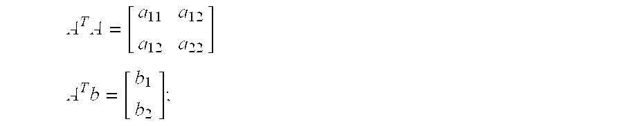
 [ R L ] = ( A T A ) - 1 A T b , with A T A = [ k = 1 n ( I k + I k - 1 ) 2 2 Δ t · k = 1 n ( I k - I k - 1 ) · ( I k + I k - 1 ) 2 Δ t · k = 1 n ( I k - I k - 1 ) · ( I k + I k - 1 ) ( 2 Δ t ) 2 · k = 1 n ( I k - I k - 1 ) 2 ] A T b = [ k = 1 n ( I k + I k - 1 ) · ( V k + V k - 1 ) 2 Δ t · k = 1 n ( I k - I k - 1 ) · ( V k + V k - 1 ) ] . ( 6 )
Figure US06397156-20020528-M00006
Notably, ATA in eq. (6) is a 2×2 symmetric matrix and therefore is relatively easily and quickly inverted. The number of time windows needed to stabilize the algorithm is preferably empirically determined. Furthermore, additional algorithm stabilization is achieved by appropriate normalization of each row in eq. (5). For practical implementation, computing time can be reduced drastically by storing appropriate numbers so that for each new sample the number of calculations is minimized. Specifically, ATA and A Tb may be re-characterized as: A T A = [ a 11 a 12 a 21 a 22 ] A T b = [ b 1 b 2 ] . ( 7 )
Figure US06397156-20020528-M00007
By recognizing that a12=a21, and by storing and updating a11, a12, a22, b1, b2, and Ik+Ik−1,I-Ik−1, and Vk+Vk−1, (k=1 to n) for each new sample, and by recognizing that the time window over which the summations of eq. (6) takes place is m samples wide, the computation of ATA and ATb is preferably accelerated by employing the formulas: a 11 = a 11 + ( I n + I n - 1 ) 2 - ( I n - m + I n - m - 1 ) 2 , a 22 = a 22 + ( 2 Δ t ) 2 · ( ( I n - I n - 1 ) 2 - ( I n - m - I n - m - 1 ) 2 ) , a 12 = a 12 + 2 Δ t · ( ( I n - I n - 1 ) ( I n + I n - 1 ) - ( I n - m - I n - m - 1 ) ( I n - m + I n - m - 1 ) ) , b 1 = b 1 + ( I n - I n - 1 ) ( V n + V n - 1 ) - ( I n - m - I n - m - 1 ) ( V n - m + V n - m - 1 ) , b 2 = b 2 + 2 Δ t · ( ( I n - I n - 1 ) ( V n + V n - 1 ) - ( I n - m - I n - m - 1 ) ( V n - m + V n - m - 1 ) ) . ( 8 )
Figure US06397156-20020528-M00008
In addition, when computing a11, a12, a21, a22, b1, and b2 in accordance with eq. (8), computation time is preferably further reduced by storing particular intermediate calculated data. Accordingly. the present invention can be implemented with real-time performance, and requires less computing time than waveform type algorithms.
Results using data from appropriate simulations show that stabilization over a quarter-cycle is enough to obtain good performance for distance relaying applications. For fault location estimation, the prediction is very accurate when using about a half-cycle. The number of time periods needed for each of these cases depends on the chosen sampling rate. Increasing the sampling rate increases the amount of stored data but not the computing time of the algorithm described by eq. (8).
For a phase-to-ground fault, an impedance relay normally uses a zero sequence compensation current (I0) to account for the ground return voltage drop. This compensation in a faulted current is usually done as follows: I = I phase + k 0 · I 0 , where k 0 = Z 0 - Z 1 Z 1 ( 9 )
Figure US06397156-20020528-M00009
where Z0 and Z1, are defined as the zero sequence impedance and the positive sequence impedance, respectively.
In order to take into account the zero sequence compensation in the case of phase-to-ground fault, the above-described differential equation algorithm is corrected. For this, k0 is separated into real and imaginary parts such that k0=k5+iki. After defining the angular frequency ω and applying basic calculations, eq. (1) changes to the following: V ( t ) = R ( I phase ( t ) + k r I 0 ( t ) + k i ω I 0 ( t ) t ) + L ( I phase ( t ) t + k r I 0 ( t ) t - ω k i I 0 ( t ) ) . ( 10 )
Figure US06397156-20020528-M00010
Like the above equations, eq. (10) leads to a least squares problem that is solved by inverting a 2×2 matrix. All of the above considerations in connection with eqs. (2)-(8) also yield for this case, and therefore need not be further discussed here.
With the present invention, impedance and phasors are estimated by first measuring a number (n>1) of current and voltage samples (Ik, Vk) representative of values of current and voltage waveforms, respectively, at successive instants of time on a conductor in a power system (step 41 of FIG. 4). Such measurements are then employed in connection with eqs. (6)-(8), above, to compute resistance (R) and inductance (L) values in accordance with an equation in which R and L are related to sums of differences in values of successive current and voltage samples (step 42 of FIG. 4). A prescribed power system function is then performed on the basis of the computed R and L values.
Those skilled in the art of protective relaying will recognize that there are a variety of uses for the estimated impedances yielded by the present invention. For example, such impedances may be employed to perform power system protection functions (step 43 in FIG. 4) including level detection for threshold units, direction discrimination, fault distance estimation, out of step detection, and fault location, among others. In addition such impedances may be employed to perform power measurement functions (step 44 in FIG. 4) including voltage, current and power metering, power flow analysis, state estimation, and power system control, among others. It is therefore important that the impedances used in the various processes be accurate. The present invention provides such accurate phasors.
In the foregoing description, it can be seen that the present invention comprises a new and useful impedance measurement system for power transmission lines including series-compensated transmission lines. It will be appreciated by those skilled in the art that changes could be made to the embodiments described above without departing from the broad inventive concepts thereof Thus, for example, except where expressly so limited, the claims are not limited to applications involving three-phase power systems or power systems employing a 50 Hz or 60 Hz frequency. Moreover, the claims are not limited to systems associated with any particular part of a power distribution system, such as a transformer, a feeder, a high power transmission line, etc. It is understood, therefore, that this invention is not limited to the particular embodiments disclosed but it is intended to cover modifications within the spirit and scope of the present invention as defined by the appended claims.

Claims (15)

We claim:
1. A protective relaying method for use in connection with a power system comprising electrical conductors carrying current and voltage waveforms, the method comprising the steps of:
measuring a number (n) of current and voltage samples (Ik, Vk) representative of values of current and voltage waveforms, respectively, at successive instants of time on a conductor in the power system, wherein the number n is an integer greater than 1 and the index k takes on values of 1 to n;
computing resistance (R) and inductance (L) values in accordance with an equation in which R and L are related to sums of differences in values of successive current and voltage samples; and
performing a prescribed power system function based on the computed R and L values,
wherein R and L are determined in accordance with the following equations: [ R L ] = ( A T A ) - 1 A T b , with A T A = [ k = 1 n ( I k + I k - 1 ) 2 2 Δ t · k = 1 n ( I k - I k - 1 ) · ( I k + I k - 1 ) 2 Δ t · k = 1 n ( I k - I k - 1 ) · ( I k + I k - 1 ) ( 2 Δ t ) 2 · k = 1 n ( I k - I k - 1 ) 2 ] A T b = [ k = 1 n ( I k + I k - 1 ) · ( V k + V k - 1 ) 2 Δ t · k = 1 n ( I k - I k - 1 ) · ( V k + V k - 1 ) ] .
Figure US06397156-20020528-M00011
wherein Δt represents the time period separating successive samples.
2. The method of claim 1 wherein, for each new sample, the elements of the matrices ATA and ATb are computed on the basis of previously computed elements.
3. The method of claim 2 wherein ATA and ATb are re-characterized as: A T A = [ a 11 a 12 a 12 a 22 ] A T b = [ b 1 b 2 ] ;
Figure US06397156-20020528-M00012
the method further comprising the steps of:
storing and updating a11, a12, a22, b1, b2, and Ik+Ik−1, Ik−lk−1, and Vk+Vk−1, (K=I to n) for each new sample;
performing the summations of a11, a12, a22, b1, b2, over a time window m samples wide; and
employing the following equations to accelerate the computation of successive values of a11, a12, a22, b1, and b2 based on previous values thereof: a 11 = a 11 + ( I n + I n - 1 ) 2 - ( I n - m + I n - m - 1 ) 2 , a 22 = a 22 + ( 2 Δ t ) 2 · ( ( I n - I n - 1 ) 2 - ( I n - m - I n - m - 1 ) 2 ) , a 12 = a 12 + 2 Δ t · ( ( I n - I n - 1 ) ( I n + I n - 1 ) - ( I n - m - I n - m - 1 ) ( I n - m + I n - m - 1 ) ) , b 1 = b 1 + ( I n - I n - 1 ) ( V n + V n - 1 ) - ( I n - m - I n - m - 1 ) ( V n - m + V n - m - 1 ) , b 2 = b 2 + 2 Δ t · ( ( I n - I n - 1 ) ( V n + V n - 1 ) - ( I n - m - I n - m - 1 ) ( V n - m + V n - m - 1 ) ) .
Figure US06397156-20020528-M00013
4. The method of claim 1 wherein the prescribed power system function is a power system protection function selected from a group consisting of: level detection for threshold units, direction discrimination, fault distance estimation, out of step detection, and fault location.
5. The method of claim 1 wherein the prescribed power system function is a power measurement function selected from a group consisting of: voltage, current and power metering; power flow analysis; state estimation; and power system control.
6. A protective relay for use in connection with a power system comprising electrical conductors carrying current and voltage waveforms, the relay comprising:
a memory storing a number (n) of measured current and voltage samples (Ik, Vk) representative of values of current and voltage waveforms, respectively, at successive instants of time on a conductor in the power system, wherein the number n is an integer greater than 1 and the index k takes on values of 1 to n; and
a processor computing resistance (R) and inductance (L) values in accordance with an equation in which R and L are related to sums of differences in values of successive current and voltage samples;
wherein the relay performs a prescribed power system function based on the computed R and L values,
wherein the processor determines R and L in accordance with the following equations: [ R L ] = ( A T A ) - 1 A T b , with A T A = [ k = 1 n ( I k + I k - 1 ) 2 2 Δ t · k = 1 n ( I k - I k - 1 ) · ( I k + I k - 1 ) 2 Δ t · k = 1 n ( I k - I k - 1 ) · ( I k + I k - 1 ) ( 2 Δ t ) 2 · k = 1 n ( I k - I k - 1 ) 2 ] A T b = [ k = 1 n ( I k + I k - 1 ) · ( V k + V k - 1 ) 2 Δ t · k = 1 n ( I k - I k - 1 ) · ( V k + V k - 1 ) ] .
Figure US06397156-20020528-M00014
wherein Δt represents the time period separating successive samples.
7. The relay of claim 6, wherein, for each new sample, the processor computes the elements of the matrices ATA and ATb on the basis of previously computed elements.
8. The relay of claim 7 wherein the processor re-characterizes ATA and ATb as: A T A = [ a 11 a 12 a 12 a 22 ] A T b = [ b 1 b 2 ] ;
Figure US06397156-20020528-M00015
the processor storing and updating a11, a12, a22, b1, b2, and Ik+Ik−1, Ik-I k−1, and Vk+Vk−1, (k=I to n) for each new sample;
the processor performing the summations of a11, a12, a22, b1, b2, over a time window m samples wide; and
the processor employing the following equations to accelerate the computation of successive values of a11, a12, a22, b1, and b2 based on previous values thereof: a 11 = a 11 + ( I n + I n - 1 ) 2 - ( I n - m + I n - m - 1 ) 2 , a 22 = a 22 + ( 2 Δ t ) 2 · ( ( I n - I n - 1 ) 2 - ( I n - m - I n - m - 1 ) 2 ) , a 12 = a 12 + 2 Δ t · ( ( I n - I n - 1 ) ( I n + I n - 1 ) - ( I n - m - I n - m - 1 ) ( I n - m + I n - m - 1 ) ) , b 1 = b 1 + ( I n - I n - 1 ) ( V n + V n - 1 ) - ( I n - m - I n - m - 1 ) ( V n - m + V n - m - 1 ) , b 2 = b 2 + 2 Δ t · ( ( I n - I n - 1 ) ( V n + V n - 1 ) - ( I n - m - I n - m - 1 ) ( V n - m + V n - m - 1 ) ) .
Figure US06397156-20020528-M00016
9. The relay of claim 6 wherein the prescribed power system function is a power system protection function selected from a group consisting of: level detection for threshold units, direction discrimination, fault distance estimation, out of step detection, and fault location.
10. The relay of claim 6 wherein the prescribed power system function is a power measurement function selected from a group consisting of: voltage, current and power metering; power flow analysis; state estimation; and power system control.
11. A power system comprising electrical conductors carrying current and voltage waveforms and a protective relay comprising:
a memory storing a number (n) of measured current and voltage samples (Ik, Vk) representative of values of current and voltage waveforms, respectively, at successive instants of time on a conductor in the power system, wherein the number n is an integer greater than 1 and the index k takes on values of 1 to n; and
a processor computing resistance (R) and inductance (L) values in accordance with an equation in which R and L are related to sums of differences in values of successive current and voltage samples;
wherein the relay performs a prescribed power system function based on the computed R and L values,
wherein the processor determines R and L in accordance with the following equations: [ R L ] = ( A T A ) - 1 A T b , with A T A = [ k = 1 n ( I k + I k - 1 ) 2 2 Δ t · k = 1 n ( I k - I k - 1 ) · ( I k + I k - 1 ) 2 Δ t · k = 1 n ( I k - I k - 1 ) · ( I k + I k - 1 ) ( 2 Δ t ) 2 · k = 1 n ( I k - I k - 1 ) 2 ] A T b = [ k = 1 n ( I k + I k - 1 ) · ( V k + V k - 1 ) 2 Δ t · k = 1 n ( I k - I k - 1 ) · ( V k + V k - 1 ) ] .
Figure US06397156-20020528-M00017
wherein Δt represents the time period separating successive samples.
12. The power system of claim 11 wherein, for each new sample, the processor computes the elements of the matrices ATA and ATb on the basis of previously computed elements.
13. The power system of claim 12 wherein the processor re-characterizes ATA and ATb as: A T A = [ a 11 a 12 a 12 a 22 ] A T b = [ b 1 b 2 ] ;
Figure US06397156-20020528-M00018
the processor storing and updating a11, a12, a22, b1, b2, and Ik+Ik−1, Ik-I k−1, and Vk+Vk−1, (k=I to n) for each new sample;
the processor performing the summations of a11, a12, a22, b1, b2, over a time window m samples wide; and
the processor employing the following equations to accelerate the computation of successive values of a11, a12, a22, b1, and b2 based on previous values thereof: a 11 = a 11 + ( I n + I n - 1 ) 2 - ( I n - m + I n - m - 1 ) 2 , a 22 = a 22 + ( 2 Δ t ) 2 · ( ( I n - I n - 1 ) 2 - ( I n - m - I n - m - 1 ) 2 ) , a 12 = a 12 + 2 Δ t · ( ( I n - I n - 1 ) ( I n + I n - 1 ) - ( I n - m - I n - m - 1 ) ( I n - m + I n - m - 1 ) ) , b 1 = b 1 + ( I n - I n - 1 ) ( V n + V n - 1 ) - ( I n - m - I n - m - 1 ) ( V n - m + V n - m - 1 ) , b 2 = b 2 + 2 Δ t · ( ( I n - I n - 1 ) ( V n + V n - 1 ) - ( I n - m - I n - m - 1 ) ( V n - m + V n - m - 1 ) ) .
Figure US06397156-20020528-M00019
14. The power system of claim 11 wherein the prescribed power system function is a power system protection function selected from a group consisting of: level detection for threshold units, direction discrimination, fault distance estimation, out of step detection, and fault location.
15. The power system of claim 11 wherein the prescribed power system function is a power measurement function selected from a group consisting of: voltage, current and power metering; power flow analysis; state estimation; and power system control.
US09/192,851 1998-11-17 1998-11-17 Impedance measurement system for power system transmission lines Expired - Fee Related US6397156B1 (en)

Priority Applications (4)

Application Number Priority Date Filing Date Title
US09/192,851 US6397156B1 (en) 1998-11-17 1998-11-17 Impedance measurement system for power system transmission lines
AU12377/00A AU1237700A (en) 1998-11-17 1999-10-27 Impedance measurement system for power system transmission lines
PCT/US1999/025229 WO2000030233A1 (en) 1998-11-17 1999-10-27 Impedance measurement system for power system transmission lines
EP99972381A EP1142076A4 (en) 1998-11-17 1999-10-27 Impedance measurement system for power system transmission lines

Applications Claiming Priority (1)

Application Number Priority Date Filing Date Title
US09/192,851 US6397156B1 (en) 1998-11-17 1998-11-17 Impedance measurement system for power system transmission lines

Publications (1)

Publication Number Publication Date
US6397156B1 true US6397156B1 (en) 2002-05-28

Family

ID=22711298

Family Applications (1)

Application Number Title Priority Date Filing Date
US09/192,851 Expired - Fee Related US6397156B1 (en) 1998-11-17 1998-11-17 Impedance measurement system for power system transmission lines

Country Status (4)

Country Link
US (1) US6397156B1 (en)
EP (1) EP1142076A4 (en)
AU (1) AU1237700A (en)
WO (1) WO2000030233A1 (en)

Cited By (27)

* Cited by examiner, † Cited by third party
Publication number Priority date Publication date Assignee Title
US6713998B2 (en) * 2000-11-06 2004-03-30 Abb Research Ltd Method for measuring the resistance and the inductance of a line
EP1508811A2 (en) * 2003-08-19 2005-02-23 Eaton Corporation Method and apparatus for measuring impedance
US20060066321A1 (en) * 2004-09-30 2006-03-30 Gasperi Michael L AC power line impedance monitoring method and system
US20060229834A1 (en) * 2005-03-30 2006-10-12 Gasperi Michael L Dual connection power line parameter analysis method and system
US20060271992A1 (en) * 2005-05-26 2006-11-30 Texas Instruments Incorporated Method and apparatus for characterizing a load on a data line
WO2007012456A1 (en) * 2005-07-26 2007-02-01 Knorr-Bremse Systeme für Nutzfahrzeuge GmbH Measurement arrangement for measuring the inductance and resistance value of an inductive sensor
US20070236208A1 (en) * 2006-04-07 2007-10-11 Cooper Technologies Company Protective relay device, system and methods for Rogowski coil sensors
US20080265910A1 (en) * 2007-04-30 2008-10-30 Rockwell Automation Technologies, Inc. Line impedance measurement method and system
US20080265912A1 (en) * 2007-04-30 2008-10-30 Rockwell Automation Technologies, Inc. Portable line impedance measurement method and system
US20090183362A1 (en) * 2008-01-18 2009-07-23 Inventec Corporation Method for manufacturing a transmission line equalizer
US20100014197A1 (en) * 2006-07-15 2010-01-21 Deepstreem Technologies Ltd Method and apparatus of detecting and compensating for dc residual fault currents on electrical systems
US7902812B2 (en) 2006-11-06 2011-03-08 Cooper Technologies Company Rogowski coil assembly and methods
CN102033177A (en) * 2010-10-25 2011-04-27 华北电力大学 Method and system for measuring power angle of electric power circuit of distribution network
CN102937676A (en) * 2012-10-25 2013-02-20 福州大学 Method and system for implementing early warning of load harmonic injection pollution
US8395871B2 (en) 2007-02-20 2013-03-12 Abb Technology Ag Device and method for detecting faulted phases in a multi-phase electrical network
US8537516B1 (en) * 2008-12-05 2013-09-17 Musco Corporation Apparatus, method, and system for monitoring of equipment and earth ground systems
US8773829B2 (en) 2012-10-31 2014-07-08 General Electric Company Method and system for power swing detection in a generator
WO2014135680A1 (en) 2013-03-08 2014-09-12 Abb Research Ltd Overcurrent protection device and method
US20140371929A1 (en) * 2013-06-17 2014-12-18 Schweitzer Engineering Laboratories, Inc. Source Impedance Estimation
US9143112B2 (en) 2011-06-30 2015-09-22 Silicon Laboratories Inc. Circuits and methods for providing an impedance adjustment
CN106324347A (en) * 2015-06-16 2017-01-11 云南电网有限责任公司玉溪供电局 T-type connection transmission line power frequency positive-sequence impedance measurement method
WO2018122160A1 (en) * 2016-12-30 2018-07-05 Kamstrup A/S Electricity meter with an impedance learning algorithm
CN110770993A (en) * 2017-06-30 2020-02-07 智能电线股份有限公司 Modular FACTS device with external fault current protection
US10756542B2 (en) 2018-01-26 2020-08-25 Smart Wires Inc. Agile deployment of optimized power flow control system on the grid
US10938314B2 (en) 2018-07-23 2021-03-02 Smart Wires Inc. Early detection of faults in power transmission lines
US10996044B2 (en) * 2012-03-22 2021-05-04 Zhibiao Shao Measurement method for aviation-specific proximity sensor
US20220330411A1 (en) * 2021-04-07 2022-10-13 Yantai Jereh Petroleum Equipment & Technologies Co., Ltd. Fracturing well site system

Citations (11)

* Cited by examiner, † Cited by third party
Publication number Priority date Publication date Assignee Title
US3599044A (en) * 1970-04-30 1971-08-10 Fuji Electric Co Ltd Superhigh-speed relaying system and apparatus for protection of power systems
US4107778A (en) * 1976-02-18 1978-08-15 Hitachi, Ltd. Digital fault-location calculation system
US4228476A (en) * 1977-06-13 1980-10-14 Tokyo Shibaura Denki Kabushiki Kaisha Protective relaying system
US4313169A (en) * 1978-11-13 1982-01-26 Tokyo Denryoku Kabushiki Kaisha Fault detecting system for locating a fault point with a fault resistance separately measured
US4321681A (en) * 1979-09-21 1982-03-23 Westinghouse Electric Corp. Protective relay apparatus
US4438475A (en) * 1982-08-02 1984-03-20 Westinghouse Electric Corp. Ultra-high speed protective relay apparatus and method for providing single pole switching
US4455612A (en) * 1982-01-27 1984-06-19 Iowa State University Research Foundation, Inc. Recursive estimation in digital distance relaying system
US4985843A (en) * 1987-03-03 1991-01-15 Mitsubishi Denki Kabushiki Kaisha Digital locator
US5349490A (en) 1992-10-15 1994-09-20 Schweitzer Engineering Laboratories, Inc. Negative sequence directional element for a relay useful in protecting power transmission lines
US5515227A (en) 1992-10-16 1996-05-07 Schweitzer Engineering Laboratories Inc. Fault identification system for use in protective relays for power transmission lines
US5839093A (en) * 1996-12-31 1998-11-17 Abb Transmit Oy System for locating faults and estimating fault resistance in distribution networks with tapped loads

Family Cites Families (1)

* Cited by examiner, † Cited by third party
Publication number Priority date Publication date Assignee Title
DE4429191A1 (en) * 1994-08-18 1996-02-22 Licentia Gmbh Algorithm for modelling status changes e.g. in electrical power transmission networks

Patent Citations (12)

* Cited by examiner, † Cited by third party
Publication number Priority date Publication date Assignee Title
US3599044A (en) * 1970-04-30 1971-08-10 Fuji Electric Co Ltd Superhigh-speed relaying system and apparatus for protection of power systems
US4107778A (en) * 1976-02-18 1978-08-15 Hitachi, Ltd. Digital fault-location calculation system
US4228476A (en) * 1977-06-13 1980-10-14 Tokyo Shibaura Denki Kabushiki Kaisha Protective relaying system
US4313169A (en) * 1978-11-13 1982-01-26 Tokyo Denryoku Kabushiki Kaisha Fault detecting system for locating a fault point with a fault resistance separately measured
US4321681A (en) * 1979-09-21 1982-03-23 Westinghouse Electric Corp. Protective relay apparatus
US4455612A (en) * 1982-01-27 1984-06-19 Iowa State University Research Foundation, Inc. Recursive estimation in digital distance relaying system
US4438475A (en) * 1982-08-02 1984-03-20 Westinghouse Electric Corp. Ultra-high speed protective relay apparatus and method for providing single pole switching
US4985843A (en) * 1987-03-03 1991-01-15 Mitsubishi Denki Kabushiki Kaisha Digital locator
US5349490A (en) 1992-10-15 1994-09-20 Schweitzer Engineering Laboratories, Inc. Negative sequence directional element for a relay useful in protecting power transmission lines
US5365396A (en) 1992-10-15 1994-11-15 Schweitzer Engineering Laboratories, Inc. Negative sequence directional element for a relay useful in protecting power transmission lines
US5515227A (en) 1992-10-16 1996-05-07 Schweitzer Engineering Laboratories Inc. Fault identification system for use in protective relays for power transmission lines
US5839093A (en) * 1996-12-31 1998-11-17 Abb Transmit Oy System for locating faults and estimating fault resistance in distribution networks with tapped loads

Non-Patent Citations (4)

* Cited by examiner, † Cited by third party
Title
"Microprocessor Relays and Protection Systems," IEEE Tutorial Course, 88EH0269-I-PWR, 1986.
A.D. McInnes and I.F. Morrison, "Real Time Calculation of Resistance and Reactance for Transmission Line Protection by Digital Computer," Elec. Eng. Trans., IE, Australia, vol. EE7, No. 1, pp. 16-23.
Damir Novosel et al., "Algorithms For Locating Faults On Series Compensated Lines Using Neural Network and Deterministic Methods," 96WM 021-6 PWRD, -Approved for presentation at the 1996 IEEE/PES Winter Meeting, Jan. 21-25, 1996, Baltimore, MD.
Damir Novosel et al., "Locating Faults On Series Compensated Lines Using Intelligent Methods," Eng. Int. Syst. vol. 5, No. 4, Dec. 1997, pp. 259-264.

Cited By (50)

* Cited by examiner, † Cited by third party
Publication number Priority date Publication date Assignee Title
US6713998B2 (en) * 2000-11-06 2004-03-30 Abb Research Ltd Method for measuring the resistance and the inductance of a line
AU2004203250B2 (en) * 2003-08-19 2008-10-09 Eaton Corporation Method and apparatus for measuring impedance across pressure joints in a power distribution system
EP1508811A2 (en) * 2003-08-19 2005-02-23 Eaton Corporation Method and apparatus for measuring impedance
EP1508811A3 (en) * 2003-08-19 2005-09-07 Eaton Corporation Method and apparatus for measuring impedance
US20060066321A1 (en) * 2004-09-30 2006-03-30 Gasperi Michael L AC power line impedance monitoring method and system
US7164275B2 (en) * 2004-09-30 2007-01-16 Rockwell Automation Technologies, Inc. AC power line impedance monitoring method and system
US20060229834A1 (en) * 2005-03-30 2006-10-12 Gasperi Michael L Dual connection power line parameter analysis method and system
US7200502B2 (en) * 2005-03-30 2007-04-03 Rockwell Automation Technologies, Inc. Dual connection power line parameter analysis method and system
US20060271992A1 (en) * 2005-05-26 2006-11-30 Texas Instruments Incorporated Method and apparatus for characterizing a load on a data line
US7366623B2 (en) * 2005-05-26 2008-04-29 Texas Instruments Incorporated Method and apparatus for characterizing a load on a data line
WO2007012456A1 (en) * 2005-07-26 2007-02-01 Knorr-Bremse Systeme für Nutzfahrzeuge GmbH Measurement arrangement for measuring the inductance and resistance value of an inductive sensor
US20100020457A1 (en) * 2006-04-07 2010-01-28 Cooper Technologies Company Protective Digital Relay Device
US7902813B2 (en) 2006-04-07 2011-03-08 Cooper Technologies Company Protective digital relay device
US20070236208A1 (en) * 2006-04-07 2007-10-11 Cooper Technologies Company Protective relay device, system and methods for Rogowski coil sensors
US7638999B2 (en) * 2006-04-07 2009-12-29 Cooper Technologies Company Protective relay device, system and methods for Rogowski coil sensors
US8340829B2 (en) * 2006-07-15 2012-12-25 Eaton Industries Manufacturing Gmbh Method and apparatus of detecting and compensating for DC residual fault currents on electrical systems
US20100014197A1 (en) * 2006-07-15 2010-01-21 Deepstreem Technologies Ltd Method and apparatus of detecting and compensating for dc residual fault currents on electrical systems
US7902812B2 (en) 2006-11-06 2011-03-08 Cooper Technologies Company Rogowski coil assembly and methods
US8395871B2 (en) 2007-02-20 2013-03-12 Abb Technology Ag Device and method for detecting faulted phases in a multi-phase electrical network
US7671606B2 (en) * 2007-04-30 2010-03-02 Rockwell Automation Technologies, Inc. Portable line impedance measurement method and system
US20080265910A1 (en) * 2007-04-30 2008-10-30 Rockwell Automation Technologies, Inc. Line impedance measurement method and system
US7616010B2 (en) * 2007-04-30 2009-11-10 Rockwell Automation Technologies, Inc. Line impedance measurement method and system
US20080265912A1 (en) * 2007-04-30 2008-10-30 Rockwell Automation Technologies, Inc. Portable line impedance measurement method and system
US7703202B2 (en) * 2008-01-18 2010-04-27 Inventec Corporation Method for manufacturing a transmission line equalizer
US20090183362A1 (en) * 2008-01-18 2009-07-23 Inventec Corporation Method for manufacturing a transmission line equalizer
US8537516B1 (en) * 2008-12-05 2013-09-17 Musco Corporation Apparatus, method, and system for monitoring of equipment and earth ground systems
CN102033177A (en) * 2010-10-25 2011-04-27 华北电力大学 Method and system for measuring power angle of electric power circuit of distribution network
CN102033177B (en) * 2010-10-25 2014-05-07 华北电力大学 Method and system for measuring power angle of electric power circuit of distribution network
US9143112B2 (en) 2011-06-30 2015-09-22 Silicon Laboratories Inc. Circuits and methods for providing an impedance adjustment
US9793873B2 (en) 2011-06-30 2017-10-17 Silicon Laboratories Inc. Circuits and methods for providing an impedance adjustment
US10996044B2 (en) * 2012-03-22 2021-05-04 Zhibiao Shao Measurement method for aviation-specific proximity sensor
CN102937676B (en) * 2012-10-25 2014-12-10 福州大学 Method and system for implementing early warning of load harmonic injection pollution
CN102937676A (en) * 2012-10-25 2013-02-20 福州大学 Method and system for implementing early warning of load harmonic injection pollution
US8773829B2 (en) 2012-10-31 2014-07-08 General Electric Company Method and system for power swing detection in a generator
US10027105B2 (en) 2013-03-08 2018-07-17 Abb Research Ltd. Overcurrent protection device and method
WO2014135680A1 (en) 2013-03-08 2014-09-12 Abb Research Ltd Overcurrent protection device and method
US20140371929A1 (en) * 2013-06-17 2014-12-18 Schweitzer Engineering Laboratories, Inc. Source Impedance Estimation
CN106324347B (en) * 2015-06-16 2019-01-25 云南电网有限责任公司玉溪供电局 T-type wiring transmission line power frequency positive sequence impedance measurement method
CN106324347A (en) * 2015-06-16 2017-01-11 云南电网有限责任公司玉溪供电局 T-type connection transmission line power frequency positive-sequence impedance measurement method
WO2018122160A1 (en) * 2016-12-30 2018-07-05 Kamstrup A/S Electricity meter with an impedance learning algorithm
US10666038B2 (en) * 2017-06-30 2020-05-26 Smart Wires Inc. Modular FACTS devices with external fault current protection
CN110770993A (en) * 2017-06-30 2020-02-07 智能电线股份有限公司 Modular FACTS device with external fault current protection
US11309701B2 (en) 2017-06-30 2022-04-19 Smart Wires Inc. Modular FACTS devices with external fault current protection
US11888308B2 (en) 2017-06-30 2024-01-30 Smart Wires Inc. Modular facts devices with external fault current protection
US10756542B2 (en) 2018-01-26 2020-08-25 Smart Wires Inc. Agile deployment of optimized power flow control system on the grid
US10938314B2 (en) 2018-07-23 2021-03-02 Smart Wires Inc. Early detection of faults in power transmission lines
US20220330411A1 (en) * 2021-04-07 2022-10-13 Yantai Jereh Petroleum Equipment & Technologies Co., Ltd. Fracturing well site system
US11596047B2 (en) * 2021-04-07 2023-02-28 Yantai Jereh Petroleum Equipments Technologies Co., Ltd. Fracturing well site system
US11683878B2 (en) 2021-04-07 2023-06-20 Yantai Jereh Petroleum Equipment & Technologies Co., Ltd. Fracturing well site system
US11729893B2 (en) 2021-04-07 2023-08-15 Yantai Jereh Petroleum Equipment & Technologies Co., Ltd. Fracturing well site system

Also Published As

Publication number Publication date
EP1142076A4 (en) 2005-06-15
EP1142076A1 (en) 2001-10-10
WO2000030233A1 (en) 2000-05-25
AU1237700A (en) 2000-06-05

Similar Documents

Publication Publication Date Title
US6397156B1 (en) Impedance measurement system for power system transmission lines
US11022655B2 (en) Method and control system for faulted phase detection
US10310005B2 (en) Time-domain distance line protection of electric power delivery systems
US10090664B2 (en) Time-domain directional line protection of electric power delivery systems
EP2686691B1 (en) A method for detecting earth faults
US7514933B2 (en) System and method for determining location of phase-to-earth fault
US6584417B1 (en) Method and directional element for fault direction determination in a capacitance-compensated line
US5455776A (en) Automatic fault location system
US5446387A (en) Method and a device for determining a fault on a transmission line
US4878142A (en) High resistance ground fault protection
EP1020729B1 (en) Fault detection for power lines
Chowdhury et al. Power system fault detection and state estimation using Kalman filter with hypothesis testing
WO1995024014A2 (en) One-terminal data fault location system
Suryanarayana et al. Directional relaying using parameter estimation approach
Bainy et al. Enhanced generalized alpha plane for numerical differential protection applications
CN111007357B (en) Sag domain identification method considering load voltage sag tolerance capacity curve
US11594876B2 (en) Accelerated zone-2 protection for transmission lines
US6336059B1 (en) Reach-measurement method for distance relays and fault locators on series-compensated transmission lines using local information
US11016136B2 (en) Method and control system for fault direction detection
Bollen Additions to the method of critical distances for stochastic assessment of voltage sags
Joong-Rin et al. Two terminals numerical algorithm for distance protection, fault location and acing faults recognition based on synchronized phasors
Rao et al. Adaptive Fault Location Algorithm for Series Compensated Line Using Relay data
Patel et al. Reliable detection of internal faults and faulted-phase on transmission lines using instantaneous current
Choudry POWER STREAM From
TAILOR PERFORMANCE INVESTIGATION AND PROTECTION OF TRANSMISSION LINE USING DIGITAL DISTANCE RELAY

Legal Events

Date Code Title Description
AS Assignment

Owner name: ABB POWER T&D COMPANY INC., NORTH CAROLINA

Free format text: ASSIGNMENT OF ASSIGNORS INTEREST;ASSIGNORS:BACHMANN, BERNHARD;NOVOSEL, DAMIR;HART, DAVID G.;AND OTHERS;REEL/FRAME:009718/0524;SIGNING DATES FROM 19981215 TO 19990104

AS Assignment

Owner name: ABB POWER T&D COMPANY INC., NORTH CAROLINA

Free format text: ASSIGNMENT OF ASSIGNORS INTEREST;ASSIGNORS:BACHMANN, BERNHARD;HART, DAVID G.;HU, YI;AND OTHERS;REEL/FRAME:010568/0397;SIGNING DATES FROM 19990909 TO 19991206

FEPP Fee payment procedure

Free format text: PAYOR NUMBER ASSIGNED (ORIGINAL EVENT CODE: ASPN); ENTITY STATUS OF PATENT OWNER: LARGE ENTITY

FPAY Fee payment

Year of fee payment: 4

FPAY Fee payment

Year of fee payment: 8

REMI Maintenance fee reminder mailed
LAPS Lapse for failure to pay maintenance fees
STCH Information on status: patent discontinuation

Free format text: PATENT EXPIRED DUE TO NONPAYMENT OF MAINTENANCE FEES UNDER 37 CFR 1.362

FP Lapsed due to failure to pay maintenance fee

Effective date: 20140528