US6496158B1 - Intermodulation grating lobe suppression method - Google Patents
Intermodulation grating lobe suppression method Download PDFInfo
- Publication number
- US6496158B1 US6496158B1 US09/968,190 US96819001A US6496158B1 US 6496158 B1 US6496158 B1 US 6496158B1 US 96819001 A US96819001 A US 96819001A US 6496158 B1 US6496158 B1 US 6496158B1
- Authority
- US
- United States
- Prior art keywords
- intermodulation
- spacing
- view
- field
- antenna elements
- Prior art date
- Legal status (The legal status is an assumption and is not a legal conclusion. Google has not performed a legal analysis and makes no representation as to the accuracy of the status listed.)
- Expired - Lifetime
Links
Images


Classifications
-
- H—ELECTRICITY
- H01—ELECTRIC ELEMENTS
- H01Q—ANTENNAS, i.e. RADIO AERIALS
- H01Q25/00—Antennas or antenna systems providing at least two radiating patterns
-
- H—ELECTRICITY
- H01—ELECTRIC ELEMENTS
- H01Q—ANTENNAS, i.e. RADIO AERIALS
- H01Q21/00—Antenna arrays or systems
- H01Q21/06—Arrays of individually energised antenna units similarly polarised and spaced apart
- H01Q21/22—Antenna units of the array energised non-uniformly in amplitude or phase, e.g. tapered array or binomial array
-
- H—ELECTRICITY
- H01—ELECTRIC ELEMENTS
- H01Q—ANTENNAS, i.e. RADIO AERIALS
- H01Q3/00—Arrangements for changing or varying the orientation or the shape of the directional pattern of the waves radiated from an antenna or antenna system
- H01Q3/26—Arrangements for changing or varying the orientation or the shape of the directional pattern of the waves radiated from an antenna or antenna system varying the relative phase or relative amplitude of energisation between two or more active radiating elements; varying the distribution of energy across a radiating aperture
- H01Q3/30—Arrangements for changing or varying the orientation or the shape of the directional pattern of the waves radiated from an antenna or antenna system varying the relative phase or relative amplitude of energisation between two or more active radiating elements; varying the distribution of energy across a radiating aperture varying the relative phase between the radiating elements of an array
- H01Q3/34—Arrangements for changing or varying the orientation or the shape of the directional pattern of the waves radiated from an antenna or antenna system varying the relative phase or relative amplitude of energisation between two or more active radiating elements; varying the distribution of energy across a radiating aperture varying the relative phase between the radiating elements of an array by electrical means
- H01Q3/36—Arrangements for changing or varying the orientation or the shape of the directional pattern of the waves radiated from an antenna or antenna system varying the relative phase or relative amplitude of energisation between two or more active radiating elements; varying the distribution of energy across a radiating aperture varying the relative phase between the radiating elements of an array by electrical means with variable phase-shifters
Definitions
- the invention relates to the field of antenna communication systems. More particularly, the present invention relates to phase array antenna systems communicating dual frequency signals generating intermodulation grating lobes.
- Communication systems use antennas for transmitting and receiving communication signals.
- the communication systems can use a variety of antenna systems having transmitter and receiver antennas for defining antenna gain patterns with maximas for directional transmitting and receiving the communication signals.
- One type of antenna system is the active transmit phased arrays having multiple directional antenna elements using beam steering.
- the phased array antenna has a plurality of individual antenna elements lying in plane. Each antenna element broadcasts one or more steered communication signals eliminating the need for multiple apertures.
- Each array element has a respective phase offset for each signal for steering the respective antenna beams in a desired direction toward communication receivers.
- the transmission of the multiple communication signals create unwanted intermodulation products in power amplifiers that produce gain patterns appearing as unwanted signal at intermodulation frequencies in secondary intermodulation main beams and grating lobes in the antenna gain pattern.
- Transmitter power amplifier linearizers and power back-off methods are used to reduce signal distortion. While solid state power amplifier linearizers and power back-off techniques can lower the levels of the unwanted intermodulation products, such techniques lower the array efficiency. It is desirable to control the phased array elements with grating lobe suppression for reduced signal distortion during signal transmission that may use saturated power amplifiers and linearization methods.
- Active phased arrays have solid state power amplifiers at each array element. These solid state power amplifiers are nonlinear devices that produce the unwanted intermodulation products when multiple signals are introduced.
- the intermodulation frequencies are spaced according to the difference between the frequencies. For example, when two transmit carrier frequencies f 1 and f 2 are used for broadcasting signals with two primary main beams creating unwanted intermodulation frequencies at 2f 1 ⁇ f 2 and 2f 2 ⁇ f 1 .
- the phased array produces antenna patterns at the intermodulation frequencies.
- the secondary intermodulation main beams of the intermodulation product patterns are steered according to the difference in the pointing angles of the primary main beams.
- the phased array antenna field of view contains the two primary main beams and may contain intermodulation grating lobe beams depending on the difference in pointing angles of the two primary main beam patterns.
- the secondary intermodulation main beams and intermodulation grating lobe beam may appear within the filed of view of the phase array antenna.
- the primary main beams are widely spaced, then a special condition occurs where the secondary intermodulation main beams advantageously appear outside the field of view and the intermodulation grating lobe beams disadvantageously appear within the field of view.
- the intermodulation grating lobe beam are in the field of view, then the intermodulation grating lobe beams are unwanted interference generated at the intermodulation frequencies.
- An object of the invention is to provide a method for reducing interference generated at intermodulation frequencies.
- Another object of the invention is to provide a method for suppressing intermodulation grating lobe beams at the intermodulation frequencies.
- Another object of the invention is to provide a method for suppressing intermodulation grating lobes in phased array antenna systems.
- Still another object of the invention is to provide a method for reducing transmitted interference signals generated at intermodulation frequencies.
- Yet another object of the invention is to provide a method for suppressing intermodulation grating lobes in phased array antenna systems by regular spacing of phase array antenna elements.
- the present invention is directed to a method for reducing the amplitude level of intermodulation grating lobes in the field of view of a phased array antenna system by regular spacing of subarrays each having a plurality of phased array antenna elements and by interposing predetermined regular spacing between the subarray antenna elements within each subarray.
- the secondary intermodulation main beams are disposed off of the field of view, but the remaining intermodulation grating lobes beams still appear within the field of view, but at suppressed amplitudes levels.
- the regular spacing of the subarrays and the regular spacing of the phased array antenna elements within each subarray reduces, that is, suppresses the intermodulation grating lobe beams that may appear in the field of view.
- FIG. 1 is layout diagram of four subarrays of a phase array antenna system having a gapped array of subarrays.
- FIG. 2 is graph of the field of view antenna pattern of a phased array antenna having primary main beams and intermodulation grating lobe beams.
- FIG. 3 is a schematic of a subarray beam steering system.
- phased array antenna system is segmented into four regularly spaced subarrays 10 a, 10 b, 10 c, and 10 d, each having 3 ⁇ 3 regularly spaced antenna elements, one of which elements is designated as phased array antenna element 12 , for a total of thirty six phased array elements arranged in quadrants.
- the subarray elements 12 are regularly evenly spaced with a spacing gap d between the elements within the each subarray 10 a through 10 d.
- the subarrays 10 a through 10 d are regularly spaced in the quadrants and having a gap between the quadrants at a spacing of a distance of d+ ⁇ d with a gap of ⁇ d, whereas each of the antenna elements 12 are regularly spaced at the distance d within each subarray 10 a through 10 d.
- the two carrier frequencies f 1 and f 2 are respectively used for communicating respective communication signals to two respective communications receivers, not shown.
- the phased array elements are phased for generating two primary main beams used to communicate respective communication signals having respective modulated carriers at the carrier frequencies f 1 and f 2 .
- the use of the two frequencies f 1 and f 2 create transmitted interfering signals at intermodulation frequencies 2f 1 ⁇ f 2 and 2f 2 ⁇ f 1 appearing as intermodulation grating lobe beam.
- the intermodulation grating lobe beams are suppressed within a field of view of the phased array antenna system.
- the primary main beams f 1 and f 2 are in the exemplar form steered off center of the field of view for communicating to respective receivers.
- the field of view may be a view of the earth from a geostationary communications satellite.
- the field of view may be, for example, eighteen degrees.
- the intermodulation grating lobe beams communicating interfering signals at the intermodulation frequencies 2f 2 ⁇ f 1 and 2f 1 ⁇ f 2 are a function of the spacing of the subarrays and the spacing of the phased array elements.
- the amplitude of the intermodulation grating lobes and consequently the amplitude of the interfering signals at the intermodulation frequencies 2f 2 ⁇ f 1 and 2f 1 ⁇ f 2 can be reduce when each array element is regularly spaced within the subarray and when there is a gap between the subarrays for regularly spacing the subarrays.
- the amplitude a( ⁇ , ⁇ ) defines the total antenna pattern of the entire array and is a function of the regular spacing of the subarrays and the regular space of the element of each subarray as defined by a beam pattern equation.
- a ( ⁇ , ⁇ ) a subarray ( ⁇ , ⁇ ) ⁇ a array ( ⁇ , ⁇ )
- the term a subarray ( ⁇ , ⁇ ) indicates a subarray of elements.
- the term a array ( ⁇ , ⁇ ) indicates an array of elements where each element is a subarrays of antenna elements.
- the term a( ⁇ , ⁇ ) is the array pattern of the regularly spaced array comprising the subarrays where the element of the a array ( ⁇ , ⁇ ) array are the subarrays.
- the angle ⁇ is a coelevation angle off a vertical axis to an x-y plane of the phase array antenna, and, the angle ⁇ is an azimuth angle in the x-y plane of the phased array antenna.
- the beam pattern equation can be used to compute the beam amplitude profile of any one of the primary main beams or the intermodulation grating lobe beams.
- the a subarray ( ⁇ , ⁇ ) pattern is separable in the x and y axes as defined by subarray equations.
- a x and a y are the patterns of x directed and y directed linear arrays
- I m and J n are the excitations of the x directed and y directed linear arrays
- k is the wave number equal to ⁇ /c
- ⁇ is the carrier frequency such as f 1 , f 2 , 2f 1 ⁇ f 2 and 2f 2 ⁇ f 1 in radians and c is the speed of light
- d is the interelemental spacing dimension
- ⁇ o and ⁇ o are the primary main beam pattern coelevation and azimuth angles.
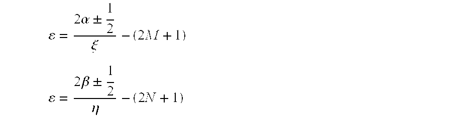
- the Intermodulation grating lobes occur as defined by grating lobe equations.
- ⁇ and ⁇ are integers enumerating an infinite number of possible grating lobes
- ⁇ g and ⁇ g are the intermodulation grating lobe pattern angles
- the array pattern is defined by an array pattern equation.
- ⁇ ( ⁇ , ⁇ ) ⁇ 4 ⁇ cos ⁇ [ k ⁇ ( M + 1 2 + ⁇ 2 ) ⁇ ⁇ d ⁇ ( sin ⁇ ⁇ ⁇ ⁇ ⁇ cos ⁇ ⁇ ⁇ - sin ⁇ ⁇ ⁇ ⁇ o ⁇ cos ⁇ ⁇ ⁇ o ) ] ⁇ ⁇ cos ⁇ [ k ⁇ ( N + 1 2 + ⁇ 2 ) ⁇ ⁇ d ⁇ ( sin ⁇ ⁇ ⁇ ⁇ sin ⁇ ⁇ ⁇ - sin ⁇ ⁇ ⁇ o ⁇ sin ⁇ ⁇ ⁇ o ) ]
- ⁇ is the subarray gap factor.
- the product ⁇ d indicates the subarray gap size.
- phased elemental contribution to the intermodulation grating lobes tend to cancel each other in the direction of the intermodulation beam angles of ⁇ g ⁇ g , and, the elemental contribution to the primary main beams tend to add in the direction ⁇ o and ⁇ o , thereby effectively suppressing the intermodulation grating lobes as an effective null.
- the method can be used in phased array antenna communication systems where the array transmits multiple signals in two or more steered beams.
- One application is a time division multiple accessing (TDMA) satellite communication system where the downlink beams are repositioned to different user locations at fixed time intervals.
- TDMA time division multiple accessing
- exploitation of the suppression method is through scheduling the beams to maximize beam separation. With maximized beam separation, the intermodulation product grating lobes that appear within the field of view will be suppressed.
- Another potential application is a scanning radar antenna where the beams are steered in a regular scan pattern. This scanning radar application of the suppression method can occur by starting the scanning beams at different parts of the scan pattern and thereby introducing a delay between the scans.
- the method is applied for suppressing intermodulation grating lobes in phase array antenna systems.
- the technique places a gap between the subarrays and the array elements.
- the subarray gap size is preferably one-half the element spacing in X-Y directions. Suppression for most cases is approximately between 2.6 dB and 5.1 dB.
- the technique is useful for a special condition where the primary main beams are widely spaced and the intermodulation pattern grating lobes appear within the field of view.
- the array configuration places gaps between the subarrays to suppress intermodulation grating lobes in the field of view.
- the patterns of an exemplar 18 ⁇ 18 element array with uniform illumination have the intermodulation grating lobes steered into a 17° degree field of view.
- the grating lobes in the field of view are reduced.
- a side effect of this grating lobe suppression method is that the sidelobes of the primary patterns increase by approximately 1.0 dB and the array efficiency is reduced on the order of 0.01 dB.
- a array of 18 ⁇ 18 elements form four subarrays of 9 ⁇ 9 elements each.
- 18 ⁇ 18 elements form four subarrays of 9 ⁇ 9 elements each.
- a beam steering processor 20 conventionally controls a bank phase shifters 22 having a plurality of individual phase shifters 24 a, 24 b, 24 c, 24 d, 24 e, 24 f, 24 g, and 24 h.
- the two carrier frequencies f 1 and f 2 are modulated carrier signals 23 a and 23 b, respectively communicating data modulating the two carrier frequencies.
- the two modulated carriers 23 a and 23 b are fed into the phase shifters 22 to a plurality of pairs of phase shifters, for example, the pair of shifters 24 a and 24 b for providing respective phase shifted outputs.
- phase shifted outputs are summed by a bank of summers 26 including individual summers 27 a, 27 b, 27 c and 27 d.
- Each pair of phase shifted outputs of the phase shifter 22 such as phase shifters 24 a and 24 b, are summed by the summer 26 , for example, summer 27 a, for providing dual carrier signals fed into a bank of amplifiers 28 having amplifiers 29 a, 29 b, 29 c, and 29 d.
- summed modulated carrier signal from the summer 27 is amplified by amplifier 29 a.
- the amplified carrier frequency signals from the amplifiers 28 are respectively communicated to the antenna elements 30 having elements 31 a, 31 b, 31 c and 31 d.
- amplified modulated carrier signal from amplifier 29 a is communicated to antenna element 31 a for transmission.
- the antenna elements 30 collectively function to define the field of view of the antenna pattern, an example of which is shown in FIG. 2 .
- the amplifiers 28 are not perfect amplifiers such that intermodulation products are produced when amplifying the modulated carrier signals f 1 and f 2 .
- the regular spacing of the subarrays 10 a through 10 d with regular elemental spacing within each subarray serves to reduce the intermodulation grating lobes 2f 1 ⁇ f 2 and 2f 2 ⁇ f 1 .
- Active transmit phased arrays with two frequencies have intermodulation products that produce unwanted beams.
- Solid state amplifiers at each array element produce intermodulation products when two signals are introduced.
- the intermodulation main beam is steered according to the difference in the pointing angles of the primary main beams.
- the antenna field of view may contain an intermodulation main beam or an intermodulation grating lobe.
- the method places a gap between the subarrays such that the array pattern has a null in the direction of the subarray intermodulation grating lobe.
- the method takes advantage of existing subarray architectures.
- a gap between the subarrays is a modification of the elemental and subarray spacing within the array.
- the method is independent of wavelength and functions at all frequencies.
- the grating lobe suppression method can be used in array applications where the array transmits two frequencies in two or more steered beams.
- downlink beams are repositioned at fixed time intervals.
- the suppression method is used for scheduling beams to maximize beam separation.
- the intermodulation product grating lobes that appear within the field of view are suppressed.
- beams are steered in a regular scan pattern.
- the suppression method can introduce a delay between the scans.
- the suppression method for intermodulation grating lobes takes advantage of gaps disposed between the subarrays. The gap size can be for example one-half the element spacing for grating lobe suppression.
Abstract
Description


Claims (9)
Priority Applications (1)
| Application Number | Priority Date | Filing Date | Title |
|---|---|---|---|
| US09/968,190 US6496158B1 (en) | 2001-10-01 | 2001-10-01 | Intermodulation grating lobe suppression method |
Applications Claiming Priority (1)
| Application Number | Priority Date | Filing Date | Title |
|---|---|---|---|
| US09/968,190 US6496158B1 (en) | 2001-10-01 | 2001-10-01 | Intermodulation grating lobe suppression method |
Publications (1)
| Publication Number | Publication Date |
|---|---|
| US6496158B1 true US6496158B1 (en) | 2002-12-17 |
Family
ID=25513876
Family Applications (1)
| Application Number | Title | Priority Date | Filing Date |
|---|---|---|---|
| US09/968,190 Expired - Lifetime US6496158B1 (en) | 2001-10-01 | 2001-10-01 | Intermodulation grating lobe suppression method |
Country Status (1)
| Country | Link |
|---|---|
| US (1) | US6496158B1 (en) |
Cited By (35)
| Publication number | Priority date | Publication date | Assignee | Title |
|---|---|---|---|---|
| US20050146473A1 (en) * | 2004-01-07 | 2005-07-07 | Skygate International Technology Nv | Mobile antenna system for satellite communications |
| US20050285785A1 (en) * | 2004-06-10 | 2005-12-29 | Harris Corporation, Corporation Of The State Of Delaware | Communications system including phased array antenna providing nulling and related methods |
| US20060057977A1 (en) * | 2004-09-15 | 2006-03-16 | Aviation Communication & Surveillance Systems Llc | Pulse transmitters having multiple outputs in phase relationship and methods of operation |
| US20060244669A1 (en) * | 2003-02-18 | 2006-11-02 | Starling Advanced Communications Ltd. | Low profile antenna for satellite communication |
| US20060284775A1 (en) * | 2004-06-10 | 2006-12-21 | Raysat, Inc. | Applications for low profile two way satellite antenna system |
| US20080018545A1 (en) * | 2004-01-07 | 2008-01-24 | Ilan Kaplan | Applications for low profile two-way satellite antenna system |
| US20080174473A1 (en) * | 2004-09-15 | 2008-07-24 | Smith Mark D | Systems and methods for using a TCAS directional antenna for omnidirectional transmission |
| US20080189747A1 (en) * | 2004-08-26 | 2008-08-07 | Raysat Antenna Systems, L.L.C. | System For Concurrent Mobile Two-Way Data Communications And TV Reception |
| US7595762B2 (en) | 2005-10-16 | 2009-09-29 | Starling Advanced Communications Ltd. | Low profile antenna |
| US7663566B2 (en) | 2005-10-16 | 2010-02-16 | Starling Advanced Communications Ltd. | Dual polarization planar array antenna and cell elements therefor |
| US20110215985A1 (en) * | 2004-06-10 | 2011-09-08 | Raysat Antenna Systems, L.L.C. | Applications for Low Profile Two Way Satellite Antenna System |
| US20110217976A1 (en) * | 2004-01-07 | 2011-09-08 | Raysat Antenna Systems, L.L.C. | Antenna System |
| US20130121342A1 (en) * | 2011-11-16 | 2013-05-16 | Samsung Electronics Co. Ltd. | Method and apparatus for transmitting and receiving signals in multi-antenna communication system |
| US20130148636A1 (en) * | 2011-12-12 | 2013-06-13 | Apple Inc. | Wireless electronic device with antenna switching circuitry |
| US8643543B2 (en) | 2010-09-10 | 2014-02-04 | The Aerospace Corporation | Phased array antenna system with intermodulation beam nulling |
| US8866686B1 (en) | 2009-03-25 | 2014-10-21 | Raytheon Company | Methods and apparatus for super-element phased array radiator |
| US8907842B1 (en) | 2009-03-25 | 2014-12-09 | Raytheon Company | Method and apparatus for attenuating a transmitted feedthrough signal |
| US8964891B2 (en) | 2012-12-18 | 2015-02-24 | Panasonic Avionics Corporation | Antenna system calibration |
| US9070964B1 (en) | 2011-12-19 | 2015-06-30 | Raytheon Company | Methods and apparatus for volumetric coverage with image beam super-elements |
| US9086476B1 (en) | 2009-03-25 | 2015-07-21 | Raytheon Company | Method and apparatus for rejecting intermodulation products |
| US9373888B1 (en) | 2009-03-25 | 2016-06-21 | Raytheon Company | Method and apparatus for reducing sidelobes in large phased array radar with super-elements |
| US9583829B2 (en) | 2013-02-12 | 2017-02-28 | Panasonic Avionics Corporation | Optimization of low profile antenna(s) for equatorial operation |
| US10263344B2 (en) * | 2015-10-30 | 2019-04-16 | Mitsubishi Electric Corporation | High-frequency antenna module and array antenna device |
| US10281571B2 (en) | 2014-08-21 | 2019-05-07 | Raytheon Company | Phased array antenna using stacked beams in elevation and azimuth |
| US10356940B2 (en) * | 2013-05-31 | 2019-07-16 | Bae Systems Plc | In and relating to antenna systems |
| US10365364B1 (en) | 2018-05-18 | 2019-07-30 | Zendar Inc. | Systems and methods for detecting objects |
| US10371797B1 (en) * | 2018-05-23 | 2019-08-06 | Zendar Inc. | Systems and methods for enhancing target detection |
| CN110095771A (en) * | 2018-01-31 | 2019-08-06 | 西弗尔斯伊玛有限公司 | Radar beam manufacturing process |
| US10615516B2 (en) * | 2015-03-25 | 2020-04-07 | Panasonic Corporation | Radar device |
| US10700444B2 (en) | 2016-07-06 | 2020-06-30 | Industrial Technology Research Institute | Multi-beam phased antenna structure and controlling method thereof |
| JPWO2020241271A1 (en) * | 2019-05-31 | 2020-12-03 | ||
| WO2021008977A1 (en) * | 2019-07-18 | 2021-01-21 | Thales | Multi-panel array antenna |
| US11152700B2 (en) * | 2018-04-16 | 2021-10-19 | Phase Sensitive Innovations, Inc. | Beam steering antenna transmitter, multi-user antenna MIMO transmitter and related methods of communication |
| US11275145B2 (en) * | 2015-10-07 | 2022-03-15 | Denso Corporation | Antenna device and target detecting device |
| US11531083B2 (en) | 2017-06-02 | 2022-12-20 | Teledyne Flir, Llc | Ranging systems and methods with staggered multichannel transducers |
Citations (2)
| Publication number | Priority date | Publication date | Assignee | Title |
|---|---|---|---|---|
| US5204686A (en) * | 1988-04-06 | 1993-04-20 | Trw Inc. | RF Feed array |
| US6256290B1 (en) * | 1996-09-13 | 2001-07-03 | Lucent Technologies, Inc. | Multi-carrier CDMA transmission system with frequency and transmit diversity |
-
2001
- 2001-10-01 US US09/968,190 patent/US6496158B1/en not_active Expired - Lifetime
Patent Citations (2)
| Publication number | Priority date | Publication date | Assignee | Title |
|---|---|---|---|---|
| US5204686A (en) * | 1988-04-06 | 1993-04-20 | Trw Inc. | RF Feed array |
| US6256290B1 (en) * | 1996-09-13 | 2001-07-03 | Lucent Technologies, Inc. | Multi-carrier CDMA transmission system with frequency and transmit diversity |
Cited By (70)
| Publication number | Priority date | Publication date | Assignee | Title |
|---|---|---|---|---|
| US20060244669A1 (en) * | 2003-02-18 | 2006-11-02 | Starling Advanced Communications Ltd. | Low profile antenna for satellite communication |
| US7768469B2 (en) | 2003-02-18 | 2010-08-03 | Starling Advanced Communications Ltd. | Low profile antenna for satellite communication |
| US7999750B2 (en) | 2003-02-18 | 2011-08-16 | Starling Advanced Communications Ltd. | Low profile antenna for satellite communication |
| US7629935B2 (en) | 2003-02-18 | 2009-12-08 | Starling Advanced Communications Ltd. | Low profile antenna for satellite communication |
| US20080018545A1 (en) * | 2004-01-07 | 2008-01-24 | Ilan Kaplan | Applications for low profile two-way satellite antenna system |
| US20050146473A1 (en) * | 2004-01-07 | 2005-07-07 | Skygate International Technology Nv | Mobile antenna system for satellite communications |
| US6999036B2 (en) * | 2004-01-07 | 2006-02-14 | Raysat Cyprus Limited | Mobile antenna system for satellite communications |
| US20110217976A1 (en) * | 2004-01-07 | 2011-09-08 | Raysat Antenna Systems, L.L.C. | Antenna System |
| US7385562B2 (en) * | 2004-01-07 | 2008-06-10 | Raysat Antenna Systems, L.L.C. | Mobile antenna system for satellite communications |
| US8761663B2 (en) | 2004-01-07 | 2014-06-24 | Gilat Satellite Networks, Ltd | Antenna system |
| US20080246676A1 (en) * | 2004-01-07 | 2008-10-09 | Raysat Antenna Systems, L.L.C. | Mobile Antenna System For Satellite Communications |
| US7911400B2 (en) | 2004-01-07 | 2011-03-22 | Raysat Antenna Systems, L.L.C. | Applications for low profile two-way satellite antenna system |
| US20050259021A1 (en) * | 2004-01-07 | 2005-11-24 | Raysat Cyprus Limited | Mobile antenna system for satellite communications |
| US7068219B2 (en) * | 2004-06-10 | 2006-06-27 | Harris Corporation | Communications system including phased array antenna providing nulling and related methods |
| US20060284775A1 (en) * | 2004-06-10 | 2006-12-21 | Raysat, Inc. | Applications for low profile two way satellite antenna system |
| US20110215985A1 (en) * | 2004-06-10 | 2011-09-08 | Raysat Antenna Systems, L.L.C. | Applications for Low Profile Two Way Satellite Antenna System |
| US20050285785A1 (en) * | 2004-06-10 | 2005-12-29 | Harris Corporation, Corporation Of The State Of Delaware | Communications system including phased array antenna providing nulling and related methods |
| US20080189747A1 (en) * | 2004-08-26 | 2008-08-07 | Raysat Antenna Systems, L.L.C. | System For Concurrent Mobile Two-Way Data Communications And TV Reception |
| US7554482B2 (en) | 2004-09-15 | 2009-06-30 | Aviation Communication & Surveillance Systems | Systems and methods for using a TCAS directional antenna for omnidirectional transmission |
| US7515097B2 (en) | 2004-09-15 | 2009-04-07 | Aviation Communication & Surveillance Systems | Pulse transmitters having multiple outputs in phase relationship and methods of operation |
| US20080174473A1 (en) * | 2004-09-15 | 2008-07-24 | Smith Mark D | Systems and methods for using a TCAS directional antenna for omnidirectional transmission |
| US7345626B2 (en) | 2004-09-15 | 2008-03-18 | Aviation Communication & Sureillance Systems, Llc | Pulse transmitters having multiple outputs in phase relationship and methods of operation |
| US8098195B2 (en) | 2004-09-15 | 2012-01-17 | Aviation Communication&Surveillance Systems LLC | Pulse transmitters having multiple outputs in phase relationship and methods of operation |
| US20060057977A1 (en) * | 2004-09-15 | 2006-03-16 | Aviation Communication & Surveillance Systems Llc | Pulse transmitters having multiple outputs in phase relationship and methods of operation |
| US7663566B2 (en) | 2005-10-16 | 2010-02-16 | Starling Advanced Communications Ltd. | Dual polarization planar array antenna and cell elements therefor |
| US7595762B2 (en) | 2005-10-16 | 2009-09-29 | Starling Advanced Communications Ltd. | Low profile antenna |
| US7994998B2 (en) | 2005-10-16 | 2011-08-09 | Starling Advanced Communications Ltd. | Dual polarization planar array antenna and cell elements therefor |
| US9373888B1 (en) | 2009-03-25 | 2016-06-21 | Raytheon Company | Method and apparatus for reducing sidelobes in large phased array radar with super-elements |
| US8866686B1 (en) | 2009-03-25 | 2014-10-21 | Raytheon Company | Methods and apparatus for super-element phased array radiator |
| US8907842B1 (en) | 2009-03-25 | 2014-12-09 | Raytheon Company | Method and apparatus for attenuating a transmitted feedthrough signal |
| US9086476B1 (en) | 2009-03-25 | 2015-07-21 | Raytheon Company | Method and apparatus for rejecting intermodulation products |
| US8643543B2 (en) | 2010-09-10 | 2014-02-04 | The Aerospace Corporation | Phased array antenna system with intermodulation beam nulling |
| US9614594B2 (en) * | 2011-11-16 | 2017-04-04 | Samsung Electronics Co., Ltd. | Method and apparatus for transmitting and receiving signals in multi-antenna communication system |
| US10469137B2 (en) | 2011-11-16 | 2019-11-05 | Samsung Electronics Co., Ltd. | Method and apparatus for transmitting and receiving signals in multi-antenna communication system |
| US20130121342A1 (en) * | 2011-11-16 | 2013-05-16 | Samsung Electronics Co. Ltd. | Method and apparatus for transmitting and receiving signals in multi-antenna communication system |
| US20130148636A1 (en) * | 2011-12-12 | 2013-06-13 | Apple Inc. | Wireless electronic device with antenna switching circuitry |
| US9484961B2 (en) * | 2011-12-12 | 2016-11-01 | Apple Inc. | Wireless electronic device with antenna switching circuitry |
| US9070964B1 (en) | 2011-12-19 | 2015-06-30 | Raytheon Company | Methods and apparatus for volumetric coverage with image beam super-elements |
| US8964891B2 (en) | 2012-12-18 | 2015-02-24 | Panasonic Avionics Corporation | Antenna system calibration |
| US9583829B2 (en) | 2013-02-12 | 2017-02-28 | Panasonic Avionics Corporation | Optimization of low profile antenna(s) for equatorial operation |
| US10356940B2 (en) * | 2013-05-31 | 2019-07-16 | Bae Systems Plc | In and relating to antenna systems |
| US10281571B2 (en) | 2014-08-21 | 2019-05-07 | Raytheon Company | Phased array antenna using stacked beams in elevation and azimuth |
| US11822002B2 (en) | 2015-03-25 | 2023-11-21 | Panasonic Holdings Corporation | Radar device |
| US10854992B2 (en) | 2015-03-25 | 2020-12-01 | Panasonic Corporation | Radar device |
| US10615516B2 (en) * | 2015-03-25 | 2020-04-07 | Panasonic Corporation | Radar device |
| US10673149B2 (en) | 2015-03-25 | 2020-06-02 | Panasonic Corporation | Radar device |
| US11275145B2 (en) * | 2015-10-07 | 2022-03-15 | Denso Corporation | Antenna device and target detecting device |
| US10263344B2 (en) * | 2015-10-30 | 2019-04-16 | Mitsubishi Electric Corporation | High-frequency antenna module and array antenna device |
| US10700444B2 (en) | 2016-07-06 | 2020-06-30 | Industrial Technology Research Institute | Multi-beam phased antenna structure and controlling method thereof |
| US11531083B2 (en) | 2017-06-02 | 2022-12-20 | Teledyne Flir, Llc | Ranging systems and methods with staggered multichannel transducers |
| CN110095771B (en) * | 2018-01-31 | 2023-02-17 | 西弗尔斯无线有限公司 | Radar beamforming method |
| CN110095771A (en) * | 2018-01-31 | 2019-08-06 | 西弗尔斯伊玛有限公司 | Radar beam manufacturing process |
| US11133585B2 (en) * | 2018-01-31 | 2021-09-28 | Sivers Wireless Ab | Radar beamforming |
| US11721896B2 (en) | 2018-04-16 | 2023-08-08 | Phase Sensitive Innovations, Inc. | Beam steering antenna transmitter, multi-user antenna MIMO transmitter and related methods of communication |
| US11152700B2 (en) * | 2018-04-16 | 2021-10-19 | Phase Sensitive Innovations, Inc. | Beam steering antenna transmitter, multi-user antenna MIMO transmitter and related methods of communication |
| US10365364B1 (en) | 2018-05-18 | 2019-07-30 | Zendar Inc. | Systems and methods for detecting objects |
| US11668815B2 (en) | 2018-05-18 | 2023-06-06 | Zendar Inc. | Systems and methods for detecting objects |
| US11119184B2 (en) * | 2018-05-23 | 2021-09-14 | Zendar Inc. | Systems and methods for enhancing target detection |
| US20220065984A1 (en) * | 2018-05-23 | 2022-03-03 | Zendar Inc. | Systems and methods for enhancing target detection |
| US10371797B1 (en) * | 2018-05-23 | 2019-08-06 | Zendar Inc. | Systems and methods for enhancing target detection |
| CN114175399A (en) * | 2019-05-31 | 2022-03-11 | 株式会社村田制作所 | Sub-array antenna, antenna module, and communication device |
| KR20220002478A (en) * | 2019-05-31 | 2022-01-06 | 가부시키가이샤 무라타 세이사쿠쇼 | Sub-array antenna, array antenna, antenna module and communication device |
| KR102533885B1 (en) | 2019-05-31 | 2023-05-18 | 가부시키가이샤 무라타 세이사쿠쇼 | Sub-array antenna, array antenna, antenna module and communication device |
| WO2020241271A1 (en) * | 2019-05-31 | 2020-12-03 | 株式会社村田製作所 | Sub-array antenna, array antenna, antenna module, and communication device |
| JPWO2020241271A1 (en) * | 2019-05-31 | 2020-12-03 | ||
| CN114175399B (en) * | 2019-05-31 | 2024-02-20 | 株式会社村田制作所 | Subarray antenna, array antenna, antenna module, and communication device |
| US11936123B2 (en) | 2019-05-31 | 2024-03-19 | Murata Manufacturing Co., Ltd. | Sub-array antenna, array antenna, antenna module, and communication device |
| FR3099003A1 (en) * | 2019-07-18 | 2021-01-22 | Thales | MULTI-PANEL NETWORK ANTENNA |
| WO2021008977A1 (en) * | 2019-07-18 | 2021-01-21 | Thales | Multi-panel array antenna |
| US11916300B2 (en) | 2019-07-18 | 2024-02-27 | Thales | Multi-panel array antenna |
Similar Documents
| Publication | Publication Date | Title |
|---|---|---|
| US6496158B1 (en) | Intermodulation grating lobe suppression method | |
| US6218987B1 (en) | Radio antenna system | |
| US10454187B2 (en) | Phased array antenna having sub-arrays | |
| US8264405B2 (en) | Methods and apparatus for radiator for multiple circular polarization | |
| EP3213371B1 (en) | Antenna apparatus supporting adjustability of an antenna beam direction | |
| US10320087B2 (en) | Overlapping linear sub-array for phased array antennas | |
| US5013979A (en) | Phased frequency steered antenna array | |
| US6661376B2 (en) | Tiled antenna with overlapping subarrays | |
| US8049661B1 (en) | Antenna array with robust failed-element processor | |
| RU96122171A (en) | ANTENNA SYSTEM | |
| US6404404B1 (en) | Density tapered transmit phased array | |
| US6172654B1 (en) | Conical omni-directional coverage multibeam antenna | |
| EP0307445B1 (en) | Plural level beam-forming network | |
| US10903582B2 (en) | Antenna array and communications device | |
| US6411256B1 (en) | Reduction of local oscillator spurious radiation from phased array transmit antennas | |
| US11546053B2 (en) | Method for multibeam coverage by the grouping of elementary beams of the same colour, and telecommunications payload for implementing such a method | |
| US5262790A (en) | Antenna which assures high speed data rate transmission links between satellites and between satellites and ground stations | |
| JP4724862B2 (en) | Array antenna | |
| JP2001257521A (en) | Nulling direct radiation array | |
| US4314250A (en) | Intermodulation product suppression by antenna processing | |
| Lin et al. | Sidelobe reduction through subarray overlapping for wideband arrays | |
| US20060121848A1 (en) | Smaller aperture antenna for multiple spot beam satellites | |
| EP0970538B1 (en) | Electronic scanning reflector antenna and method therefor | |
| US7098848B2 (en) | Phased array antenna intermodulation suppression beam smearing method | |
| US5233361A (en) | Planar high-frequency aerial for circular polarization |
Legal Events
| Date | Code | Title | Description |
|---|---|---|---|
| AS | Assignment |
Owner name: AEROSPACE CORPORATION, CALIFORNIA Free format text: ASSIGNMENT OF ASSIGNORS INTEREST;ASSIGNORS:KSIENSKI, DAVID A.;SHAW, GWENDOLYN M.;REEL/FRAME:012225/0429;SIGNING DATES FROM 20010927 TO 20011001 |
|
| STCF | Information on status: patent grant |
Free format text: PATENTED CASE |
|
| AS | Assignment |
Owner name: AIR FORCE, UNITED STATES, OHIO Free format text: CONFIRMATORY LICENSE;ASSIGNOR:AEROSPACE CORPORATION, THE;REEL/FRAME:014085/0533 Effective date: 20030310 |
|
| FEPP | Fee payment procedure |
Free format text: PAT HOLDER NO LONGER CLAIMS SMALL ENTITY STATUS, ENTITY STATUS SET TO UNDISCOUNTED (ORIGINAL EVENT CODE: STOL); ENTITY STATUS OF PATENT OWNER: LARGE ENTITY |
|
| REFU | Refund |
Free format text: REFUND - SURCHARGE, PETITION TO ACCEPT PYMT AFTER EXP, UNINTENTIONAL (ORIGINAL EVENT CODE: R2551); ENTITY STATUS OF PATENT OWNER: LARGE ENTITY |
|
| FPAY | Fee payment |
Year of fee payment: 4 |
|
| AS | Assignment |
Owner name: NEWCOMEN ENGINE LLC, CALIFORNIA Free format text: LICENSE;ASSIGNOR:THE AEROSPACE CORPORATION;REEL/FRAME:018627/0938 Effective date: 20040812 |
|
| FPAY | Fee payment |
Year of fee payment: 8 |
|
| FPAY | Fee payment |
Year of fee payment: 12 |