US6808414B2 - Modular shielded connector - Google Patents
Modular shielded connector Download PDFInfo
- Publication number
- US6808414B2 US6808414B2 US10/275,516 US27551602A US6808414B2 US 6808414 B2 US6808414 B2 US 6808414B2 US 27551602 A US27551602 A US 27551602A US 6808414 B2 US6808414 B2 US 6808414B2
- Authority
- US
- United States
- Prior art keywords
- passage
- housing
- conductor
- split
- shielded connector
- Prior art date
- Legal status (The legal status is an assumption and is not a legal conclusion. Google has not performed a legal analysis and makes no representation as to the accuracy of the status listed.)
- Expired - Fee Related
Links
Images


Classifications
-
- H—ELECTRICITY
- H01—ELECTRIC ELEMENTS
- H01R—ELECTRICALLY-CONDUCTIVE CONNECTIONS; STRUCTURAL ASSOCIATIONS OF A PLURALITY OF MUTUALLY-INSULATED ELECTRICAL CONNECTING ELEMENTS; COUPLING DEVICES; CURRENT COLLECTORS
- H01R24/00—Two-part coupling devices, or either of their cooperating parts, characterised by their overall structure
- H01R24/38—Two-part coupling devices, or either of their cooperating parts, characterised by their overall structure having concentrically or coaxially arranged contacts
- H01R24/40—Two-part coupling devices, or either of their cooperating parts, characterised by their overall structure having concentrically or coaxially arranged contacts specially adapted for high frequency
- H01R24/50—Two-part coupling devices, or either of their cooperating parts, characterised by their overall structure having concentrically or coaxially arranged contacts specially adapted for high frequency mounted on a PCB [Printed Circuit Board]
-
- H—ELECTRICITY
- H01—ELECTRIC ELEMENTS
- H01R—ELECTRICALLY-CONDUCTIVE CONNECTIONS; STRUCTURAL ASSOCIATIONS OF A PLURALITY OF MUTUALLY-INSULATED ELECTRICAL CONNECTING ELEMENTS; COUPLING DEVICES; CURRENT COLLECTORS
- H01R13/00—Details of coupling devices of the kinds covered by groups H01R12/70 or H01R24/00 - H01R33/00
- H01R13/46—Bases; Cases
- H01R13/514—Bases; Cases composed as a modular blocks or assembly, i.e. composed of co-operating parts provided with contact members or holding contact members between them
-
- H—ELECTRICITY
- H01—ELECTRIC ELEMENTS
- H01R—ELECTRICALLY-CONDUCTIVE CONNECTIONS; STRUCTURAL ASSOCIATIONS OF A PLURALITY OF MUTUALLY-INSULATED ELECTRICAL CONNECTING ELEMENTS; COUPLING DEVICES; CURRENT COLLECTORS
- H01R13/00—Details of coupling devices of the kinds covered by groups H01R12/70 or H01R24/00 - H01R33/00
- H01R13/646—Details of coupling devices of the kinds covered by groups H01R12/70 or H01R24/00 - H01R33/00 specially adapted for high-frequency, e.g. structures providing an impedance match or phase match
-
- H—ELECTRICITY
- H01—ELECTRIC ELEMENTS
- H01R—ELECTRICALLY-CONDUCTIVE CONNECTIONS; STRUCTURAL ASSOCIATIONS OF A PLURALITY OF MUTUALLY-INSULATED ELECTRICAL CONNECTING ELEMENTS; COUPLING DEVICES; CURRENT COLLECTORS
- H01R13/00—Details of coupling devices of the kinds covered by groups H01R12/70 or H01R24/00 - H01R33/00
- H01R13/648—Protective earth or shield arrangements on coupling devices, e.g. anti-static shielding
- H01R13/658—High frequency shielding arrangements, e.g. against EMI [Electro-Magnetic Interference] or EMP [Electro-Magnetic Pulse]
- H01R13/6581—Shield structure
- H01R13/6585—Shielding material individually surrounding or interposed between mutually spaced contacts
- H01R13/6586—Shielding material individually surrounding or interposed between mutually spaced contacts for separating multiple connector modules
-
- H—ELECTRICITY
- H01—ELECTRIC ELEMENTS
- H01R—ELECTRICALLY-CONDUCTIVE CONNECTIONS; STRUCTURAL ASSOCIATIONS OF A PLURALITY OF MUTUALLY-INSULATED ELECTRICAL CONNECTING ELEMENTS; COUPLING DEVICES; CURRENT COLLECTORS
- H01R12/00—Structural associations of a plurality of mutually-insulated electrical connecting elements, specially adapted for printed circuits, e.g. printed circuit boards [PCB], flat or ribbon cables, or like generally planar structures, e.g. terminal strips, terminal blocks; Coupling devices specially adapted for printed circuits, flat or ribbon cables, or like generally planar structures; Terminals specially adapted for contact with, or insertion into, printed circuits, flat or ribbon cables, or like generally planar structures
- H01R12/70—Coupling devices
- H01R12/71—Coupling devices for rigid printing circuits or like structures
- H01R12/72—Coupling devices for rigid printing circuits or like structures coupling with the edge of the rigid printed circuits or like structures
- H01R12/722—Coupling devices for rigid printing circuits or like structures coupling with the edge of the rigid printed circuits or like structures coupling devices mounted on the edge of the printed circuits
- H01R12/727—Coupling devices presenting arrays of contacts
-
- H—ELECTRICITY
- H01—ELECTRIC ELEMENTS
- H01R—ELECTRICALLY-CONDUCTIVE CONNECTIONS; STRUCTURAL ASSOCIATIONS OF A PLURALITY OF MUTUALLY-INSULATED ELECTRICAL CONNECTING ELEMENTS; COUPLING DEVICES; CURRENT COLLECTORS
- H01R2103/00—Two poles
-
- H—ELECTRICITY
- H01—ELECTRIC ELEMENTS
- H01R—ELECTRICALLY-CONDUCTIVE CONNECTIONS; STRUCTURAL ASSOCIATIONS OF A PLURALITY OF MUTUALLY-INSULATED ELECTRICAL CONNECTING ELEMENTS; COUPLING DEVICES; CURRENT COLLECTORS
- H01R9/00—Structural associations of a plurality of mutually-insulated electrical connecting elements, e.g. terminal strips or terminal blocks; Terminals or binding posts mounted upon a base or in a case; Bases therefor
- H01R9/03—Connectors arranged to contact a plurality of the conductors of a multiconductor cable, e.g. tapping connections
- H01R9/05—Connectors arranged to contact a plurality of the conductors of a multiconductor cable, e.g. tapping connections for coaxial cables
-
- H—ELECTRICITY
- H01—ELECTRIC ELEMENTS
- H01R—ELECTRICALLY-CONDUCTIVE CONNECTIONS; STRUCTURAL ASSOCIATIONS OF A PLURALITY OF MUTUALLY-INSULATED ELECTRICAL CONNECTING ELEMENTS; COUPLING DEVICES; CURRENT COLLECTORS
- H01R9/00—Structural associations of a plurality of mutually-insulated electrical connecting elements, e.g. terminal strips or terminal blocks; Terminals or binding posts mounted upon a base or in a case; Bases therefor
- H01R9/22—Bases, e.g. strip, block, panel
- H01R9/24—Terminal blocks
- H01R9/2408—Modular blocks
-
- Y—GENERAL TAGGING OF NEW TECHNOLOGICAL DEVELOPMENTS; GENERAL TAGGING OF CROSS-SECTIONAL TECHNOLOGIES SPANNING OVER SEVERAL SECTIONS OF THE IPC; TECHNICAL SUBJECTS COVERED BY FORMER USPC CROSS-REFERENCE ART COLLECTIONS [XRACs] AND DIGESTS
- Y10—TECHNICAL SUBJECTS COVERED BY FORMER USPC
- Y10S—TECHNICAL SUBJECTS COVERED BY FORMER USPC CROSS-REFERENCE ART COLLECTIONS [XRACs] AND DIGESTS
- Y10S439/00—Electrical connectors
- Y10S439/931—Conductive coating
Definitions
- This invention generally relates to the art of electrical connectors and, particularly, to a modular shielded connectors which use shielded dielectric housing modules.
- a typical coaxial cable includes a center core conductor surrounded by a tubular-like dielectric sheath which, in turn, is surrounded by a shield which typically is a cylindrical metallic braid.
- a dielectric cover may surround the braid. The braid is used for both shielding and grounding purposes.
- Such a connector typically includes some form of dielectric housing having at least one through passage for receiving a coaxial cable. At least portions of the housing are covered by a conductive shielding member, and appropriate mounting means are provided for securing the shielding member to the housing.
- the coaxial cable typically is “stripped” to expose the shielding braid thereof.
- the braid is coupled to the shield of the connector. For instance, the braid may be soldered to the connector shield, and/or the braid may be soldered to a separate grounding member of the connector.
- signal cable construction may use what are known as one or more differential pairs of conductors. These differential pairs typically receive complementary signal voltages, i.e., one wire of the pair may see a +1.0 volt signal, while the other wire of the pair may see a ⁇ 1.0 volt signal.
- signal cables are routed within a computer, they may pass by or near electronic devices on the computer motherboard which create their own electric field. These devices have the potential to create electromagnetic interference to transmission lines such as the aforementioned signal cables.
- this differential pair construction minimizes or diminishes any induced electrical fields and thereby eliminates electromagnetic interference.
- Prior art connectors having housing modules include U.S. Pat. No. 5,354,219 and European Patent Application EP 0 852 414 A2.
- the present invention solves these problems by providing a modular shielded coaxial cable connector using a split housing of dielectric modules plated with a conductive shielding material. This allows 100 plus position count coaxial cable connectors to be feasible. Moreover, this modular concept can also be used to modularize other types of connectors, such as differential signal pair connectors.
- An object, therefore, of the invention is to provide a new and improved modular shielded coaxial cable connector.
- the connector includes at least a pair of dielectric housing modules defining at least one cable-receiving passage therebetween.
- the passage is split axially whereby a passage portion is disposed in each housing module.
- the housing modules are plated with conductive shielding material at least in the area of the split passage.
- a coaxial cable section is disposed in the cable-receiving passage.
- the cable section includes a conductive core surrounded by a dielectric sheath.
- each passage is split generally along a centerline thereof, whereby a passage-half is disposed in each housing module.
- the split cable-receiving passages extend at angles (e.g., right angled passages).
- the passages are coplanar, and the passages are split in a plane coextensive with their respective angle.
- each split cable-receiving passage extends at an angle and the passage is split in a direction generally perpendicular to the plane of the angle.
- the invention contemplates that a plurality (more than two) of dielectric housing modules can be provided in a stacked arrangement. Each pair of adjacent housing modules has at least one of the split cable-receiving passages therebetween.
- the modular shielded coaxial cable connector is generally circular, with each of the housing modules being generally pie-shaped.
- the housing modules have regions between the split cable-receiving passages having electrical isolation regions to provide for electrical isolation between the cable-receiving passages.
- the conductor-receiving passages are designed to receive differential pairs of signal conductors.
- FIG. 1 is perspective view of one embodiment of a modular shielded coaxial cable connector
- FIG. 2 is a perspective view of another embodiment of the modular shielded coaxial cable connector
- FIG. 3 is a perspective view of the embodiment of FIG. 1, showing that the housing modules can be stacked in considerable multiples;
- FIG. 4 shows a first step in fabricating one of the housing modules of the embodiment shown in FIGS. 1 and 3, namely stamping the center conductor cores of the coaxial cable sections;
- FIG. 5 is a view similar to that of FIG. 4, but showing the conductor cores overmolded with dielectric sheaths;
- FIG. 6 is a perspective view of one of the plated housing modules
- FIG. 7 is a perspective view showing how the coaxial cable sections of FIG. 5 are laid into the housing module of FIG. 6;
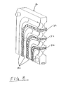
- FIG. 8 is a perspective view of the embodiment of FIG. 1, showing electrical isolation between the cable-receiving passages.
- FIG. 9 is a perspective view of an alternative embodiment (circular) of a modular shielded cable connector.
- FIG. 10 is a perspective view of an alternative embodiment (differential pair) of a modular shielded connector.
- FIG. 11 is an exploded perspective view of an alternate embodiment of the modular shielded connector of FIG. 10 .
- FIG. 12 is a perspective view of an alternative embodiment (using a differential pair) of a modular shielded connector.
- FIG. 13 is an exploded perspective view of an alternate embodiment of the modular shielded connector of FIG. 12 .
- FIG. 1 a first embodiment of a modular shielded coaxial cable connector, generally designated 10 , is shown according to the invention.
- the connector includes at least a pair of plated housing modules, generally designated 12 , defining a plurality of cable-receiving passages, generally designated 14 , therebetween.
- a coaxial cable section, generally designated 16 is disposed in one or more or all of passages 14 . Only one coaxial cable section is shown to avoid cluttering the illustration.
- Enlarged receptacle areas 18 are provided at one or both of the ends of each passage 14 .
- each cable-receiving passage 14 is split axially whereby a passage portion 14 a , 14 b is disposed in each housing module 12 for each passage.
- the passages are split generally along centerlines thereof, whereby passage portions 14 comprise passage-halves 14 a , 14 b which combine to form the whole passages, although non-centerline split passages are possible (not shown).
- the modular shielded coaxial connector may be circular, as illustrated in FIG. 9, with each of the housing modules 12 ′ being generally pie-shaped.
- FIG. 1 shows housing modules 12 separated to better illustrate the opposing passage-halves and the one coaxial cable section 16 . In full assembly, the housing halves are juxtaposed into abutment and held together either by appropriate adhesives or fasteners extending through assembly holes 20 .
- Each coaxial cable section 16 includes a center conductive core 22 surrounded by a dielectric tubular-like sheath 24 .
- the sheath is stripped as shown in FIG. 1, so that a length of core 22 projects into receptacle area 18 of the respective passage 14 .
- An appropriate female connector (not shown) can be inserted into receptacle area 18 .
- each housing module 12 be molded in its desired configuration.
- the housing modules are generally rectangular (square) thin block-like members.
- Passage halves 14 a , 14 b are molded directly into the opposite faces of the housing modules.
- the modules can be molded of appropriate dielectric material such as plastic or the like.
- the entire molded plastic housing modules then are substantially entirely plated with a conductive shielding material.
- the modules can be plated with a conductive metal in a wet chemical electroless process or other suitable process.
- the invention is not limited to the particular configuration of the housing modules shown in FIG. 1 and a wide variety of configurations are readily apparent.
- the invention is not limited to entirely plating the modules, and plating in at least the areas of split passages 14 is contemplated. With the thin modules shown in FIG. 1, and with passage halves 14 a , 14 b being molded on both opposite faces of the modules, plating each entire module has been found to be quite efficient.
- cable-receiving passages 14 formed by passage-halves 14 a , 14 b are generally coplanar and extend at angles through housing modules 12 .
- the passages and passage-halves extend at right-angles and open at adjacent edges of the modules. Therefore, in this embodiment, the passages are split in a plane coextensive with the angle of the passages. In other words, all of the passages between any two adjacent housing modules 12 are in a common plane.
- FIG. 2 shows an alternative embodiment of a connector 10 A wherein the cable-receiving passages extend between a pair of housing modules 12 A at right-angles.
- the passages in connector 10 A are split in a direction generally perpendicular to the planes of the angles of the coaxial cables.
- the housing modules are fabricated the same and like reference numerals have been applied in FIG. 2 corresponding to like components described above in relation to the embodiment of FIG. 1 .
- FIG. 3 simply shows the embodiment of FIG. 1 with a third housing module 12 added.
- This depiction emphasizes that any number of housing modules 12 can be stacked in high density array of coaxial cables 16 , with cable-receiving passages 14 formed by passage-halves 14 a , 14 b being disposed between each adjacent pair of modules in the stacked array thereof.
- electrical isolation 32 exists between the passage halves 14 a , 14 b to provide electrical isolation between the cable-receiving passages.
- the electrical isolation 32 may take the form of selective non-plating of the housing module 12 , although this invention is not limited to only that method of providing electrical isolation between the cable-receiving passages.
- FIGS. 4-7 show the steps in fabricating coaxial cable connector 10 to exemplify the simplicity of the connector as well as the ease in manufacturing and assembling the connector. More particularly, referring first to FIG. 4, a sheet 26 of conductive metal material is provided, and conductors 22 are stamped out of openings 28 in a plurality of groupings lengthwise of the sheet which is provided in strip-like form for feeding through an appropriate stamping machine.
- FIG. 5 shows the next step of overmolding dielectric sheaths 24 about conductive cores 22 . This can be easily accomplished by placing stamped sheet 26 (FIG. 4) into an appropriate molding die and overmolding the dielectric sheaths about the conductive cores, as shown.
- housing modules 12 are molded as plastic blocks including passage halves 14 a , 14 b molded in opposite faces of the blocks, and the plastic blocks then are plated with a conductive shielding material 28 , particularly in the area of the passage halves.
- These molded, plated housing modules can be maintained in inventory and used as needed.
- FIG. 7 shows the next step in fabricating the coaxial cable connector and includes taking the subassembly of FIG. 5 and laying the subassembly onto one or more of the molded and plated housing modules 12 .
- the subassemblies may be fabricated in a continuous fashion so that the subassemblies can be wound onto a reel.
- the subassemblies then can be fed to an indexing machine where they are sequentially laid onto housing modules 12 as the modules are fed seriatim to an assembly station.
- Conductive cores 22 are severed from sheet 26 , as at 30 , either at the point of assembly to the housing modules or thereafter in the assembly line. Holes 20 also can be punched through the housing module at the same time that the cores are severed from the metallic sheet.
- a second housing module 12 can be immediately adhered to or fastened to the assembly shown in FIG. 7 to form a connector as shown at 10 in FIG. 1 .
- coaxial cable sections 16 (FIG. 7) can be adhered within passage halves 14 a , 14 b and a plurality of these assemblies can be stacked, as desired, in a high density array until a housing module such as shown in FIG. 6 is used as an “end cap” at the end of the stacked array.
- FIGS. 10 and 11 illustrate yet another embodiment of a modular shielded connector.
- the connector includes at least a pair of plated housing modules, generally designated 12 , defining a plurality of conductor-receiving passages, generally designated 14 a and 14 b , on either side 12 a , 12 b of the housing modules 12 .
- Conductor-receiving passages 14 a receive one of the conductors 34 that forms the differential signal pair while conductor-receiving passages 14 b receives the other of the conductors 36 that form the differential signal pair.
- Housing modules 12 may also include a tongue 38 on one sidewall 12 a and a groove 40 on the other sidewall 12 b to allow the modular housing modules to be easily aligned with each other to maximize the performance of the differential signal pairs.
- FIGS. 12 and 13 The embodiment illustrated in FIGS. 12 and 13 is similar to that of FIGS. 10 and 11, except that the differential signal pair 42 is not separated into individual conductors 34 , 36 as in FIGS. 10 and 11.
- the differential signal pair 42 is inserted into one of the conductor-receiving passages 14 a , resulting in the differential signal pair 42 extending beyond the sidewall 12 a of the housing module. That portion of the differential signal pair 42 that extends beyond the sidewall 12 a of the housing module is received in the conductor-receiving passage 14 b of the adjacent housing module 12 .
Abstract
Description
Claims (27)
Priority Applications (1)
| Application Number | Priority Date | Filing Date | Title |
|---|---|---|---|
| US10/275,516 US6808414B2 (en) | 2000-05-05 | 2001-05-04 | Modular shielded connector |
Applications Claiming Priority (3)
| Application Number | Priority Date | Filing Date | Title |
|---|---|---|---|
| US09/565,705 US6491545B1 (en) | 2000-05-05 | 2000-05-05 | Modular shielded coaxial cable connector |
| US10/275,516 US6808414B2 (en) | 2000-05-05 | 2001-05-04 | Modular shielded connector |
| PCT/US2001/014512 WO2001086759A2 (en) | 2000-05-05 | 2001-05-04 | Modular shielded connector |
Related Parent Applications (1)
| Application Number | Title | Priority Date | Filing Date |
|---|---|---|---|
| US09/565,705 Continuation-In-Part US6491545B1 (en) | 2000-05-05 | 2000-05-05 | Modular shielded coaxial cable connector |
Publications (2)
| Publication Number | Publication Date |
|---|---|
| US20030203677A1 US20030203677A1 (en) | 2003-10-30 |
| US6808414B2 true US6808414B2 (en) | 2004-10-26 |
Family
ID=24259764
Family Applications (2)
| Application Number | Title | Priority Date | Filing Date |
|---|---|---|---|
| US09/565,705 Expired - Fee Related US6491545B1 (en) | 2000-05-05 | 2000-05-05 | Modular shielded coaxial cable connector |
| US10/275,516 Expired - Fee Related US6808414B2 (en) | 2000-05-05 | 2001-05-04 | Modular shielded connector |
Family Applications Before (1)
| Application Number | Title | Priority Date | Filing Date |
|---|---|---|---|
| US09/565,705 Expired - Fee Related US6491545B1 (en) | 2000-05-05 | 2000-05-05 | Modular shielded coaxial cable connector |
Country Status (6)
| Country | Link |
|---|---|
| US (2) | US6491545B1 (en) |
| JP (1) | JP2003534629A (en) |
| KR (1) | KR100528941B1 (en) |
| CN (1) | CN1200485C (en) |
| AU (1) | AU2001257543A1 (en) |
| WO (1) | WO2001086759A2 (en) |
Cited By (19)
| Publication number | Priority date | Publication date | Assignee | Title |
|---|---|---|---|---|
| US20060172562A1 (en) * | 2005-02-01 | 2006-08-03 | Tyco Electronics Corporation | Electrical connector with contact shielding module |
| US20070155239A1 (en) * | 2004-01-09 | 2007-07-05 | Kouji Nakada | Connector |
| US20080242120A1 (en) * | 2007-03-30 | 2008-10-02 | Intel Corporation | Right-Angle Coaxial Connector |
| US20100144167A1 (en) * | 2008-12-05 | 2010-06-10 | Fedder James L | Electrical Connector System |
| US20100144204A1 (en) * | 2008-12-05 | 2010-06-10 | John Edward Knaub | Electrical connector system |
| US20100151726A1 (en) * | 2008-12-05 | 2010-06-17 | James Lee Fedder | Electrical Connector System |
| US20100151741A1 (en) * | 2008-12-05 | 2010-06-17 | James Lee Fedder | Electrical Connector System |
| US20110028032A1 (en) * | 2009-07-29 | 2011-02-03 | Ubiquiti Networks | Coaxial cable connector system and method |
| US20110237122A1 (en) * | 2008-04-08 | 2011-09-29 | Volker Schwarz | Multiple coaxial connector |
| US8836601B2 (en) | 2013-02-04 | 2014-09-16 | Ubiquiti Networks, Inc. | Dual receiver/transmitter radio devices with choke |
| US8855730B2 (en) | 2013-02-08 | 2014-10-07 | Ubiquiti Networks, Inc. | Transmission and reception of high-speed wireless communication using a stacked array antenna |
| US9172605B2 (en) | 2014-03-07 | 2015-10-27 | Ubiquiti Networks, Inc. | Cloud device identification and authentication |
| US9191037B2 (en) | 2013-10-11 | 2015-11-17 | Ubiquiti Networks, Inc. | Wireless radio system optimization by persistent spectrum analysis |
| US9325516B2 (en) | 2014-03-07 | 2016-04-26 | Ubiquiti Networks, Inc. | Power receptacle wireless access point devices for networked living and work spaces |
| US9368870B2 (en) | 2014-03-17 | 2016-06-14 | Ubiquiti Networks, Inc. | Methods of operating an access point using a plurality of directional beams |
| US9397820B2 (en) | 2013-02-04 | 2016-07-19 | Ubiquiti Networks, Inc. | Agile duplexing wireless radio devices |
| US9496620B2 (en) | 2013-02-04 | 2016-11-15 | Ubiquiti Networks, Inc. | Radio system for long-range high-speed wireless communication |
| US9543635B2 (en) | 2013-02-04 | 2017-01-10 | Ubiquiti Networks, Inc. | Operation of radio devices for long-range high-speed wireless communication |
| US9912034B2 (en) | 2014-04-01 | 2018-03-06 | Ubiquiti Networks, Inc. | Antenna assembly |
Families Citing this family (65)
| Publication number | Priority date | Publication date | Assignee | Title |
|---|---|---|---|---|
| US6491545B1 (en) * | 2000-05-05 | 2002-12-10 | Molex Incorporated | Modular shielded coaxial cable connector |
| US6979202B2 (en) * | 2001-01-12 | 2005-12-27 | Litton Systems, Inc. | High-speed electrical connector |
| US7018239B2 (en) | 2001-01-22 | 2006-03-28 | Molex Incorporated | Shielded electrical connector |
| AU2002306160A1 (en) | 2001-06-13 | 2002-12-23 | Molex Incorporated | High-speed mezzanine connector |
| EP1504502B1 (en) * | 2002-05-06 | 2009-03-18 | Molex Incorporated | Differential signal connectors with esd protection |
| EP1543588A4 (en) * | 2002-07-24 | 2007-04-11 | Winchester Electronics Corp | Interconnection system |
| US6712648B2 (en) * | 2002-07-24 | 2004-03-30 | Litton Systems, Inc. | Laminate electrical interconnect system |
| WO2004077618A2 (en) * | 2003-02-27 | 2004-09-10 | Molex Incorporated | Pseudo-coaxial wafer assembly for connector |
| WO2004084421A2 (en) | 2003-03-14 | 2004-09-30 | Molex Incorporated | Grouped element transmission channel link with pedestal aspects |
| CN1714482A (en) * | 2003-04-24 | 2005-12-28 | 本多通信工业株式会社 | Electric connector and paired contact |
| US6824427B1 (en) * | 2003-05-13 | 2004-11-30 | 3M Innovative Properties Company | Coaxial probe interconnection system |
| US20040242062A1 (en) * | 2003-06-02 | 2004-12-02 | Hughes Karin R. | Methods and apparatus for managing cables and cable connectors |
| WO2005029650A1 (en) * | 2003-09-22 | 2005-03-31 | Honda Tsushin Kogyo Co., Ltd. | Electric connector |
| US6948977B1 (en) * | 2004-08-05 | 2005-09-27 | Bob Behrent | Connector assembly and assembly method |
| US7195519B1 (en) * | 2006-03-30 | 2007-03-27 | Tyco Electronics Corporation | Modular connector assembly with adjustable distance between contact wafers |
| US7288720B1 (en) | 2006-09-19 | 2007-10-30 | Times Microwave Systems, Inc. | Grounding device for bundled cables |
| CN100463309C (en) * | 2006-09-30 | 2009-02-18 | 番禺得意精密电子工业有限公司 | Electric connector and its manufacturing method |
| TW200832449A (en) * | 2006-10-23 | 2008-08-01 | Sumitomo Electric Industries | Coaxial cable and method for manufacturing the same |
| DE112007002801T8 (en) * | 2006-11-24 | 2010-09-30 | AUTONETWORKS Technologies, LTD., Yokkaichi | Shielding conductor and method for producing the shielding conductor |
| US7572147B1 (en) * | 2008-06-27 | 2009-08-11 | Emc Corporation | Line cord filter |
| JP2010033836A (en) * | 2008-07-28 | 2010-02-12 | Fujitsu Ltd | Connector and transmission wire for the connector |
| US7811129B2 (en) * | 2008-12-05 | 2010-10-12 | Tyco Electronics Corporation | Electrical connector system |
| US7871296B2 (en) * | 2008-12-05 | 2011-01-18 | Tyco Electronics Corporation | High-speed backplane electrical connector system |
| US7858882B2 (en) * | 2009-01-23 | 2010-12-28 | Burndy Technology Llc | Connector for core and stranded cable |
| US8366485B2 (en) | 2009-03-19 | 2013-02-05 | Fci Americas Technology Llc | Electrical connector having ribbed ground plate |
| US8006075B2 (en) | 2009-05-21 | 2011-08-23 | Oracle America, Inc. | Dynamically allocated store queue for a multithreaded processor |
| US8231415B2 (en) | 2009-07-10 | 2012-07-31 | Fci Americas Technology Llc | High speed backplane connector with impedance modification and skew correction |
| JP5489691B2 (en) * | 2009-12-16 | 2014-05-14 | 矢崎総業株式会社 | Insulation structure of L-shaped terminal |
| WO2011140438A2 (en) | 2010-05-07 | 2011-11-10 | Amphenol Corporation | High performance cable connector |
| US8187035B2 (en) * | 2010-05-28 | 2012-05-29 | Tyco Electronics Corporation | Connector assembly |
| CN102858143B (en) * | 2011-06-29 | 2016-03-02 | 比亚迪股份有限公司 | A kind of interface shielding sealing device and screening arrangement |
| CH705740B1 (en) * | 2011-11-14 | 2015-08-14 | Huber+Suhner Ag | Cable interface for coaxial cable. |
| EP2624034A1 (en) | 2012-01-31 | 2013-08-07 | Fci | Dismountable optical coupling device |
| CN102544936A (en) * | 2012-02-03 | 2012-07-04 | 西蒙电气(中国)有限公司 | Information module with shielding function in network system |
| CN103296510B (en) * | 2012-02-22 | 2015-11-25 | 富士康(昆山)电脑接插件有限公司 | The manufacture method of terminal module and terminal module |
| USD727852S1 (en) | 2012-04-13 | 2015-04-28 | Fci Americas Technology Llc | Ground shield for a right angle electrical connector |
| USD718253S1 (en) | 2012-04-13 | 2014-11-25 | Fci Americas Technology Llc | Electrical cable connector |
| US9257778B2 (en) | 2012-04-13 | 2016-02-09 | Fci Americas Technology | High speed electrical connector |
| US8944831B2 (en) | 2012-04-13 | 2015-02-03 | Fci Americas Technology Llc | Electrical connector having ribbed ground plate with engagement members |
| USD727268S1 (en) | 2012-04-13 | 2015-04-21 | Fci Americas Technology Llc | Vertical electrical connector |
| US8888519B2 (en) * | 2012-05-31 | 2014-11-18 | Cinch Connectivity Solutions, Inc. | Modular RF connector system |
| US9543703B2 (en) | 2012-07-11 | 2017-01-10 | Fci Americas Technology Llc | Electrical connector with reduced stack height |
| USD751507S1 (en) | 2012-07-11 | 2016-03-15 | Fci Americas Technology Llc | Electrical connector |
| WO2014031851A1 (en) | 2012-08-22 | 2014-02-27 | Amphenol Corporation | High-frequency electrical connector |
| US9093800B2 (en) * | 2012-10-23 | 2015-07-28 | Tyco Electronics Corporation | Leadframe module for an electrical connector |
| US8845366B2 (en) * | 2012-12-17 | 2014-09-30 | Derrick Lewis Brown | Apparatus, system and method for composite and symmetrical hybrid electronic connectors |
| USD745852S1 (en) | 2013-01-25 | 2015-12-22 | Fci Americas Technology Llc | Electrical connector |
| USD720698S1 (en) | 2013-03-15 | 2015-01-06 | Fci Americas Technology Llc | Electrical cable connector |
| US9509101B2 (en) | 2014-01-22 | 2016-11-29 | Amphenol Corporation | High speed, high density electrical connector with shielded signal paths |
| WO2015127196A1 (en) | 2014-02-23 | 2015-08-27 | Cinch Connectivity Solutions, Inc. | High isolation grounding device |
| CN114552261A (en) | 2015-07-07 | 2022-05-27 | 安费诺富加宜(亚洲)私人有限公司 | Electrical connector |
| CN112152020B (en) * | 2015-09-11 | 2022-08-30 | 安费诺富加宜(亚洲)私人有限公司 | Electrical connector having selectively plated plastic components and method of making same |
| KR101851739B1 (en) * | 2015-12-30 | 2018-04-25 | 에이에스텍 주식회사 | Wire harness having screening effect for electromagnetic wave and method for manufacturing the same |
| CN111755867B (en) | 2016-08-23 | 2022-09-20 | 安费诺有限公司 | Configurable high performance connector |
| KR102559377B1 (en) * | 2018-01-22 | 2023-07-26 | 삼성전자주식회사 | Electronic device comprising ac termination and active inductor and interface setting method thereof |
| CN208862209U (en) | 2018-09-26 | 2019-05-14 | 安费诺东亚电子科技(深圳)有限公司 | A kind of connector and its pcb board of application |
| US10939546B2 (en) | 2019-01-28 | 2021-03-02 | Eagle Technology, Llc | Interconnect device |
| EP3703191B1 (en) * | 2019-02-28 | 2022-11-09 | Aptiv Technologies Limited | Electrical connector |
| US11424580B2 (en) * | 2019-06-14 | 2022-08-23 | Sensorview Co., Ltd. | Compact coaxial cable connector for transmitting super high frequency signals |
| JP2021076486A (en) * | 2019-11-11 | 2021-05-20 | 株式会社日本マイクロニクス | Electrical connection device |
| TW202147716A (en) | 2020-01-27 | 2021-12-16 | 美商Fci美國有限責任公司 | High speed, high density direct mate orthogonal connector |
| WO2021154702A1 (en) | 2020-01-27 | 2021-08-05 | Fci Usa Llc | High speed connector |
| US11362456B2 (en) * | 2020-06-30 | 2022-06-14 | Guangzhou Xiongyi Precision Metalworking Co., Ltd. | Wiring arrangement at wall edges and corners with decorative effect |
| CN215816516U (en) | 2020-09-22 | 2022-02-11 | 安费诺商用电子产品(成都)有限公司 | Electrical connector |
| CN213636403U (en) | 2020-09-25 | 2021-07-06 | 安费诺商用电子产品(成都)有限公司 | Electrical connector |
Citations (30)
| Publication number | Priority date | Publication date | Assignee | Title |
|---|---|---|---|---|
| US4921453A (en) | 1989-04-13 | 1990-05-01 | Ici Americas Inc. | Molded complaint springs |
| US4969842A (en) | 1989-11-30 | 1990-11-13 | Amp Incorporated | Molded electrical connector having integral spring contact beams |
| US4969827A (en) | 1989-06-12 | 1990-11-13 | Motorola, Inc. | Modular interconnecting electronic circuit blocks |
| US5028492A (en) | 1990-03-13 | 1991-07-02 | Olin Corporation | Composite coating for electrical connectors |
| US5061198A (en) | 1989-06-15 | 1991-10-29 | Amp Incorporated | Electrical connector system |
| US5066236A (en) * | 1989-10-10 | 1991-11-19 | Amp Incorporated | Impedance matched backplane connector |
| EP0510995A2 (en) | 1991-04-26 | 1992-10-28 | The Whitaker Corporation | Electrical connector having reliable terminals |
| US5167531A (en) * | 1992-03-18 | 1992-12-01 | Amp Incorporated | Stacked electrical connector with diecast housing and drawn shells |
| US5173056A (en) * | 1990-08-30 | 1992-12-22 | Molex Incorporated | Multipole plug-in connector |
| US5281762A (en) * | 1992-06-19 | 1994-01-25 | The Whitaker Corporation | Multi-conductor cable grounding connection and method therefor |
| US5344341A (en) | 1992-03-31 | 1994-09-06 | Nec Corporation | Connector having electromagnetic shielding film |
| US5354219A (en) | 1990-12-21 | 1994-10-11 | Vemako Ab | Multipolar screened connector having a common earth |
| US5387114A (en) * | 1993-07-22 | 1995-02-07 | Molex Incorporated | Electrical connector with means for altering circuit characteristics |
| US5439385A (en) * | 1993-01-14 | 1995-08-08 | Yazaki Corporation | Connector for circuit board |
| EP0693795A1 (en) | 1994-07-22 | 1996-01-24 | Connector Systems Technology N.V. | Selectively metallizized connector with at least one coaxial or twinaxial terminal |
| US5522727A (en) * | 1993-09-17 | 1996-06-04 | Japan Aviation Electronics Industry, Limited | Electrical angle connector of a printed circuit board type having a plurality of connecting conductive strips of a common length |
| US5599595A (en) | 1993-12-09 | 1997-02-04 | Methode Electronics, Inc. | Printed plastic circuits and contacts and method for making same |
| US5626483A (en) | 1994-09-20 | 1997-05-06 | The Whitaker Corporation | Electrical connector having contacts formed by metal plating |
| US5674077A (en) * | 1994-09-30 | 1997-10-07 | Apple Computer, Inc. | Interleaved connector circuit having increased backplane impedance |
| GB2312566A (en) | 1996-04-25 | 1997-10-29 | Motorola Israel Ltd | An adapter |
| US5727956A (en) | 1994-07-22 | 1998-03-17 | Berg Technology, Inc. | Connector assembly including metal strips as contact members |
| US5842872A (en) * | 1995-06-30 | 1998-12-01 | The Whitaker Corporation | Modular right angle board mountable coaxial connector |
| US5943770A (en) * | 1996-04-01 | 1999-08-31 | Framatome Connectors International | Method of making miniature shielded connector with elbow contact shafts |
| US5997358A (en) | 1997-09-02 | 1999-12-07 | Lucent Technologies Inc. | Electrical connector having time-delayed signal compensation |
| US6375512B1 (en) | 1999-10-01 | 2002-04-23 | Motorola, Inc. | Plated plastic connection system and method of making |
| US6491545B1 (en) | 2000-05-05 | 2002-12-10 | Molex Incorporated | Modular shielded coaxial cable connector |
| US6494734B1 (en) * | 1997-09-30 | 2002-12-17 | Fci Americas Technology, Inc. | High density electrical connector assembly |
| US6551140B2 (en) * | 2001-05-09 | 2003-04-22 | Hon Hai Precision Ind. Co., Ltd. | Electrical connector having differential pair terminals with equal length |
| US6702590B2 (en) | 2001-06-13 | 2004-03-09 | Molex Incorporated | High-speed mezzanine connector with conductive housing |
| US6712646B2 (en) * | 2000-10-20 | 2004-03-30 | Japan Aviation Electronics Industry, Limited | High-speed transmission connector with a ground structure having an improved shielding function |
Family Cites Families (4)
| Publication number | Priority date | Publication date | Assignee | Title |
|---|---|---|---|---|
| US5375512A (en) * | 1994-05-31 | 1994-12-27 | Ertmer; Lyle E. | Apparatus to support a fruit or vegetable on a spherical surface and to slice it with a single stroke |
| JP3338976B2 (en) * | 1995-07-27 | 2002-10-28 | モレックス インコーポレーテッド | Connection terminal for electromagnetic shield |
| CA2225151C (en) | 1997-01-07 | 2001-02-27 | Berg Technology, Inc. | Connector with integrated pcb assembly |
| US5980321A (en) * | 1997-02-07 | 1999-11-09 | Teradyne, Inc. | High speed, high density electrical connector |
-
2000
- 2000-05-05 US US09/565,705 patent/US6491545B1/en not_active Expired - Fee Related
-
2001
- 2001-05-04 AU AU2001257543A patent/AU2001257543A1/en not_active Abandoned
- 2001-05-04 KR KR10-2002-7014813A patent/KR100528941B1/en not_active IP Right Cessation
- 2001-05-04 US US10/275,516 patent/US6808414B2/en not_active Expired - Fee Related
- 2001-05-04 WO PCT/US2001/014512 patent/WO2001086759A2/en active IP Right Grant
- 2001-05-04 CN CNB018090575A patent/CN1200485C/en not_active Expired - Fee Related
- 2001-05-04 JP JP2001582873A patent/JP2003534629A/en active Pending
Patent Citations (31)
| Publication number | Priority date | Publication date | Assignee | Title |
|---|---|---|---|---|
| US4921453A (en) | 1989-04-13 | 1990-05-01 | Ici Americas Inc. | Molded complaint springs |
| US4969827A (en) | 1989-06-12 | 1990-11-13 | Motorola, Inc. | Modular interconnecting electronic circuit blocks |
| US5061198A (en) | 1989-06-15 | 1991-10-29 | Amp Incorporated | Electrical connector system |
| US5066236A (en) * | 1989-10-10 | 1991-11-19 | Amp Incorporated | Impedance matched backplane connector |
| US4969842A (en) | 1989-11-30 | 1990-11-13 | Amp Incorporated | Molded electrical connector having integral spring contact beams |
| US5028492A (en) | 1990-03-13 | 1991-07-02 | Olin Corporation | Composite coating for electrical connectors |
| US5173056A (en) * | 1990-08-30 | 1992-12-22 | Molex Incorporated | Multipole plug-in connector |
| US5354219A (en) | 1990-12-21 | 1994-10-11 | Vemako Ab | Multipolar screened connector having a common earth |
| EP0510995A2 (en) | 1991-04-26 | 1992-10-28 | The Whitaker Corporation | Electrical connector having reliable terminals |
| US5167531A (en) * | 1992-03-18 | 1992-12-01 | Amp Incorporated | Stacked electrical connector with diecast housing and drawn shells |
| US5344341A (en) | 1992-03-31 | 1994-09-06 | Nec Corporation | Connector having electromagnetic shielding film |
| US5281762A (en) * | 1992-06-19 | 1994-01-25 | The Whitaker Corporation | Multi-conductor cable grounding connection and method therefor |
| US5439385A (en) * | 1993-01-14 | 1995-08-08 | Yazaki Corporation | Connector for circuit board |
| US5387114A (en) * | 1993-07-22 | 1995-02-07 | Molex Incorporated | Electrical connector with means for altering circuit characteristics |
| US5522727A (en) * | 1993-09-17 | 1996-06-04 | Japan Aviation Electronics Industry, Limited | Electrical angle connector of a printed circuit board type having a plurality of connecting conductive strips of a common length |
| US5688146A (en) | 1993-12-09 | 1997-11-18 | Methode Electronics Inc. | Printed plastic circuits and contracts and method for making same |
| US5599595A (en) | 1993-12-09 | 1997-02-04 | Methode Electronics, Inc. | Printed plastic circuits and contacts and method for making same |
| EP0693795A1 (en) | 1994-07-22 | 1996-01-24 | Connector Systems Technology N.V. | Selectively metallizized connector with at least one coaxial or twinaxial terminal |
| US5727956A (en) | 1994-07-22 | 1998-03-17 | Berg Technology, Inc. | Connector assembly including metal strips as contact members |
| US5626483A (en) | 1994-09-20 | 1997-05-06 | The Whitaker Corporation | Electrical connector having contacts formed by metal plating |
| US5674077A (en) * | 1994-09-30 | 1997-10-07 | Apple Computer, Inc. | Interleaved connector circuit having increased backplane impedance |
| US5842872A (en) * | 1995-06-30 | 1998-12-01 | The Whitaker Corporation | Modular right angle board mountable coaxial connector |
| US5943770A (en) * | 1996-04-01 | 1999-08-31 | Framatome Connectors International | Method of making miniature shielded connector with elbow contact shafts |
| GB2312566A (en) | 1996-04-25 | 1997-10-29 | Motorola Israel Ltd | An adapter |
| US5997358A (en) | 1997-09-02 | 1999-12-07 | Lucent Technologies Inc. | Electrical connector having time-delayed signal compensation |
| US6494734B1 (en) * | 1997-09-30 | 2002-12-17 | Fci Americas Technology, Inc. | High density electrical connector assembly |
| US6375512B1 (en) | 1999-10-01 | 2002-04-23 | Motorola, Inc. | Plated plastic connection system and method of making |
| US6491545B1 (en) | 2000-05-05 | 2002-12-10 | Molex Incorporated | Modular shielded coaxial cable connector |
| US6712646B2 (en) * | 2000-10-20 | 2004-03-30 | Japan Aviation Electronics Industry, Limited | High-speed transmission connector with a ground structure having an improved shielding function |
| US6551140B2 (en) * | 2001-05-09 | 2003-04-22 | Hon Hai Precision Ind. Co., Ltd. | Electrical connector having differential pair terminals with equal length |
| US6702590B2 (en) | 2001-06-13 | 2004-03-09 | Molex Incorporated | High-speed mezzanine connector with conductive housing |
Cited By (35)
| Publication number | Priority date | Publication date | Assignee | Title |
|---|---|---|---|---|
| US20070155239A1 (en) * | 2004-01-09 | 2007-07-05 | Kouji Nakada | Connector |
| US7381092B2 (en) | 2004-01-09 | 2008-06-03 | Japan Aviation Electronics Industry, Limited | Connector |
| US7118381B2 (en) * | 2005-02-01 | 2006-10-10 | Tyco Electronics Corporation | Electrical connector with contact shielding module |
| US20060172562A1 (en) * | 2005-02-01 | 2006-08-03 | Tyco Electronics Corporation | Electrical connector with contact shielding module |
| US20080242120A1 (en) * | 2007-03-30 | 2008-10-02 | Intel Corporation | Right-Angle Coaxial Connector |
| US7473137B2 (en) * | 2007-03-30 | 2009-01-06 | Intel Corporation | Right-angle coaxial connector |
| US20110237122A1 (en) * | 2008-04-08 | 2011-09-29 | Volker Schwarz | Multiple coaxial connector |
| US8360805B2 (en) * | 2008-04-08 | 2013-01-29 | Huber + Suhner Ag | Connector banks arranged in parallel and floating manner |
| US8187034B2 (en) * | 2008-12-05 | 2012-05-29 | Tyco Electronics Corporation | Electrical connector system |
| US20100151741A1 (en) * | 2008-12-05 | 2010-06-17 | James Lee Fedder | Electrical Connector System |
| US7931500B2 (en) * | 2008-12-05 | 2011-04-26 | Tyco Electronics Corporation | Electrical connector system |
| US7976318B2 (en) * | 2008-12-05 | 2011-07-12 | Tyco Electronics Corporation | Electrical connector system |
| US20100151726A1 (en) * | 2008-12-05 | 2010-06-17 | James Lee Fedder | Electrical Connector System |
| US8157591B2 (en) * | 2008-12-05 | 2012-04-17 | Tyco Electronics Corporation | Electrical connector system |
| US20100144204A1 (en) * | 2008-12-05 | 2010-06-10 | John Edward Knaub | Electrical connector system |
| US20100144167A1 (en) * | 2008-12-05 | 2010-06-10 | Fedder James L | Electrical Connector System |
| US20110028032A1 (en) * | 2009-07-29 | 2011-02-03 | Ubiquiti Networks | Coaxial cable connector system and method |
| US7934952B2 (en) * | 2009-07-29 | 2011-05-03 | Ubiquiti Networks | Coaxial cable connector system and method |
| US9490533B2 (en) | 2013-02-04 | 2016-11-08 | Ubiquiti Networks, Inc. | Dual receiver/transmitter radio devices with choke |
| US9496620B2 (en) | 2013-02-04 | 2016-11-15 | Ubiquiti Networks, Inc. | Radio system for long-range high-speed wireless communication |
| US9543635B2 (en) | 2013-02-04 | 2017-01-10 | Ubiquiti Networks, Inc. | Operation of radio devices for long-range high-speed wireless communication |
| US9397820B2 (en) | 2013-02-04 | 2016-07-19 | Ubiquiti Networks, Inc. | Agile duplexing wireless radio devices |
| US8836601B2 (en) | 2013-02-04 | 2014-09-16 | Ubiquiti Networks, Inc. | Dual receiver/transmitter radio devices with choke |
| US9293817B2 (en) | 2013-02-08 | 2016-03-22 | Ubiquiti Networks, Inc. | Stacked array antennas for high-speed wireless communication |
| US8855730B2 (en) | 2013-02-08 | 2014-10-07 | Ubiquiti Networks, Inc. | Transmission and reception of high-speed wireless communication using a stacked array antenna |
| US9531067B2 (en) | 2013-02-08 | 2016-12-27 | Ubiquiti Networks, Inc. | Adjustable-tilt housing with flattened dome shape, array antenna, and bracket mount |
| US9373885B2 (en) | 2013-02-08 | 2016-06-21 | Ubiquiti Networks, Inc. | Radio system for high-speed wireless communication |
| US9191037B2 (en) | 2013-10-11 | 2015-11-17 | Ubiquiti Networks, Inc. | Wireless radio system optimization by persistent spectrum analysis |
| US9325516B2 (en) | 2014-03-07 | 2016-04-26 | Ubiquiti Networks, Inc. | Power receptacle wireless access point devices for networked living and work spaces |
| US9172605B2 (en) | 2014-03-07 | 2015-10-27 | Ubiquiti Networks, Inc. | Cloud device identification and authentication |
| US9368870B2 (en) | 2014-03-17 | 2016-06-14 | Ubiquiti Networks, Inc. | Methods of operating an access point using a plurality of directional beams |
| US9843096B2 (en) | 2014-03-17 | 2017-12-12 | Ubiquiti Networks, Inc. | Compact radio frequency lenses |
| US9912053B2 (en) | 2014-03-17 | 2018-03-06 | Ubiquiti Networks, Inc. | Array antennas having a plurality of directional beams |
| US9912034B2 (en) | 2014-04-01 | 2018-03-06 | Ubiquiti Networks, Inc. | Antenna assembly |
| US9941570B2 (en) | 2014-04-01 | 2018-04-10 | Ubiquiti Networks, Inc. | Compact radio frequency antenna apparatuses |
Also Published As
| Publication number | Publication date |
|---|---|
| US20030203677A1 (en) | 2003-10-30 |
| WO2001086759A3 (en) | 2002-04-04 |
| WO2001086759A2 (en) | 2001-11-15 |
| CN1436381A (en) | 2003-08-13 |
| US6491545B1 (en) | 2002-12-10 |
| CN1200485C (en) | 2005-05-04 |
| KR20030017509A (en) | 2003-03-03 |
| AU2001257543A1 (en) | 2001-11-20 |
| JP2003534629A (en) | 2003-11-18 |
| KR100528941B1 (en) | 2005-11-23 |
Similar Documents
| Publication | Publication Date | Title |
|---|---|---|
| US6808414B2 (en) | Modular shielded connector | |
| US6926553B2 (en) | Cable assembly with improved grounding means | |
| US6939174B2 (en) | Cable assembly with internal circuit modules | |
| US6739910B1 (en) | Cable assembly with internal circuit modules | |
| US7147512B2 (en) | Connector assembly | |
| US7316584B2 (en) | Matched impedance shielded pair interconnection system for high reliability applications | |
| US6699072B1 (en) | Cable assembly | |
| US6857912B2 (en) | Cable assembly with internal circuit modules | |
| US9991639B2 (en) | Wafer connector with grounding clamp | |
| US20020022401A1 (en) | High speed connector | |
| US6837741B2 (en) | Connector and cable positioning member of connector | |
| EP0517180A1 (en) | Electrical connectors | |
| EP0840406A2 (en) | Modular plug and modular jack | |
| JP2704305B2 (en) | High frequency connector and method of manufacturing the same | |
| US6814620B1 (en) | Electrical connector | |
| US4707040A (en) | Connector for coaxially shielded cable | |
| US6293829B1 (en) | Electrical connector with wire management system | |
| US20020125967A1 (en) | Air dielectric backplane interconnection system | |
| US20030176085A1 (en) | Electrical connector assembly | |
| US6283792B1 (en) | Extruded metallic electrical connector assembly and method of producing same | |
| JP2001015187A (en) | Coaxial cable connector | |
| EP0951092A2 (en) | Electrical connector for coaxial cables | |
| EP0131248B1 (en) | Connector for coaxially shielded cable | |
| JPH06208858A (en) | Coaxial cable connecting device | |
| JP2007534110A (en) | Connector shell for multi-wire cable assembly |
Legal Events
| Date | Code | Title | Description |
|---|---|---|---|
| AS | Assignment |
Owner name: MOLEX INCORPORATED, ILLINOIS Free format text: ASSIGNMENT OF ASSIGNORS INTEREST;ASSIGNORS:SPIEGEL, MARKO;DUNHAM, DAVID E.;ZADEREJ, VICTOR;REEL/FRAME:015639/0316 Effective date: 20040729 |
|
| FPAY | Fee payment |
Year of fee payment: 4 |
|
| REMI | Maintenance fee reminder mailed | ||
| AS | Assignment |
Owner name: UNIVERSITE LAVAL, CANADA Free format text: ASSIGNMENT OF ASSIGNORS INTEREST;ASSIGNORS:ALLEN, CHRISTINE;PAQUET, ALEX;CHARLEBOIS, MAXIME;REEL/FRAME:026426/0380 Effective date: 20100707 |
|
| REMI | Maintenance fee reminder mailed | ||
| LAPS | Lapse for failure to pay maintenance fees | ||
| STCH | Information on status: patent discontinuation |
Free format text: PATENT EXPIRED DUE TO NONPAYMENT OF MAINTENANCE FEES UNDER 37 CFR 1.362 |
|
| FP | Lapsed due to failure to pay maintenance fee |
Effective date: 20121026 |