US7459907B2 - Flow measurement using NMR - Google Patents
Flow measurement using NMR Download PDFInfo
- Publication number
- US7459907B2 US7459907B2 US11/676,737 US67673707A US7459907B2 US 7459907 B2 US7459907 B2 US 7459907B2 US 67673707 A US67673707 A US 67673707A US 7459907 B2 US7459907 B2 US 7459907B2
- Authority
- US
- United States
- Prior art keywords
- magnetic field
- gradient
- fluid
- velocity
- nmr
- Prior art date
- Legal status (The legal status is an assumption and is not a legal conclusion. Google has not performed a legal analysis and makes no representation as to the accuracy of the status listed.)
- Active
Links
Images


Classifications
-
- G—PHYSICS
- G01—MEASURING; TESTING
- G01R—MEASURING ELECTRIC VARIABLES; MEASURING MAGNETIC VARIABLES
- G01R33/00—Arrangements or instruments for measuring magnetic variables
- G01R33/20—Arrangements or instruments for measuring magnetic variables involving magnetic resonance
- G01R33/44—Arrangements or instruments for measuring magnetic variables involving magnetic resonance using nuclear magnetic resonance [NMR]
- G01R33/48—NMR imaging systems
- G01R33/54—Signal processing systems, e.g. using pulse sequences ; Generation or control of pulse sequences; Operator console
- G01R33/56—Image enhancement or correction, e.g. subtraction or averaging techniques, e.g. improvement of signal-to-noise ratio and resolution
- G01R33/561—Image enhancement or correction, e.g. subtraction or averaging techniques, e.g. improvement of signal-to-noise ratio and resolution by reduction of the scanning time, i.e. fast acquiring systems, e.g. using echo-planar pulse sequences
- G01R33/5613—Generating steady state signals, e.g. low flip angle sequences [FLASH]
-
- G—PHYSICS
- G01—MEASURING; TESTING
- G01N—INVESTIGATING OR ANALYSING MATERIALS BY DETERMINING THEIR CHEMICAL OR PHYSICAL PROPERTIES
- G01N24/00—Investigating or analyzing materials by the use of nuclear magnetic resonance, electron paramagnetic resonance or other spin effects
- G01N24/08—Investigating or analyzing materials by the use of nuclear magnetic resonance, electron paramagnetic resonance or other spin effects by using nuclear magnetic resonance
- G01N24/081—Making measurements of geologic samples, e.g. measurements of moisture, pH, porosity, permeability, tortuosity or viscosity
-
- G—PHYSICS
- G01—MEASURING; TESTING
- G01R—MEASURING ELECTRIC VARIABLES; MEASURING MAGNETIC VARIABLES
- G01R33/00—Arrangements or instruments for measuring magnetic variables
- G01R33/20—Arrangements or instruments for measuring magnetic variables involving magnetic resonance
- G01R33/44—Arrangements or instruments for measuring magnetic variables involving magnetic resonance using nuclear magnetic resonance [NMR]
- G01R33/48—NMR imaging systems
- G01R33/54—Signal processing systems, e.g. using pulse sequences ; Generation or control of pulse sequences; Operator console
- G01R33/56—Image enhancement or correction, e.g. subtraction or averaging techniques, e.g. improvement of signal-to-noise ratio and resolution
- G01R33/563—Image enhancement or correction, e.g. subtraction or averaging techniques, e.g. improvement of signal-to-noise ratio and resolution of moving material, e.g. flow contrast angiography
- G01R33/56308—Characterization of motion or flow; Dynamic imaging
Definitions
- the invention relates generally to flow measurement methods and systems.
- embodiments relate to flow measurements using Nuclear Magnetic Resonance (NMR) instruments.
- NMR Nuclear Magnetic Resonance
- Non-invasive (low measurements such as ultrasonic meters and NMR sensors have certain advantages over conventional flow meters. These advantages include: excellent long-term repeatability, less sensitivity to fluid properties such as viscosity and pressure, higher accuracy, wider range of linearity, and lower cost of maintenance due to the lack of moving parts. Thus, non-invasive flow measurements are particularly well-suited for downhole tools in the oil and gas industry.
- U.S. Pat. No. 6,046,587 issued to King et al. discloses methods and apparatus for measuring flow velocity of multiphase fluids flowing in a pipeline.
- the King et al. patent teaches using the ratio of FID amplitudes of signals acquired with different delay times to infer flow velocity using a single NMR sensor.
- the FID signal is difficult to measure using permanent magnets because static magnetic field variations will result in signals that decay too fast for reliable detection.
- the King et al. methods for determining flow velocity do not account for the fact that there is a distribution of (low velocity in a pipe.
- the King et al. apparatus consists of two separated NMR sensors. The flow-velocity and fluid volumes for multiphase fluid flow are computed from FID measurements from the two sensors. However, the computation requires prior knowledge of the fluid T 1 distributions.
- a magnetic field gradient needs to be used across a sample to be measured, resulting in a variation of frequency ⁇ a over the sample.
- the magnetic field gradient can also be used to measure flow properties.
- the magnetic field gradient causes a periodicity in spin density in the sample.
- a typical sequence used in various applications is referred to as a spin-echo sequence, including a 90° pulse, which rotates the net magnetization from the X direction down to the Y-Z plane, followed by a 180° pulse, which rotates the magnetization by 180° about the Y axis.
- the 180° pulse re-phases the magnetization thus producing a signal, i.e., the spin-echo signal.
- an RF pulse can cause spin excitations in a fluid, and if the fluid is flowing, a group of nuclei in excited state is carried by the flow.
- An echo signal in a time axis carries information on the flow properties such as the flow velocity.
- reservoir fluid properties can be measured using an NMR module in a downhole tool, such as the fluid sampling tool disclosed in U.S. Pat. No. 6,346,813 B1 issued to Kleinberg.
- An example of formation fluid tester tool is the Modular Formation Dynamics Testing tool marketed under the trade name of MDTTM by Schlumberger Technology Corp. (Houston, Tex.).
- FIG. 1 shows an exemplary formation fluid testing tool body 10 (e.g., an MDTTM tool) that houses the following modules: an electric power module 11 ; a hydraulic power module 12 ; a probe module 13 , which may be deployed to make a hydraulic seal with the formation; an optical fluid analyzer module 14 ; an NMR module 15 , a multi-sample module 16 , and a pumpout module 17 .
- the tool body 10 may enclose a processor and a memory for downhole data collection and processing.
- the tool body 10 is designed to work in harsh downhole environments.
- the NMR module 15 may include an NMR sensor, which includes a magnet that can produce a substantially homogeneous static magnetic field over the volume of the fluid sample.
- the NMR sensor includes at least one coil that can produce pulsed field gradients (PFG) of defined amplitudes and time durations across the sample volume.
- PFG pulsed field gradients
- a homogeneous static magnetic field in combination with a PFG can provide measurements with better signal-to-noise ratios because a larger sample volume is resonated, as compared to a static magnetic field having a static field gradient, which can only excite a small portion of the sample (a “sample slice”) to resonate.
- the NMR sensor also includes a coil (an RF antenna) for producing RF pulses. The magnetic moment of the RF antenna is substantially perpendicular to the magnetic moment of the static magnetic field.
- the NMR sensor includes some basic elements such as a magnet to generate a substantially homogeneous “base” field and RF antenna to excite a portion of the flow.
- FIG. 2A shows an illustration of an NMR sensor 20 disclosed by Freedman in U.S. Pat. No. 6,952,096, for determining flow velocity and other properties of a fluid flowing in a flowline (or flow pipe) 22 .
- a magnet 24 and an RF antenna 26 are included in the NMR sensor 20 .
- the flowline 22 includes a pre-polarization section 28 that is upstream of an investigation section 29 .
- the magnet 24 is disposed around both the pre-polarization section 28 and the investigation section 29 .
- the magnet 24 may be a permanent magnet or an electromagnet.
- the flowline 22 is typically made of a non-conductive and non-magnetic material, such as a composite or polymer material. However, if the flowline 22 is made of a conductive or magnetic material (e.g., steel), then the antenna 26 should be located inside the flowline.
- the antenna (solenoid coil) 26 functions as both a transmitter and a receiver.
- the RF antenna emits RF electromagnetic pulses along the direction of the RF antenna.
- the RF antenna 26 substantially covers the investigation section 29 of the flowline 22 .
- W variable wait time
- the amplitudes of the detected spin-echo signals for the different wait times depend on flow velocity, wait time, receiver and transmitter antenna lengths, magnet pre-polarization length, and the T 1 distribution of the fluid. All of these parameters, except the flow velocity and the T 1 distribution of the fluid, are either fixed by the sensor design or by the pulse sequence. If sufficient sets of measurements are available, these parameters may be derived by fitting the measured signals to a proper model that simulates the NMR response of the flowing fluid. That is, the data may be interpreted by forward modeling.
- a theoretical forward model can be used to simulate the echo signals for any combination of the aforementioned pulse sequence, sensor parameters, flow velocity, and T 1 distribution.
- the forward model may be used iteratively in an inversion to determine the apparent flow velocity and T 1 distribution.
- the forward model can be lit by inversion to determine the T 1 distribution.
- FIG. 2B shows that the velocity- and position-dependent polarization profile f(v,z) over the length l a of the receiver coil (shown as 26 in FIG. 2A ) is made of two parts.
- the first part comes from fresh spins that are “pre-polarized” as they travel in the static magnetic field into the receiver during the wait time W.
- the second part comes from spins that were in the receiver coil and are “re-polarized” during the wait time.
- the pre-polarization length l p shown in FIGS. 2A and 2B corresponds to the length of the pre-polarization region 28 .
- T(z, v) 1 - exp ( - T ⁇ ( z , v ) T 1 ) , ( 1 )
- T(z, v) is the polarization time for a spin with position z and velocity v
- T 1 is the longitudinal relaxation time of the spins.
- the polarization time, T(z,v) is defined as:
- FIG. 3A shows a suite of VWT pulses consisting of N measurements. N is typically on the order of 10. At the conclusion of each measurement in the suite, one or more spoiling pulses (collectively denoted by the pulse S) are applied to destroy any remnant magnetization before starting the wait lime for the next measurement. The duration and frequencies of the spoiling pulses are instrument dependent and can be determined empirically.
- a 90° excitation pulse is applied to rotate the longitudinal magnetization into the transverse plane.
- the signal from the transverse magnetization rapidly de-phases due to inhomogeneity (or other factors) in the static magnetic field, but is refocused by the 180° pulse to produce a spin-echo signal.
- a spoiling pulse is applied to remove the magnetization of the spins within the receiver coil.
- Other VWT sequences similar to the one shown in FIGS. 3A and 3B can also be used to observe FID signals instead of a spin-echo signal.
- Both the inversion-recovery and the saturation-recovery pulse sequences are generally referred to as “T 1 -relaxation investigation pulse sequences.”
- the pulse sequence used to acquire the NMR signals are generally referred to as an “acquisition pulse sequence.”
- An acquisition pulse sequence may include a single 90° pulse, a spin-echo pulse (i.e., a 90° pulse followed by a 180° pulse), and the variants of the spin-echo pulse such as the Carr-Purcell-Meiboom-Gill (CPMG) sequence, i.e., multiple 180°, refocusing pulses following a single 90° excitation pulse.
- CPMG Carr-Purcell-Meiboom-Gill
- the “variable wait time pulse sequence” as shown in FIGS. 3A and 3B comprises a spoiling pulse, a wait time, and an acquisition pulse sequence.
- the spin-echo pulse sequence and its variants are generally referred to as a “spin-echo pulse sequence.” That is, a “spin-echo pulse sequence” not only includes a single 90° pulse and a single 180° pulse, but also may include multiple 180° pulses after the 90° pulse.
- Equation (2a) shows that in the region. 0 ⁇ z ⁇ vW, fresh spins have entered the antenna during the wait time. The length of this region depends on v and W. The polarization time for these fresh spins is independent of W. Instead, it depends on the duration that the spins have been exposed to the static magnetic field since they entered the field of the permanent magnet. This is because this portion of the fluid is outside the transmitter/receiver antenna (shown as 26 in FIG. 2A ) when the spoiling pulse is applied and the magnetizations of the spins in this portion of the fluid are not “killed” by the spoiling pulse. On the other hand, as can be seen from Eq.
- the re-polarization of the spins in the adjoining region of length is controlled by W because these spins were in the transmitter/receiver region when the spoiling pulse was applied.
- the magnetizations of these spins were removed by the spoiling pulse, and any polarization detected by the receiver is due to re-polarization during W. If W is long or v is fast enough such that v ⁇ W exceeds the antenna length, then only fresh spins (those that enter the receiver antenna after the spoiling pulse) are measured and the polarization function is independent of W.
- Madio et al. show a linear relationship between the phase difference of odd and even echoes and the product of the flow velocity and the static magnetic field gradient, up to a flow velocity of 6 cm/sec. At higher flow velocities, the phase difference is no longer an adequate velocity indicator.
- Forward models can be used to predict the NMR sensor signals, which depends on the flow velocity, the distribution of T 1 , the wait time, and geometrical parameters such as the antenna length, the magnet pre-polarization length, and the radius of the flowline.
- the only variables in the forward model are the flow velocity and the T 1 distribution of the fluid.
- the flow velocity and T 1 distribution are determined by inversion.
- the forward model is derived in the following paragraphs.
- FIG. 4 shows the velocity profiles for laminar flow and non-laminar flow in a circular pipe.
- v ⁇ ( r ) - ( r 2 - r 0 2 ) r 0 2 ⁇ ⁇ v m ( 4 ⁇ a )
- v ⁇ ( r ) v m ⁇ ( 1 - r r 0 ) 1 / n ( 4 ⁇ b ) where n is typically between 5 and 10.
- FIG. 5 illustrates a spin-echo pulse sequence that can be used to measure a flow velocity, as disclosed by Carr and Purcell (the Physical Review, v. 94, no. 3, pp. 630-638, 1954).
- the ratio of even to odd spin echo amplitude e.g., the ratio between the amplitudes of the even spin-echo signal 52 and the odd spin-echo signal 51 ′ is proportional to the flow velocity.
- the flow velocity can be derived.
- a nuclear magnetic resonance (NMR) tool and method are used to determine a velocity distribution or velocity image of a flowing fluid in a downhole environment.
- the method comprises applying a radio frequency pulse sequence; applying a magnetic field gradient pulse sequence, wherein each magnetic field gradient pulse has parameters including a gradient magnetic field and a gradient pulse duration; measuring a NMR signal; determining a phase characteristic of the NMR signal: and determining the velocity distribution or image of the fluid using the determined phase characteristic, the magnetic field gradient pulse parameters, and a time delay between gradient pulses.
- Embodiments disclosed herein relate to a downhole system to determine a flow property of a formation fluid flowing in a flowline, comprising a formation fluid testing tool and a nuclear magnetic resonance tool.
- FIG. 1 Another embodiments disclosed herein related to a method to determine the magnitude of a gradient magnetic field using a nuclear magnetic resonance tool disposed in a wellbore, comprising applying a radio frequency pulse sequence; applying a magnetic field gradient pulse sequence, wherein each magnetic field gradient pulse has parameters including a gradient magnetic field and a gradient pulse duration; measuring a NMR signal in the presence of a gradient pulse; determining a frequency spread from the NMR signal; and determining the magnitude of the gradient magnetic field using the frequency spread.
- FIG. 1 shows a prior art formation fluid testing tool including an NMR module.
- FIG. 2A shows a schematic of a prior art NMR sensor.
- FIG. 2B shows a spin-polarization profile along a flowline in the NMR sensor of FIG. 2A .
- FIG. 3A illustrates a pulse sequence for acquiring VWT NMR measurements.
- FIG. 3B illustrates a pulse sequence including a spoiling pulse.
- FIG. 4 illustrates a laminar flow and a non-laminar flow, respectively.
- FIG. 5 shows a pulse sequence and corresponding spin-echo signal amplitudes for a flow velocity measurement in the prior art.
- FIG. 6 shows an NMR sensor having a magnetic field gradient orthogonal to a flowline direction in accordance with an embodiment of the invention.
- FIG. 7 shows an NMR sensor having a magnetic field gradient along a flowline direction in accordance with an embodiment of the invention.
- FIG. 8 shows a pulse sequence for generating a phase shift for flowing spins in a spin-echo signal in accordance with an embodiment of the invention.
- FIG. 9 shows a linear fit to phase data used to derive a velocity for a flow rate of about 200 cc/min.
- FIG. 10 shows a linear fit to phase data used to derive a velocity for a flow rate of about 300 cc/min.
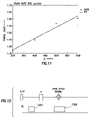
- FIG. 11 shows a linear fit to phase data used to derive a velocity for a flow rate of about 500 cc/min.
- FIG. 12 shows a pulse sequence for generating a frequency-encoded spin-echo signal used in measuring an amplitude of a magnetic field gradient in accordance with an embodiment of the invention.
- FIG. 13 shows a Fourier Transform of the frequency-encoded spin-echo signal.
- FIG. 14 shows a pulse sequence used in obtaining a velocity profile by varying a time duration of the magnetic field gradient.
- FIG. 15 shows a pulse sequence used in obtaining a velocity profile by varying an amplitude of the magnetic field gradient.
- FIG. 16 shows a pulse sequence for velocity field imaging, including a velocity-encoded pulse, a phase-encoded pulse, and a frequency-encoded pulse.
- FIG. 17 shows an NMR sensor for imaging a velocity profile in accordance with an embodiment of die invention.
- FIG. 18 is a flowchart showing a method of measuring a flow velocity in accordance with an embodiment of the invention
- Embodiments of the invention relate to a method and apparatus for measuring flow properties, particularly a flow velocity, based on measuring a phase of an NMR signal.
- a magnetic field gradient pulse is used to shift the phase of the NMR signal.
- U.S. Pat. No. 7,053,611 issued to Freedman on May 30, 2006, and assigned to the assignee of the present invention, has disclosed an NMR sensor that includes means for generating a pulsed magnetic field gradient (PFG).
- PFG pulsed magnetic field gradient
- This NMR sensor exploits NMR signal amplitude information, but not phase information.
- the structure of the NMR sensor and pulse sequences disclosed by Freedman in the 611 patent is described in the following paragraphs with reference to FIG. 6 to facilitate the understanding of a basic NMR sensor structure, and particularly the means for generating a pulsed magnetic field gradient.
- the NMR sensor 60 includes a magnet 61 designed to produce a substantially homogeneous magnetic field (B 0 ) in a sample volume 62 .
- the magnet 61 may be a permanent magnet made of Samarium Cobalt or any other suitable material.
- the magnet 61 may be an electromagnet.
- the magnet 61 which may comprise a single piece or several pieces that surround the sample volume 62 , may further include permeable pole pieces attached to its surfaces for shaping the magnetic field and for reducing the magnetic field gradient in the sample region so that B 0 is substantially homogeneous over the sample volume 62 .
- the sample volume 62 is configured to be connected to a formation fluid flowline so that the sensor 60 can be used to measure or monitor the properties of the fluid flowing through the flowline.
- An RF antenna (coil) 63 surrounds the sample volume 62 .
- the RF antenna 63 is designed to radiate an oscillating RF magnetic field (B 1 ), i.e., an RF pulse, having a magnetic moment substantially perpendicular (orthogonal) to that of the static magnetic field B 0 produced by the magnet 61 .
- the RF antenna 63 may comprise a solenoid coil, a saddle coil, or any other suitable coil.
- the same RF antenna 63 may function as a transmitter to transmit the oscillating magnetic field, and as a receiver to receive the signals. Alternatively, separate transmitter and receiving antennas may be used.
- the NMR sensor 60 shown in FIG. 6 also includes two gradient coils 65 a and 65 b that are configured to produce a magnetic field gradient across the volume of the sample 62 .
- the gradient coils 65 a and 65 b produce a linear gradient along the direction of the flowline.
- the gradient coils 65 a and 65 b are connected to a control unit 67 that can energize the gradient coils 65 a and 65 b at a selected amplitude for a predetermined time duration. While two gradient coils 65 a and 65 b are shown, one of ordinary skill in the art would appreciate that one or more gradient coils may be used.
- opposing magnetic fields b g may be created to induce a magnetic field gradient g over the sample volume.
- the magnitude of the magnetic field gradient g is usually measured in units of Gauss/cm.
- the sensor 60 may be protected and supported by a housing 64 .
- the housing 64 may be made of a magnetic steel with high magnetic permeability for confining the magnetic field B 0 and for providing strength to the assembly.
- a shield 66 may be included for separating the RF antenna 63 and the magnet 61 .
- the shield may be made of a material (e.g., copper) that can prevent the oscillating RF magnetic field produced by the RF antenna 63 from interacting with the magnet 61 so that magneto-acoustic ringing in the magnet can be minimized.
- the NMR sensor 60 can be used for measurements related to the diffusion and relaxation properties of fluid samples. Because these properties are generally different for oil and water, these measurements can provide means for determining the relative proportion of water and oil in a fluid sample. In addition, these measurements can provide information on oil properties such as composition, viscosity, and gas/oil ratio (amount of dissolved gas contained in the oil). Similarly, for a fluid sample, which may comprises (1) gas and water, (2) gas, oil, and water, (3) oil and gas, or (4) oil and water, the measurements can provide a means for determining the relative proportions of the different components. In addition, these measurements can provide information on the hydrocarbon properties that are important for determining the economic value of the reservoir that are essential for making well completion decisions.
- Embodiments of the present invention exploit information carried by the phases of spin-echo signals.
- a magnetic field gradient pulse is used to shift die phase of the spin-echo signals.
- An NMR sensor 80 is shown in FIG. 7 . Similar to the NMR sensor 60 of FIG. 6 , the sensor 80 also includes a magnet 81 designed to produce a substantially homogeneous magnetic field (B 0 ) in a sample volume 82 .
- An RF antenna (coil) 83 surrounds the sample volume 82 .
- the RF antenna 83 is designed to radiate an oscillating RF magnetic field (B 1 ), i.e.,. an RF pulse, having a magnetic moment substantially perpendicular (orthogonal) to that of the static magnetic field B 0 produced by the magnet 81 .
- the RF antenna 83 may comprise a solenoid coil, a saddle coil, or any other suitable coil.
- the same RF antenna 83 may function as a transmitter to transmit the oscillating magnetic field arid as a receiver to receive the signals. Alternatively, separate transmitter and receiving antennas may be used.
- the NMR sensor 80 shown in FIG. 7 also includes two gradient coils 85 a and 85 b that are configured to produce a magnetic field gradient across the sample volume 82 substantially along the flowline.
- the gradient coils 85 a and 85 b are connected to a control unit 87 that can energize the gradient coils 85 a and 85 b at a selected amplitude for a predetermined time duration. While two gradient coils 85 a and 85 b are shown in the exemplary configuration, one of ordinary skill in the art would appreciate that using just one gradient coil may be sufficient. Alternatively, more than two gradient coils may be used. In addition, the orientation of the gradient coils may be different from that shown in FIG. 7 .
- a spin-echo signal would have a shifted phase that can be exploited for measuring a flow velocity as discussed below.
- the NMR sensor 80 may further include a phase measuring unit 88 and a calculation unit 89 .
- the phase measuring unit 88 is used to measure the phases of the signals received by the RF antenna 83 .
- the calculation unit 89 then uses the measured signal phases 10 derive a flow velocity.
- the phase measuring unit 88 and the calculation unit 89 may be embodied within the downhole tool 10 shown in FIG. 1 Alternatively, the data can be sent to the surface via an uphole data link and analyzed at the surface.
- the sensor 80 may be protected and supported by a housing (not shown) and may include a shield (not shown) similar to those in FIG. 6 .
- a PFG spin-echo sequence in accordance with an embodiment of the invention is shown in FIG. 8 .
- a first magnetic field gradient pulse G Z which is along the Z-axis, i.e., the flowline direction, is applied between the 90° RF tipping pulse and the 180° RF re-focusing pulse.
- a second magnetic field gradient pulse of the same amplitude and the same time duration is applied alter the 180° RF pulse, but before the spin-echo is formed.
- the field gradient pulse G Z causes a measurable phase shift in the spin-echo signal.
- the phase accumulation of spins can be calculated using ⁇ (i) ⁇ t1 t2 G(t) ⁇ r(t)dt, (6) where ⁇ is a gyromagnetic ratio, which is usually that of protons, r(t) defines the position of a spin in space as a function of time, and G(t) is the magnetic field gradient, which is a vector and also a function of time. It is noted that G(t) can result from a static magnetic field, or from a pulsed magnetic field.
- ⁇ is the acceleration.
- G Z (t) is a non-zero constant when time is between ⁇ and ⁇ + ⁇ or between ⁇ + ⁇ and ⁇ + ⁇ + ⁇ , and G Z (t) is zero otherwise.
- the phase shift due to the first applied gradient pulse is given by
- phase shift due to the second applied gradient pulse is given by
- ⁇ ( TE ) ⁇ G Z v Z ⁇ , (11)
- ⁇ is the time duration of the gradient pulse
- ⁇ is the time delay between the two gradient pulses
- G Z is the gradient amplitude along the flow direction
- v Z is the flow velocity
- the above method has been verified in experiments with water flowing in a flowline.
- the measured phases of spin-echo signals as a function of ⁇ for constant G Z and v Z are shown in FIG. 9 .
- a linear relation determined using a least-square method is also shown.
- the effective flow velocity can be calculated from the slope of the line 1001 if the gradient amplitude G Z is known.
- the relation may not be linear.
- Other relations may also be exploited.
- the measured phases of spin-echo signals as a function of G Z for constant ⁇ and v Z lead to a linear relation.
- Eq. (11) can be exploited to obtain flow velocity by varying any one of, or any combination of, ⁇ , ⁇ , and G Z .
- the flow velocity derived using the line 1001 and Eq. (11) is compared with an effective flow velocity obtained from a different method.
- the effective flow velocity can be calculated from the known flow rate (F) and the area of cross section (A) of the flowline using the equation
- v effective F A . ( 12 )
- the effective flow velocity calculated from Eq. (12) is 14.9 cm/sec for a flow rate of 200 cc/min. This compares to the value of 12.8 cm/sec obtained using the method of the invention.
- FIG. 11 For a flow with a flow rate of 500 cc/min, a similar plot and curve fitting are illustrated in FIG. 11 . Note the measured phases are plotted against ⁇ only, rather than ⁇ as in FIGS. 9 and 10 . Using the slope of the line in FIG. 11 and given values for ⁇ and v Z , the flow velocity is determined to be 38.7 cm/sec, and the calculated effective flow velocity using Eq. (12) is 37.3 cm/sec.
- the values of ⁇ , ⁇ , and G Z are controlled such that the measured phase is preferably less than 360°. Otherwise, phase wrapping may occur. In the data range shown in FIGS. 9-11 , a linear relation is maintained, indicating no phase wrapping.
- the amplitude of the gradient G Z may be predetermined in designing the configuration of the NMR sensor.
- G Z may be measured using a method in accordance with an embodiment of the invention as described below.
- FIG. 12 shows a pulse sequence for measuring the amplitude of G Z .
- a first magnetic field gradient 1301 is applied between the first and die second RF pulses.
- a second magnetic field gradient 1302 has a longer time duration than the first magnetic field gradient 1301 , and extends over the time when the spin-echo signal is measured.
- the amplitude of the magnetic field gradient can be obtained from the Fourier transform of the spin-echo signal acquired in the presence of the gradient, called the frequency-encoded spin-echo signal.
- the Fourier-transformed NMR signal is shown in FIG. 13 ,
- the flow velocity of a fluid in a flowline is not homogeneous. As already shown
- the flow velocity may be a 2-D function v(x, y).
- the velocity Field is a 3-D function v(x, y, z). i.e., when the velocity varies along the flowline direction z.
- the velocity field profile of the flowing fluid in the flowline can be obtained from NMR imaging techniques.
- a pulse sequence for obtaining a velocity distribution, ⁇ (v), is shown in FIG. 14 .
- the pulse sequence includes a spin-echo sequence (90° and 180° RF pulses) and two gradient pulses of the same amplitude and the same time duration applied along the direction of the flowline before and after the 180° RF pulse, respectively.
- the sequence is repeated for different values of the gradient pulse time durations.
- the velocity distribution can also be obtained by varying the amplitude of the magnetic field gradient pulses.
- a pulse sequence is shown in FIG. 15 .
- the velocity distribution ⁇ (v), in conjunction with flow models described by Eqs. (4a)-(5b), may be sufficient for deriving a 2-D or 3-D velocity image.
- 2-D or 3-D velocity image can be obtained using a pulse sequence in accordance with an embodiment of the invention, as shown in FIG. 16 .
- the pulse sequence includes varying amplitude magnetic field gradient pulses along the flowline direction (G Z ), referred to as velocity-encoded pulses.
- G Y Magnetic field gradient pulse in the Y direction
- G X frequency-encoded pulses in the X direction
- TE spin-echo signal
- ⁇ (x, y) is the spin density in the X-Y plane
- ⁇ (x, y, v) is the velocity distribution at each (x, y) location in a cross-section of the flow
- v is the flow velocity
- k X ⁇ G X l X
- k ⁇ ⁇ G ⁇ ⁇
- k v ⁇ G Z ⁇
- ⁇ is the duration of the velocity-encoded and phase-encoded gradient pulses
- ⁇ is the time delay between two velocity-encoded gradient pulses.
- the NMR sensor 1800 includes a magnet 1801 for generating a substantially homogeneous magnetic field in a portion of the flowline 1802 .
- the magnet 1801 generates the homogeneous magnetic field B o perpendicular to the flowline direction, those of ordinary skill in the art will recognize that other directions of the homogeneous field can be used, so long as the homogeneous field defines a Larmor frequency for the system.
- the NMR sensor 1800 also includes two sets of coils: 1805 for generating a magnetic field gradient substantially perpendicular to the flowline; and 1806 for generating a magnetic field gradient substantially along the flowline direction.
- 1805 for generating a magnetic field gradient substantially perpendicular to the flowline
- 1806 for generating a magnetic field gradient substantially along the flowline direction.
- other means for generating a required magnetic field gradient may be used, e.g., coils or magnets having other configurations, so long as a magnetic field gradient can cause a measurable phase shift of the NMR signal.
- Note that a magnetic field gradient does not have to be along the flowline direction to cause a measurable phase shift.
- Different sets of coils can be used to generate pulsed field gradients in other directions to obtain (low parameter distributions in different directions.
- step 1902 an amplitude of the magnetic field gradient is determined.
- a magnetic field gradient; pulse with a known amplitude is applied to cause a phase shift of an NMR spin-echo signal in step 1904 .
- the phase of the spin-echo signal is measured in step 1906 , If there are not enough data as determined in step 1908 , one or more of the magnetic field gradient parameters are varied in step 1910 , and the steps 1904 and 1906 are repeated until a sufficient number of data points are obtained.
- step 1912 the data points are plotted, and a relation between the measured phase and the magnetic field gradient parameters is fitted to derive die flow velocity.
- the flow velocity can be derived without prior knowledge of the NMR relaxation times.
Abstract
Description
where T(z, v) is the polarization time for a spin with position z and velocity v, and T1 is the longitudinal relaxation time of the spins. The polarization time, T(z,v), is defined as:
where ro is the radius of the flowline, v is the average flow velocity, ρ is the fluid mass density, and η is the viscosity of the fluid. In contrast to a laminar flow, turbulent flow has a chaotic component and is much more difficult to model. One feature of turbulent flow is a flattening of the velocity parabolic profile.
where vm is the maximum flow velocity on the axis of the flowline (i.e., at r=0) as shown in
where n is typically between 5 and 10.
Φ(i)∝γ∫t1 t2G(t)·r(t)dt, (6)
where γ is a gyromagnetic ratio, which is usually that of protons, r(t) defines the position of a spin in space as a function of time, and G(t) is the magnetic field gradient, which is a vector and also a function of time. It is noted that G(t) can result from a static magnetic field, or from a pulsed magnetic field.
Φ(t)∝γ∫t1 t2GZ(t)z(t)dt. (7)
Z=Z 0 +v Z t+0.5at 2 , (8)
where z0, is the initial position of the spin, vZ is the flow velocity, and α is the acceleration. For a constant-velocity flow, i.e., α=0, we have
Φ(t)∝γ∫t1 t2 G Z(t)(Z 0 +v Z t)dt. (9)
The phase shift at the echo time (t=TE) is given by combining Eq. (10a) and Eq. (10b),
Φ(TE)=−γG Z v ZΔδ, (11)
where δ is the time duration of the gradient pulse, Δ is the time delay between the two gradient pulses, GZ is the gradient amplitude along the flow direction, and vZ is the flow velocity.
For a particular experiment, the effective flow velocity calculated from Eq. (12) is 14.9 cm/sec for a flow rate of 200 cc/min. This compares to the value of 12.8 cm/sec obtained using the method of the invention.
M(t)=∫ρ(z)exp(−iγG Z zt)dt (13)
The Fourier transform of the signal M(t) gives the density distribution of spins:
ρ(Z)=∫M(t)exp(iγGZZt)dz (14)
The amplitude of the magnetic field gradient can be obtained from the Fourier transform of the spin-echo signal acquired in the presence of the gradient, called the frequency-encoded spin-echo signal. The Fourier-transformed NMR signal is shown in
Δf=(γ/2π)dGZ , (15)
where γ is the gyromagnetic ratio of protons, d is the length of the RF coil, and GZ amplitude of the field gradient applied along the RF coil.
M(δ)=∫ρ(v)exp(−iγG Z vΔδ)dv. (16)
The Fourier transform of the NMR signal M(δ) gives the velocity distribution
ρ(v)=∫M(δ)exp(iγGZvΔδ)dδ. (17)
M(G Z)=∫ρ(v)exp(−iγG Z vΔδ)dv. (18)
The Fourier transform of the signal gives the velocity distribution
ρ(v)=∫M(GZ)exp(iγGZvΔδ)dGZ . (19)
S(k x ,k y ,k v)=∫ρ(x,y)p(x,y,v)exp(−ik x ·x)exp(−ik y ·y)exp(−ik v v)dx dy dv, (20)
where ρ(x, y) is the spin density in the X-Y plane, ρ(x, y, v) is the velocity distribution at each (x, y) location in a cross-section of the flow, v is the flow velocity, kX=γGXlX, kγ=γGγδ, kv=γGZΔδ, δ is the duration of the velocity-encoded and phase-encoded gradient pulses, and Δ is the time delay between two velocity-encoded gradient pulses.
Claims (18)
Priority Applications (1)
| Application Number | Priority Date | Filing Date | Title |
|---|---|---|---|
| US11/676,737 US7459907B2 (en) | 2006-12-28 | 2007-02-20 | Flow measurement using NMR |
Applications Claiming Priority (2)
| Application Number | Priority Date | Filing Date | Title |
|---|---|---|---|
| US87794606P | 2006-12-28 | 2006-12-28 | |
| US11/676,737 US7459907B2 (en) | 2006-12-28 | 2007-02-20 | Flow measurement using NMR |
Publications (2)
| Publication Number | Publication Date |
|---|---|
| US20080174313A1 US20080174313A1 (en) | 2008-07-24 |
| US7459907B2 true US7459907B2 (en) | 2008-12-02 |
Family
ID=39640614
Family Applications (1)
| Application Number | Title | Priority Date | Filing Date |
|---|---|---|---|
| US11/676,737 Active US7459907B2 (en) | 2006-12-28 | 2007-02-20 | Flow measurement using NMR |
Country Status (1)
| Country | Link |
|---|---|
| US (1) | US7459907B2 (en) |
Cited By (4)
| Publication number | Priority date | Publication date | Assignee | Title |
|---|---|---|---|---|
| US20100264916A1 (en) * | 2006-01-11 | 2010-10-21 | Daniel Pusiol | Apparatus and method for real time and real flow-rate measurement of multi-phase fluids |
| US20110109308A1 (en) * | 2006-11-29 | 2011-05-12 | Daniel Pusiol | Magnetic resonance based apparatus and method to analyze and to measure the bi-directional flow regime in a transport or a production conduit of complex fluids, in real time and real flow-rate |
| WO2012054151A3 (en) * | 2010-10-19 | 2012-06-14 | Baker Hughes Incorporated | Multiphase flow measurement using nuclear magnetic resonance |
| US9678185B2 (en) | 2013-03-15 | 2017-06-13 | Pepsico, Inc. | Method and apparatus for measuring physico-chemical properties using a nuclear magnetic resonance spectrometer |
Families Citing this family (11)
| Publication number | Priority date | Publication date | Assignee | Title |
|---|---|---|---|---|
| US8970217B1 (en) | 2010-04-14 | 2015-03-03 | Hypres, Inc. | System and method for noise reduction in magnetic resonance imaging |
| US8633689B2 (en) | 2010-10-19 | 2014-01-21 | Baker Hughes Incorporated | NMR flow metering using velocity selection and remote detection |
| US8941383B2 (en) | 2011-11-02 | 2015-01-27 | Schlumberger Technology Corporation | System and method for measuring borehole geometry while drilling |
| WO2015090325A1 (en) * | 2013-12-19 | 2015-06-25 | Nanonord A/S | A method for determination of a quality parameter of a hydrocarbon gas mixture |
| EP3026403B1 (en) * | 2014-11-27 | 2019-07-17 | Krohne AG | Method for operating a nuclear magnetic flow meter |
| DE102015005300A1 (en) * | 2014-11-27 | 2016-06-02 | Krohne Ag | Method of operating a nuclear magnetic flowmeter |
| US10655996B2 (en) * | 2016-04-12 | 2020-05-19 | Aspect Imaging Ltd. | System and method for measuring velocity profiles |
| US9759832B1 (en) * | 2016-04-18 | 2017-09-12 | Schlumberger Technology Corporation | Apparatus and methods for fast NMR well logging without instrument speed effects |
| WO2018030994A1 (en) | 2016-08-08 | 2018-02-15 | Halliburton Energy Services, Inc. | Dual zone nuclear magnetic resonance sensing device for subterranean characterization |
| BR112019001717B1 (en) | 2016-08-08 | 2022-09-06 | Halliburton Energy Services Inc | UNDERGROUND CHARACTERIZATION DEVICE AND FLUID SAMPLING AND, UNDERGROUND CHARACTERIZATION METHOD |
| US10444397B2 (en) | 2016-11-29 | 2019-10-15 | Schlumberger Technology Corporation | NMR well logging instrument and method with synthetic apertures |
Citations (20)
| Publication number | Priority date | Publication date | Assignee | Title |
|---|---|---|---|---|
| US4602641A (en) * | 1983-08-15 | 1986-07-29 | The Regents Of The University Of California | Method and apparatus for NMR detection and imaging of flowing fluid nuclei |
| US4714081A (en) * | 1986-03-03 | 1987-12-22 | General Electric Company | Methods for NMR angiography |
| US4777957A (en) * | 1985-06-14 | 1988-10-18 | General Electric Company | Method for measuring and imaging fluid flow |
| US5025788A (en) * | 1987-02-11 | 1991-06-25 | General Electric Company | Method of acquiring NMR angiograms in selected flow component directions |
| US5038783A (en) * | 1987-02-11 | 1991-08-13 | General Electric Company | Multiple gradient echo pulse sequence for acquisition of NMR angiograms |
| US5038784A (en) * | 1987-02-11 | 1991-08-13 | General Electric Company | Multiple-echo angiography with enhanced signal-to-noise ratio |
| US5428291A (en) * | 1993-07-01 | 1995-06-27 | Exxon Research And Engineering Company | Determination of fluid transport properties in porous media by nuclear magnetic resonance measurements of fluid flow |
| US5684398A (en) * | 1993-09-02 | 1997-11-04 | Hitachi Medical Corporation | Fluid measurement method using nuclear magnetic resonance imaging and apparatus therefor |
| US6046587A (en) | 1997-06-24 | 2000-04-04 | Southwest Research Institute | Measurement of flow fractions, flow velocities, and flow rates of a multiphase fluid using NMR sensing |
| US6141578A (en) * | 1998-04-08 | 2000-10-31 | General Electric Company | Method for calculating wave velocities in blood vessels |
| US6346813B1 (en) | 1998-08-13 | 2002-02-12 | Schlumberger Technology Corporation | Magnetic resonance method for characterizing fluid samples withdrawn from subsurface formations |
| US6380739B1 (en) * | 1999-01-11 | 2002-04-30 | Kabushiki Kaisha Toshiba | Multi-echo sequence based MR imaging for fluid in motion |
| US6518757B1 (en) | 2002-03-08 | 2003-02-11 | Schlumberger Technology Corporation | Use of CPMG sequences with phase cycled refocusing pulses in inside-out NMR for phase encoded imaging and to eliminate coherent ringing within one scan |
| US6518758B1 (en) | 2001-09-10 | 2003-02-11 | Schlumberger Technology Corp. | Methods and apparatus for measuring flow velocity in a wellbore using NMR and applications using same |
| US6549007B1 (en) * | 1998-01-23 | 2003-04-15 | Institute Of Food Research | On-line NMR imaging of a solid or liquid object undergoing continuous translational motion |
| US6841996B2 (en) | 2003-01-22 | 2005-01-11 | Schlumberger Technology Corporation | Nuclear magnetic resonance apparatus and methods for analyzing fluids extracted from earth formation |
| US6856132B2 (en) | 2002-11-08 | 2005-02-15 | Shell Oil Company | Method and apparatus for subterranean formation flow imaging |
| US6952096B2 (en) | 2003-09-05 | 2005-10-04 | Schlumberger Technology Corporation | Method and apparatus for determining speed and properties of flowing fluids using NMR measurements |
| US20060097722A1 (en) | 2004-11-10 | 2006-05-11 | Schlumberger Technology Corporation | Downhole NMR flow and formation characterization while sampling fluids |
| US7053611B2 (en) | 2004-06-04 | 2006-05-30 | Schlumberger Technology Corporation | Method and apparatus for using pulsed field gradient NMR measurements to determine fluid properties in a fluid sampling well logging tool |
-
2007
- 2007-02-20 US US11/676,737 patent/US7459907B2/en active Active
Patent Citations (25)
| Publication number | Priority date | Publication date | Assignee | Title |
|---|---|---|---|---|
| US4602641A (en) * | 1983-08-15 | 1986-07-29 | The Regents Of The University Of California | Method and apparatus for NMR detection and imaging of flowing fluid nuclei |
| US4777957A (en) * | 1985-06-14 | 1988-10-18 | General Electric Company | Method for measuring and imaging fluid flow |
| US4714081A (en) * | 1986-03-03 | 1987-12-22 | General Electric Company | Methods for NMR angiography |
| US5025788A (en) * | 1987-02-11 | 1991-06-25 | General Electric Company | Method of acquiring NMR angiograms in selected flow component directions |
| US5038783A (en) * | 1987-02-11 | 1991-08-13 | General Electric Company | Multiple gradient echo pulse sequence for acquisition of NMR angiograms |
| US5038784A (en) * | 1987-02-11 | 1991-08-13 | General Electric Company | Multiple-echo angiography with enhanced signal-to-noise ratio |
| US5428291A (en) * | 1993-07-01 | 1995-06-27 | Exxon Research And Engineering Company | Determination of fluid transport properties in porous media by nuclear magnetic resonance measurements of fluid flow |
| US5684398A (en) * | 1993-09-02 | 1997-11-04 | Hitachi Medical Corporation | Fluid measurement method using nuclear magnetic resonance imaging and apparatus therefor |
| US6046587A (en) | 1997-06-24 | 2000-04-04 | Southwest Research Institute | Measurement of flow fractions, flow velocities, and flow rates of a multiphase fluid using NMR sensing |
| US6549007B1 (en) * | 1998-01-23 | 2003-04-15 | Institute Of Food Research | On-line NMR imaging of a solid or liquid object undergoing continuous translational motion |
| US6141578A (en) * | 1998-04-08 | 2000-10-31 | General Electric Company | Method for calculating wave velocities in blood vessels |
| US6346813B1 (en) | 1998-08-13 | 2002-02-12 | Schlumberger Technology Corporation | Magnetic resonance method for characterizing fluid samples withdrawn from subsurface formations |
| US6380739B1 (en) * | 1999-01-11 | 2002-04-30 | Kabushiki Kaisha Toshiba | Multi-echo sequence based MR imaging for fluid in motion |
| US6642715B2 (en) | 2001-09-10 | 2003-11-04 | Schlumberger Technology Corporation | Methods and apparatus for measuring flow velocity in a wellbore using NMR and applications using same |
| US6528995B1 (en) | 2001-09-10 | 2003-03-04 | Schlumberger Technology Corporation | Methods and apparatus for measuring flow velocity in a wellbore using NMR and applications using same |
| US6531869B1 (en) | 2001-09-10 | 2003-03-11 | Schlumberger Technology Corporation | Methods and apparatus for measuring flow velocity in a wellbore using NMR and applications using same |
| US6538438B1 (en) | 2001-09-10 | 2003-03-25 | Schlumberger Technology Corporation | Methods and apparatus for measuring flow velocity in a wellbore using NMR and applications using same |
| US6518758B1 (en) | 2001-09-10 | 2003-02-11 | Schlumberger Technology Corp. | Methods and apparatus for measuring flow velocity in a wellbore using NMR and applications using same |
| US6710596B2 (en) | 2001-09-10 | 2004-03-23 | Schlumberger Technology Corporation | Methods and apparatus for measuring flow velocity in a wellbore using NMR and applications using same |
| US6518757B1 (en) | 2002-03-08 | 2003-02-11 | Schlumberger Technology Corporation | Use of CPMG sequences with phase cycled refocusing pulses in inside-out NMR for phase encoded imaging and to eliminate coherent ringing within one scan |
| US6856132B2 (en) | 2002-11-08 | 2005-02-15 | Shell Oil Company | Method and apparatus for subterranean formation flow imaging |
| US6841996B2 (en) | 2003-01-22 | 2005-01-11 | Schlumberger Technology Corporation | Nuclear magnetic resonance apparatus and methods for analyzing fluids extracted from earth formation |
| US6952096B2 (en) | 2003-09-05 | 2005-10-04 | Schlumberger Technology Corporation | Method and apparatus for determining speed and properties of flowing fluids using NMR measurements |
| US7053611B2 (en) | 2004-06-04 | 2006-05-30 | Schlumberger Technology Corporation | Method and apparatus for using pulsed field gradient NMR measurements to determine fluid properties in a fluid sampling well logging tool |
| US20060097722A1 (en) | 2004-11-10 | 2006-05-11 | Schlumberger Technology Corporation | Downhole NMR flow and formation characterization while sampling fluids |
Non-Patent Citations (2)
| Title |
|---|
| Carr et al., The Physical Review, vol. 94, No. 3, pp. 630-638, 1954. |
| Streeter, Fluid Mechanics, McGraw-Hill Book Co., 5th Edition, p. 244. |
Cited By (11)
| Publication number | Priority date | Publication date | Assignee | Title |
|---|---|---|---|---|
| US20100264916A1 (en) * | 2006-01-11 | 2010-10-21 | Daniel Pusiol | Apparatus and method for real time and real flow-rate measurement of multi-phase fluids |
| US8143887B2 (en) | 2006-01-11 | 2012-03-27 | Shell Oil Company | Apparatus and method for real time and real flow-rate measurement of multi-phase fluids with MRI |
| US20120174684A1 (en) * | 2006-01-11 | 2012-07-12 | Shell Oil Company | Apparatus and method for real time and real flow-rate measurement of multi-phase fluids |
| US20110109308A1 (en) * | 2006-11-29 | 2011-05-12 | Daniel Pusiol | Magnetic resonance based apparatus and method to analyze and to measure the bi-directional flow regime in a transport or a production conduit of complex fluids, in real time and real flow-rate |
| US8212557B2 (en) * | 2006-11-29 | 2012-07-03 | Shell Oil Company | Method for analyzing a multi-phase fluid |
| US8441256B2 (en) | 2006-11-29 | 2013-05-14 | Shell Oil Company | Method for analyzing a multi-phase fluid |
| WO2012054151A3 (en) * | 2010-10-19 | 2012-06-14 | Baker Hughes Incorporated | Multiphase flow measurement using nuclear magnetic resonance |
| AU2011318468B2 (en) * | 2010-10-19 | 2014-04-17 | Baker Hughes Incorporated | Multiphase flow measurement using Nuclear Magnetic Resonance |
| US8729893B2 (en) | 2010-10-19 | 2014-05-20 | Baker Hughes Incorporated | Nuclear magnetic resonance 1H and 13C multiphase flow measurements, estimating phase selected flow rates from velocity distributions, volume fractions, and mean velocity |
| US9678185B2 (en) | 2013-03-15 | 2017-06-13 | Pepsico, Inc. | Method and apparatus for measuring physico-chemical properties using a nuclear magnetic resonance spectrometer |
| US10416256B2 (en) | 2013-03-15 | 2019-09-17 | Pepsico, Inc. | Method and apparatus for measuring physico-chemical properties using a nuclear magnetic resonance spectrometer |
Also Published As
| Publication number | Publication date |
|---|---|
| US20080174313A1 (en) | 2008-07-24 |
Similar Documents
| Publication | Publication Date | Title |
|---|---|---|
| US7459907B2 (en) | Flow measurement using NMR | |
| US8143887B2 (en) | Apparatus and method for real time and real flow-rate measurement of multi-phase fluids with MRI | |
| US7372263B2 (en) | Apparatus and method for measuring cased hole fluid flow with NMR | |
| AU711508B2 (en) | Nuclear magnetic resonance borehole logging apparatus and method | |
| US6952096B2 (en) | Method and apparatus for determining speed and properties of flowing fluids using NMR measurements | |
| EP2630452B1 (en) | Nmr flow metering using velocity selection and remote detection | |
| US5428291A (en) | Determination of fluid transport properties in porous media by nuclear magnetic resonance measurements of fluid flow | |
| US8093056B2 (en) | Method and apparatus for analyzing a hydrocarbon mixture using nuclear magnetic resonance measurements | |
| JP6553612B2 (en) | Analysis method of NMR signal to give flow measurement of multiphase fluid of gas / liquid system | |
| US20040090230A1 (en) | Method and apparatus for subterranean formation flow imaging | |
| US20080136410A1 (en) | Remote sensing nuclear magnetic resonance apparatus | |
| US7683615B2 (en) | Method and apparatus to improve NMR spectral resolution in an inhomogeneous magnetic field | |
| US7253618B1 (en) | Method for determining more accurate diffusion coefficient distributions of reservoir fluids using Bi-polar pulsed field gradients | |
| Hogendoorn et al. | Magnetic Resonance Technology, A New Concept for Multiphase Flow Measurement | |
| Guo et al. | Laminar flow characterization using low-field magnetic resonance techniques | |
| US20130181706A1 (en) | System and method to estimate a property of a fluid flow | |
| Bush | NMR studies of enhanced oil recovery core floods and core analysis protocols | |
| US6937013B2 (en) | NMR tool for making formation evaluation measurements using gradient echoes | |
| Jachmann et al. | New data processing with new generation magnetic resonance while drilling tool | |
| US10724975B2 (en) | Apparatus and methods for determining properties of liquid-bearing solids using nuclear magnetic resonance | |
| Chang et al. | 10. NMR imaging of fluids and flow in porous Media | |
| CN115265690A (en) | Method for determining a liquid portion of a flow medium using a nuclear magnetic flowmeter | |
| Philip Chang et al. | NMR Characterizations of Properties of Heterogeneous Media |
Legal Events
| Date | Code | Title | Description |
|---|---|---|---|
| AS | Assignment |
Owner name: SCHLUMBERGER TECHNOLOGY CORPORATION, TEXAS Free format text: ASSIGNMENT OF ASSIGNORS INTEREST;ASSIGNOR:GANESAN, KRISHNAMURTHY;REEL/FRAME:018914/0461 Effective date: 20070220 |
|
| STCF | Information on status: patent grant |
Free format text: PATENTED CASE |
|
| FPAY | Fee payment |
Year of fee payment: 4 |
|
| FPAY | Fee payment |
Year of fee payment: 8 |
|
| FEPP | Fee payment procedure |
Free format text: MAINTENANCE FEE REMINDER MAILED (ORIGINAL EVENT CODE: REM.); ENTITY STATUS OF PATENT OWNER: LARGE ENTITY |
|
| FEPP | Fee payment procedure |
Free format text: 11.5 YR SURCHARGE- LATE PMT W/IN 6 MO, LARGE ENTITY (ORIGINAL EVENT CODE: M1556); ENTITY STATUS OF PATENT OWNER: LARGE ENTITY |
|
| MAFP | Maintenance fee payment |
Free format text: PAYMENT OF MAINTENANCE FEE, 12TH YEAR, LARGE ENTITY (ORIGINAL EVENT CODE: M1553); ENTITY STATUS OF PATENT OWNER: LARGE ENTITY Year of fee payment: 12 |