US7733086B2 - Systems and methods for deep-looking NMR logging - Google Patents
Systems and methods for deep-looking NMR logging Download PDFInfo
- Publication number
- US7733086B2 US7733086B2 US12/261,343 US26134308A US7733086B2 US 7733086 B2 US7733086 B2 US 7733086B2 US 26134308 A US26134308 A US 26134308A US 7733086 B2 US7733086 B2 US 7733086B2
- Authority
- US
- United States
- Prior art keywords
- formation
- nmr
- magnetic field
- tool
- antenna
- Prior art date
- Legal status (The legal status is an assumption and is not a legal conclusion. Google has not performed a legal analysis and makes no representation as to the accuracy of the status listed.)
- Active, expires
Links
- 238000000034 method Methods 0.000 title claims abstract description 37
- 230000005291 magnetic effect Effects 0.000 claims abstract description 156
- 230000015572 biosynthetic process Effects 0.000 claims abstract description 85
- 230000005404 monopole Effects 0.000 claims abstract description 8
- 230000003068 static effect Effects 0.000 claims description 51
- 238000012545 processing Methods 0.000 claims description 8
- 230000008878 coupling Effects 0.000 claims description 3
- 238000010168 coupling process Methods 0.000 claims description 3
- 238000005859 coupling reaction Methods 0.000 claims description 3
- 229910052717 sulfur Inorganic materials 0.000 claims description 3
- 230000010287 polarization Effects 0.000 claims description 2
- 229910052721 tungsten Inorganic materials 0.000 claims description 2
- 239000000523 sample Substances 0.000 claims 1
- 238000011896 sensitive detection Methods 0.000 claims 1
- 238000005481 NMR spectroscopy Methods 0.000 abstract description 124
- 238000005553 drilling Methods 0.000 abstract description 28
- 238000007493 shaping process Methods 0.000 abstract description 2
- 238000005755 formation reaction Methods 0.000 description 63
- 238000005259 measurement Methods 0.000 description 63
- 239000011162 core material Substances 0.000 description 48
- 239000012530 fluid Substances 0.000 description 33
- 230000004044 response Effects 0.000 description 23
- 238000013461 design Methods 0.000 description 21
- 229930195733 hydrocarbon Natural products 0.000 description 18
- 150000002430 hydrocarbons Chemical class 0.000 description 16
- 238000001208 nuclear magnetic resonance pulse sequence Methods 0.000 description 16
- 230000035699 permeability Effects 0.000 description 15
- 230000035945 sensitivity Effects 0.000 description 14
- 239000004215 Carbon black (E152) Substances 0.000 description 12
- 230000005540 biological transmission Effects 0.000 description 12
- 238000001514 detection method Methods 0.000 description 11
- 230000004907 flux Effects 0.000 description 10
- XLYOFNOQVPJJNP-UHFFFAOYSA-N water Substances O XLYOFNOQVPJJNP-UHFFFAOYSA-N 0.000 description 10
- 238000004804 winding Methods 0.000 description 10
- 230000005284 excitation Effects 0.000 description 9
- 239000007789 gas Substances 0.000 description 9
- 238000011835 investigation Methods 0.000 description 9
- 238000000926 separation method Methods 0.000 description 9
- 239000003990 capacitor Substances 0.000 description 8
- 230000008859 change Effects 0.000 description 8
- 238000005516 engineering process Methods 0.000 description 8
- 239000011159 matrix material Substances 0.000 description 8
- 229910000828 alnico Inorganic materials 0.000 description 7
- 230000008901 benefit Effects 0.000 description 7
- 239000000463 material Substances 0.000 description 7
- XEEYBQQBJWHFJM-UHFFFAOYSA-N Iron Chemical compound [Fe] XEEYBQQBJWHFJM-UHFFFAOYSA-N 0.000 description 6
- PXHVJJICTQNCMI-UHFFFAOYSA-N Nickel Chemical compound [Ni] PXHVJJICTQNCMI-UHFFFAOYSA-N 0.000 description 6
- XQCFHQBGMWUEMY-ZPUQHVIOSA-N Nitrovin Chemical compound C=1C=C([N+]([O-])=O)OC=1\C=C\C(=NNC(=N)N)\C=C\C1=CC=C([N+]([O-])=O)O1 XQCFHQBGMWUEMY-ZPUQHVIOSA-N 0.000 description 6
- 230000001965 increasing effect Effects 0.000 description 6
- 230000009545 invasion Effects 0.000 description 6
- 230000033001 locomotion Effects 0.000 description 6
- 238000012935 Averaging Methods 0.000 description 5
- 230000007423 decrease Effects 0.000 description 5
- 238000010586 diagram Methods 0.000 description 5
- 239000011148 porous material Substances 0.000 description 5
- 230000008569 process Effects 0.000 description 5
- 230000002829 reductive effect Effects 0.000 description 5
- 238000010408 sweeping Methods 0.000 description 5
- 238000013459 approach Methods 0.000 description 4
- 238000009826 distribution Methods 0.000 description 4
- 238000011156 evaluation Methods 0.000 description 4
- 230000005294 ferromagnetic effect Effects 0.000 description 4
- 238000003672 processing method Methods 0.000 description 4
- 238000000685 Carr-Purcell-Meiboom-Gill pulse sequence Methods 0.000 description 3
- RYGMFSIKBFXOCR-UHFFFAOYSA-N Copper Chemical compound [Cu] RYGMFSIKBFXOCR-UHFFFAOYSA-N 0.000 description 3
- 238000010276 construction Methods 0.000 description 3
- 229910052802 copper Inorganic materials 0.000 description 3
- 239000010949 copper Substances 0.000 description 3
- 238000002592 echocardiography Methods 0.000 description 3
- 230000000694 effects Effects 0.000 description 3
- 230000003993 interaction Effects 0.000 description 3
- 229910052742 iron Inorganic materials 0.000 description 3
- 239000000696 magnetic material Substances 0.000 description 3
- 230000005415 magnetization Effects 0.000 description 3
- 239000003921 oil Substances 0.000 description 3
- 239000000047 product Substances 0.000 description 3
- 238000011002 quantification Methods 0.000 description 3
- 238000012360 testing method Methods 0.000 description 3
- UQSXHKLRYXJYBZ-UHFFFAOYSA-N Iron oxide Chemical compound [Fe]=O UQSXHKLRYXJYBZ-UHFFFAOYSA-N 0.000 description 2
- 229910001035 Soft ferrite Inorganic materials 0.000 description 2
- 229910000831 Steel Inorganic materials 0.000 description 2
- MCMNRKCIXSYSNV-UHFFFAOYSA-N Zirconium dioxide Chemical compound O=[Zr]=O MCMNRKCIXSYSNV-UHFFFAOYSA-N 0.000 description 2
- 230000001133 acceleration Effects 0.000 description 2
- 229910052782 aluminium Inorganic materials 0.000 description 2
- XAGFODPZIPBFFR-UHFFFAOYSA-N aluminium Chemical compound [Al] XAGFODPZIPBFFR-UHFFFAOYSA-N 0.000 description 2
- 238000004458 analytical method Methods 0.000 description 2
- 230000000712 assembly Effects 0.000 description 2
- 238000000429 assembly Methods 0.000 description 2
- 230000031018 biological processes and functions Effects 0.000 description 2
- 239000004927 clay Substances 0.000 description 2
- KPLQYGBQNPPQGA-UHFFFAOYSA-N cobalt samarium Chemical compound [Co].[Sm] KPLQYGBQNPPQGA-UHFFFAOYSA-N 0.000 description 2
- 238000004891 communication Methods 0.000 description 2
- 239000002131 composite material Substances 0.000 description 2
- 230000001010 compromised effect Effects 0.000 description 2
- 239000003302 ferromagnetic material Substances 0.000 description 2
- 230000006870 function Effects 0.000 description 2
- 125000001183 hydrocarbyl group Chemical group 0.000 description 2
- 125000004435 hydrogen atom Chemical class [H]* 0.000 description 2
- 230000006872 improvement Effects 0.000 description 2
- 230000006698 induction Effects 0.000 description 2
- 230000001939 inductive effect Effects 0.000 description 2
- 230000002427 irreversible effect Effects 0.000 description 2
- 239000000203 mixture Substances 0.000 description 2
- 238000012986 modification Methods 0.000 description 2
- 230000004048 modification Effects 0.000 description 2
- 229910001172 neodymium magnet Inorganic materials 0.000 description 2
- 229920000642 polymer Polymers 0.000 description 2
- 239000012256 powdered iron Substances 0.000 description 2
- 230000001681 protective effect Effects 0.000 description 2
- 238000011084 recovery Methods 0.000 description 2
- 230000002441 reversible effect Effects 0.000 description 2
- 229910000938 samarium–cobalt magnet Inorganic materials 0.000 description 2
- 239000004576 sand Substances 0.000 description 2
- 239000010959 steel Substances 0.000 description 2
- 239000013589 supplement Substances 0.000 description 2
- 229910000859 α-Fe Inorganic materials 0.000 description 2
- 239000004606 Fillers/Extenders Substances 0.000 description 1
- 229910001047 Hard ferrite Inorganic materials 0.000 description 1
- WHXSMMKQMYFTQS-UHFFFAOYSA-N Lithium Chemical compound [Li] WHXSMMKQMYFTQS-UHFFFAOYSA-N 0.000 description 1
- 229910000990 Ni alloy Inorganic materials 0.000 description 1
- QJVKUMXDEUEQLH-UHFFFAOYSA-N [B].[Fe].[Nd] Chemical compound [B].[Fe].[Nd] QJVKUMXDEUEQLH-UHFFFAOYSA-N 0.000 description 1
- 238000005299 abrasion Methods 0.000 description 1
- 238000004026 adhesive bonding Methods 0.000 description 1
- 229910045601 alloy Inorganic materials 0.000 description 1
- 239000000956 alloy Substances 0.000 description 1
- 238000005452 bending Methods 0.000 description 1
- OJIJEKBXJYRIBZ-UHFFFAOYSA-N cadmium nickel Chemical compound [Ni].[Cd] OJIJEKBXJYRIBZ-UHFFFAOYSA-N 0.000 description 1
- 229910052799 carbon Inorganic materials 0.000 description 1
- 238000005266 casting Methods 0.000 description 1
- 238000006243 chemical reaction Methods 0.000 description 1
- 229910017052 cobalt Inorganic materials 0.000 description 1
- 239000010941 cobalt Substances 0.000 description 1
- GUTLYIVDDKVIGB-UHFFFAOYSA-N cobalt atom Chemical compound [Co] GUTLYIVDDKVIGB-UHFFFAOYSA-N 0.000 description 1
- 238000002591 computed tomography Methods 0.000 description 1
- 238000012937 correction Methods 0.000 description 1
- 238000000354 decomposition reaction Methods 0.000 description 1
- 230000003247 decreasing effect Effects 0.000 description 1
- 230000000994 depressogenic effect Effects 0.000 description 1
- QMQBBUPJKANITL-MYXGOWFTSA-N dextropropoxyphene hydrochloride Chemical compound [H+].[Cl-].C([C@](OC(=O)CC)([C@H](C)CN(C)C)C=1C=CC=CC=1)C1=CC=CC=C1 QMQBBUPJKANITL-MYXGOWFTSA-N 0.000 description 1
- 238000009792 diffusion process Methods 0.000 description 1
- 238000006073 displacement reaction Methods 0.000 description 1
- 206010016256 fatigue Diseases 0.000 description 1
- 230000008713 feedback mechanism Effects 0.000 description 1
- 239000011152 fibreglass Substances 0.000 description 1
- 239000011888 foil Substances 0.000 description 1
- 239000013505 freshwater Substances 0.000 description 1
- 230000005251 gamma ray Effects 0.000 description 1
- 229910052739 hydrogen Inorganic materials 0.000 description 1
- 239000001257 hydrogen Substances 0.000 description 1
- BDAGIHXWWSANSR-NJFSPNSNSA-N hydroxyformaldehyde Chemical compound O[14CH]=O BDAGIHXWWSANSR-NJFSPNSNSA-N 0.000 description 1
- JEIPFZHSYJVQDO-UHFFFAOYSA-N iron(III) oxide Inorganic materials O=[Fe]O[Fe]=O JEIPFZHSYJVQDO-UHFFFAOYSA-N 0.000 description 1
- 230000001788 irregular Effects 0.000 description 1
- 229910052744 lithium Inorganic materials 0.000 description 1
- 229910001004 magnetic alloy Inorganic materials 0.000 description 1
- 238000004519 manufacturing process Methods 0.000 description 1
- 238000013507 mapping Methods 0.000 description 1
- 230000007246 mechanism Effects 0.000 description 1
- 229910052759 nickel Inorganic materials 0.000 description 1
- 229910052757 nitrogen Inorganic materials 0.000 description 1
- 239000002245 particle Substances 0.000 description 1
- 239000003208 petroleum Substances 0.000 description 1
- 238000010248 power generation Methods 0.000 description 1
- 238000001472 pulsed field gradient Methods 0.000 description 1
- 230000005855 radiation Effects 0.000 description 1
- 230000009467 reduction Effects 0.000 description 1
- UKHWJBVVWVYFEY-UHFFFAOYSA-M silver;hydroxide Chemical compound [OH-].[Ag+] UKHWJBVVWVYFEY-UHFFFAOYSA-M 0.000 description 1
- 238000005245 sintering Methods 0.000 description 1
- 239000007787 solid Substances 0.000 description 1
- 238000009987 spinning Methods 0.000 description 1
- 238000003860 storage Methods 0.000 description 1
- 229910000018 strontium carbonate Inorganic materials 0.000 description 1
- 230000007704 transition Effects 0.000 description 1
- 239000011800 void material Substances 0.000 description 1
- 238000009736 wetting Methods 0.000 description 1
Images


Classifications
-
- G—PHYSICS
- G01—MEASURING; TESTING
- G01V—GEOPHYSICS; GRAVITATIONAL MEASUREMENTS; DETECTING MASSES OR OBJECTS; TAGS
- G01V3/00—Electric or magnetic prospecting or detecting; Measuring magnetic field characteristics of the earth, e.g. declination, deviation
- G01V3/18—Electric or magnetic prospecting or detecting; Measuring magnetic field characteristics of the earth, e.g. declination, deviation specially adapted for well-logging
- G01V3/32—Electric or magnetic prospecting or detecting; Measuring magnetic field characteristics of the earth, e.g. declination, deviation specially adapted for well-logging operating with electron or nuclear magnetic resonance
-
- G—PHYSICS
- G01—MEASURING; TESTING
- G01N—INVESTIGATING OR ANALYSING MATERIALS BY DETERMINING THEIR CHEMICAL OR PHYSICAL PROPERTIES
- G01N24/00—Investigating or analyzing materials by the use of nuclear magnetic resonance, electron paramagnetic resonance or other spin effects
- G01N24/08—Investigating or analyzing materials by the use of nuclear magnetic resonance, electron paramagnetic resonance or other spin effects by using nuclear magnetic resonance
- G01N24/081—Making measurements of geologic samples, e.g. measurements of moisture, pH, porosity, permeability, tortuosity or viscosity
Definitions
- This patent application is directed to nuclear magnetic resonance (NMR) measurements for wireline and logging while drilling (LWD) applications. More specifically, in different aspects the application is directed to NMR systems, methods and applications for deep-looking NMR logging and directional measurement sensitivity.
- NMR nuclear magnetic resonance
- Well logging is a common practice in the oil and gas industry to evaluate underground formations for the presence and producibility of hydrocarbon reservoirs.
- the formation porosity i.e., the relative amount of void space in the formation
- the hydrocarbon saturation i.e., the relative percentage of hydrocarbons versus water in the pore space
- the permeability i.e., the ability of the oil, gas, or water to flow out of the formation, into the well and eventually to the surface for recovery.
- NMR nuclear magnetic resonance
- NMR measurements are performed as follows.
- a downhole static magnetic field B 0 is used to align the magnetic moment of spinning hydrogen (H) protons in the formation in the direction of the B 0 magnetic field.
- the hydrogen protons In order to establish thermal equilibrium, the hydrogen protons must be exposed to the polarizing field for a multiple of the characteristic relaxation time T 1 .
- the magnetic component of a radio frequency (RF) electromagnetic pulse polarized in a second direction orthogonal to the static field B 0 is used to tip the protons to align them in a third direction that is orthogonal to both the first and the second direction.
- This initial RF pulse is known as a 90° pulse. Following the 90° pulse the protons in the formation begin to precess about the axis of the first direction.
- the protons produce an oscillating magnetic field, having a frequency directly proportional to the B 0 field intensity at the proton's location. Due to inhomogeneities in the static magnetic field and irreversible molecular processes, the protons quickly begin to de-phase, which causes the induced signal to decay. Nevertheless, the dephasing process is partially reversible.
- the instantaneous phases are reversed such that the protons gradually come back into phase, thus rebuilding the induced signal. After the signal peaks at the time when the protons are back in phase, the signal will begin to decay again due to dephasing in the opposite direction.
- Another 180° RF pulse can be used to again reverse the instantaneous phases and thereby rebuild the signal.
- the signal is periodically rebuilt after each dephasing, although each rebuilding is to a slightly lesser peak amplitude due to the irreversible molecular processes so eventually it dies out completely.
- Each rebuilding of the signal in this manner is called a spin echo, and the time constant associated with the decay of the spin echo amplitudes is known as the transverse relaxation time T 2 .
- a particular sequence of pulses known in the art as the Carr-Purcell-Meiboom-Gill (CPMG) pulse sequence, is most frequently used.
- CPMG Carr-Purcell-Meiboom-Gill
- NMR logging is typically performed using wireline tool or logging-while-drilling (LWD) tools.
- LWD logging-while-drilling
- NMR logging is performed as the logging tool is being lowered into a drilled borehole.
- the logging tools are generally rigged up as a part of the drilling string and follow a drill bit during actual well drilling.
- the wireline-tools enable high logging speeds and high-quality measurements.
- the LWD tools provide real-time data during drilling operations that may be used to prevent loss of circulation, blowouts, stuck pipes, hole instability and other disastrous consequences of borehole drilling.
- LWD technology facilitates directional drilling of the borehole.
- directional drilling involves the drilling of a well bore along a deviated course in order to reach a target region at a particular vertical and horizontal distance from the original surface location.
- This form of drilling is particularly useful for pay zone steering: a procedure in which directional drilling is used to obtain an appropriate wellbore trajectory into an oil producing formation bed (or “pay zone”) based on real-time formation evaluation data and then drill substantially within pay zone boundaries.
- directional drilling may be used to penetrate multiple pay zones by using fewer wells, as well as increase the borehole volume and flow rates in the pay zone.
- NMR tools have one key weakness—shallow depth of investigation—which is typically about 10-20 cm from the tool. This is a problem because producible formation fluids (e.g., gas, oil, and water) are often displaced in the formation surrounding the borehole by invading borehole fluids (i.e., drilling mud) driven by high borehole pressure. Such invasion may occur as far as one meter into the formation with wide variations due to fluid composition, formation permeability, and applied pressure difference. As a result, conventional NMR tools having shallow depths of investigation receive signals only from the invaded section of the formation.
- producible formation fluids e.g., gas, oil, and water
- borehole fluids i.e., drilling mud
- Such invasion may occur as far as one meter into the formation with wide variations due to fluid composition, formation permeability, and applied pressure difference.
- conventional NMR tools having shallow depths of investigation receive signals only from the invaded section of the formation.
- the main obstacle to conducting deep NMR measurements is the high gradient G 0 of the static magnetic field B 0 .
- the strength of the magnetic field B 0 falls off very rapidly with increasing distance from the tool.
- Such decrease in the magnetic field strength is primarily attributed to the magnetic configuration of the NMR tool.
- U.S. Pat. No. 4,350,955 to Jackson et al. (“Jackson et al.”) discloses a NMR apparatus comprising a pair of cylindrical permanent magnets placed co-axially with like poles facing each other and a loop antenna placed between the magnets for transmitting and receiving radio signals.
- the opposing magnetic fields combine to form a toroidal region of relatively homogeneous radial static magnetic field B 0 .
- the distance of the homogeneous field region from the axis of the magnets depends on the magnet dimensions and their separation. The closer are the magnets the stronger is the combined magnetic field.
- the magnetic field lines in the Jackson et al. design disperse very rapidly in the relative proximity of the tool and therefore provide a low magnetic field gradient G 0 only at a distance of about 10 cm from the tool.
- Clow et al. placed a highly permeable ferromagnetic material between two permanent magnets, positioned as in Jackson's layout. This ferromagnetic material shunts more magnetic flux into the center of the tool and produces radial magnetic field lines radiating in vertical planes. Contrary to Jackson's et al. design, this configuration keeps the magnetic field lines more focused and parallel at a greater distance, which results in a stronger field B 0 and low gradient G 0 further away from the tool (i.e., about 20 cm). However, such investigation depths are still too shallow to enable adequate NMR measurements in regions of the formation unaffected by the invaded formation fluids.
- the configuration provides a relatively weak magnetic field B 0 ′, which has low (approximately 3 G/cm) gradient G 0 ′ that is measured at a distance of approximately 20 cm radially from the tool.
- the second sonde comprises two permanent magnets about 20 cm apart with an interposed magnetically permeable member. This configuration provides a stronger magnetic field B 0 ′′ at approximately the same distance from the tool as the low-gradient sonde, but with greater gradient G 0 ′′ (approximately 10-20 G/cm).
- Sezginer et al. use a single transmitter that powers all antennas in transmit mode. That means that (a) all antennas have to be tuned to the same frequency, and (b) the interaction between antennas (mutual detuning) has to be negligible. It is not possible to suppress the mutual interaction while at the same time maintaining good azimuthal coverage. Thus, Sezginer et al. require either very narrow antennas, which have low SNR and poor azimuthal coverage or do not disclose a workable system due to the fact that antennas in close proximity are electrically equivalent to coupled tank circuits, which exhibit split resonances. The prior art does not disclose or suggest a system that obtains directional information from a formation and also is capable of operating at multiple frequencies.
- NMR tool suitable for comprehensive evaluation of underground formations during wireline or LWD operations.
- Another object is to enable both shallow and deep measurements using a single magnetic assembly.
- Yet another object of the invention is to provide NMR tool having directional sensitivity and suitable for directional drilling based on directionally sensitive NMR measurements.
- a further object of the invention is to provide an NMR pulse sequence that minimizes the tool's power consumption, while maximizing the SNR of deep NMR measurements.
- NMR measurements can be conducted in a plurality of sensitive volumes ranging from about 20 cm to about 80 cm and beyond from the tool. Shallow volumes may be used to replicate the conventional NMR logging measurements, such as porosity, T 1 and T 2 relaxation measurements, bound fluid volume, etc. These measurements characterize the pore space, the type and volume of bound fluids and volume available for producible (movable) fluids.
- Deep volumes enable quantification of hydrocarbon saturation substantially independent of the borehole effects, such as formation invasion by borehole fluids.
- the deep measurements may be used to supplement the shallow free-fluid measurements by quantifying the amount of oil and gas present at a distance from the borehole.
- shallow and deep volume measurements may be used as basis for stand-alone formation evaluation, enabling more accurate estimates of porosity quantification of producible hydrocarbons, for borehole invasion profiling, and others.
- the NMR tool comprises two permanent magnets polarized along a longitudinal axis and aligned with like poles facing each other.
- One or both poles of each magnet are extended longitudinally with one or more pole pieces.
- Pole pieces used in this application have high permeability to intensify the static magnetic field of the magnets and make it more homogeneous in the formation region surrounding the space between the magnets.
- Interposed between the inner set of poles is an RF antenna assembly.
- such an assembly comprises a plurality of independently addressable antenna segments.
- the antenna segments can be implemented as coils that may be wound around a magnetic core or saddle antenna pieces.
- the antenna segments may be disposed about a suitable reference axis, such as the tool axis, which usually is substantially parallel to the borehole axis.
- the antenna segments are distributed symmetrically. This results in dividing the addressable sensitive volume sections in the formation in a regular manner.
- this preference is not intended as a limitation.
- either three or four antenna segments are disposed about such an axis.
- the antenna assembly comprises a tubular ferromagnetic core and three coils wound around the core.
- the coils include at least one solenoid and at least two orthogonally-placed saddle coils.
- the antenna assembly is enclosed into a non-conductive, non-magnetic shield, which protects it from the borehole environment.
- the entire magnetic assembly may be mounted on a drill collar having mud flow conduit therein to facilitate mud circulation in the borehole.
- the NMR tool comprises a single, axially polarized magnet assembly having a permanent magnet longitudinally extended, at both poles, with one or more soft-magnetic pole pieces, thus simulating a magnetic monopole in the near regions of the formation.
- One or both pole pieces may in turn be adjacent to one or more RF antenna assemblies.
- Each antenna assembly further comprises a (tubular) ferromagnetic core and one or more antenna coils wound around the core.
- the coils include preferably at least one solenoid coil and at least two orthogonally-placed saddle coils.
- Each antenna assembly is enclosed into a non-conductive, non-magnetic protective shield.
- the entire magnetic assembly may be mounted on a drill collar having mud flow conduit therein to facilitate mud circulation in the borehole.
- the NMR tool is capable of directional NMR detection.
- the directional sensitivity of the tool is provided by a unique design of RF transceiver antenna and a novel data processing method.
- a solenoid coil is capable of imparting an azimuthally symmetric magnetic field B 1 .
- Directionally-sensitive antenna segments are capable of detecting NMR signals from different sections of the sensitive volume.
- the data processing method in a preferred embodiment combines NMR signals detected by the antenna coils to enable analysis of the received NMR signals to determine which regions of formation are characterized by the given NMR response.
- Such directional NMR detection combined with conventional accelerometer and magnetometer readings, enables real-time payzone steering during borehole drilling.
- this application is directed to a method for optimizing the reception of signals from a deep sensitive volume of the tool with reduced power requirements.
- the method is based on a novel pulse sequence for NMR relaxation measurements.
- ⁇ refocusing pulse
- SNR signal-to-noise ratio
- various signal-processing techniques are disclosed suitable to further improve SNR from deep measurements. Additional aspects of the invention(s) in this disclosure will become apparent to those skilled in the art upon reviewing the description in light of the illustrative figures described below.
- FIG. 1 is block/schematic diagram of electrical components of a NMR tool in accordance with a one embodiment.
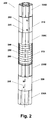
- FIG. 2 is schematic diagram of the magnetic assembly of the NMR tool in accordance with a preferred embodiment.
- FIG. 3A-3D provide various views of the static magnetic field flux lines, oscillating magnetic field flux lines, and sensitive volumes generated by the NMR tool of the embodiment illustrated in FIG. 2 .
- FIG. 3E illustrates the distribution of the static magnetic field strength and static magnetic field gradient as a function of distance from the tool.
- FIG. 4A is schematic diagram of the magnetic assembly of the NMR tool in accordance with a second embodiment.
- FIG. 4B illustrates static magnetic field flux lines and sensitive volumes generated by the NMR tool of the second embodiment.
- FIG. 5 is an elevated view of a transceiver antenna assembly in a preferred embodiment.
- FIG. 6 is top view of a transceiver antenna in a preferred embodiment, with direction of magnetic fields indicated.
- FIG. 7 shows sectional and elevated views of the transceiver antenna assembly in accordance with a second embodiment
- FIG. 7A shows a cross-sectional view.
- FIG. 8 illustrates a frequency-modulated CPMG pulse sequence used in one embodiment.
- FIG. 9 illustrates a schematic cross-sectional view of an antenna according to another embodiment.
- FIG. 10 illustrates the relative placement of sensitive volumes and a simulated monopole magnetic field.
- FIG. 11 schematically illustrates an example MRIL wireline tool (not to scale) placed against a borehole wall with standoffs and a bowspring.
- FIG. 12 illustrates six possible modes in one embodiment directed to obtaining directional resonance data.
- FIG. 13 provides comparison between data obtained with MRIL-Prime and directional MRIL tool embodiments.
- FIG. 14 illustrates results of the repeatability test comprising repeat logs of a well taken at different points in the borehole.
- FIG. 15 shows data from different sensitive volumes of the directional tool.
- FIG. 16 shows a cross section of a logging tool close to a side of a borehole and corresponds to the illustration in FIG. 11 .
- FIG. 17 illustrates directional drilling using a directional antenna configuration combined with the deep-looking capabilities in an exemplary embodiment.
- FIG. 18 provides an illustration of a general logging tool, including in a logging while drilling context.
- FIG. 19 shows an illustrative magnetic system, suitable for deployment in a borehole, with a single magnet and two attached soft magnetic poles, which system is suitable for generating substantially radial magnetic flux lines in a region of a formation about the magnetic system.
- FIG. 2 illustrates a preferred embodiment of an NMR tool, which is suitable for logging-while-drilling of a geologic formation.
- Tool 200 comprises the following components: two magnetic configurations each comprising a permanent magnet (magnets 210 and 220 ) positioned with like poles facing each other and a plurality of pole pieces 230 A, 230 B, 230 C, and 230 D (subsequently referred to as pole pieces 230 ), longitudinally extending one or both poles of a magnet.
- a RF transceiver antenna assembly 240 Interposed between the magnetic configurations is a RF transceiver antenna assembly 240 , which comprises a soft-magnetic core 250 and a plurality of coil windings 260 .
- Antenna assembly 240 is preferably surrounded by a protective shield 270 .
- tool 200 is mounted within a tubular drill collar (not shown) having mud flow conduit 285 therein to facilitate mud circulation in the borehole.
- magnets 210 and 220 are cylindrical magnets having a substantially circular cross section, each magnet being generally elongated and centered along the longitudinal axis 205 of the magnetic assembly 200 . In operation, this axis is usually aligned with the axis of the wellbore. Magnets 210 and 220 are preferably polarized in a direction parallel to the longitudinal axis of the magnetic assembly 200 and mounted with like magnetic poles facing each other. For each magnet 210 and 220 , the magnetic field lines travel as shown in FIG. 3B .
- the magnetic field lines extend radially in all azimuthal directions to create a static field B 0 in a substantially cylindrical region of the formation surrounding the borehole, as also shown in FIG. 3A . Because of the separation, the magnitude of the static magnetic field B 0 in the region between magnets 210 and 220 (in the vicinity of any given radius) is substantially homogeneous.
- Magnets 210 and 220 are preferably strong Alnico magnets with remanence induction of approximately 1.25 Tesla.
- Alnico magnets are composed primarily of alloys of Aluminum, Nickel, and Cobalt. Alnico materials are generally characterized by excellent stability over a wide temperature range, high residual induction, and relatively high energies. Such magnets are manufactured through either a casting or sintering process. Cast magnets may be manufactured in complex shapes, in a preferred embodiment magnets 210 and 220 are tubular (i.e., rod-shaped). It should be noted that sintered Alnicos offer slightly lower magnetic properties but better mechanical characteristics than cast Alnicos. For most practical purposes, either manufacturing method is suitable.
- the length of the magnets is preferably about 4-5 times of the diameter.
- magnets 210 and 220 are preferably about 13 cm in diameter and approximately 60 cm long. It should be understood by those of skill in the art that the length of the magnets may vary depending on the specific design needs, provided of course that the magnet's length-width ratio is selected to optimize its performance.
- the above-described Alnico magnets are manufactured, for example, by the Alnico Products Division of Group Arnold, magnetic products group of SPS Technologies, Inc. based in Marengo, Ill.
- magnets 210 and 220 may comprise permanent magnets, such as hard ferrite (SrO-6(Fe 2 O 3 )) magnets having strontium carbonate and iron oxide composition, neodymium-iron-boron (NdFeB) magnets, or samarium cobalt (SmCo) magnets.
- magnets 210 and 220 may comprise electromagnets that are made of thin-gauge copper or aluminum foils.
- the shape of magnets 210 and 220 may vary depending on the specific design need, for example, it may be a solid cylinder or a cylindrical annulus (i.e., tubular).
- magnets may be integral, or may comprise a plurality of smaller magnets bonded together.
- magnetization direction of each smaller magnet may vary as long as total magnetic moment is aligned longitudinally with the axis of the magnetic configuration 200 and like poles of magnets 210 and 220 face each other.
- the above-described magnets and variations thereof are can be made, for example, by Group Arnold, magnetic products group of SPS Technologies, Inc. based in Marengo, Ill.
- magnets 210 and 220 are extended at one or both poles by a plurality of pole pieces 230 (see pole pieces 230 A, 230 B, 230 C, and 230 D in FIG. 2 ).
- a pole piece in this application is a piece of (ferromagnetic) material attached to one end of a magnet and so shaped that the distribution of the magnetic flux in the adjacent medium is appreciably controlled.
- Pole pieces 230 are composed of high permeability material, preferably greater than about 100. Suitable materials for the pole pieces may comprise iron, permeable steel or other soft-magnetic alloy of iron and nickel. In the specific embodiment discussed above, pole pieces are cylindrically shaped rods about 30 cm long (which may vary depending on the specific design requirements).
- Pole pieces 230 may be attached to a magnet pole face by adhesive bonding or with studs or bolts. For greater efficiency, a non-magnetic gap between the magnet poles and the pole pieces 230 should be as minimized, and preferably made as small as practically possible. While the pole pieces can be allowed to carry some load, the connection between pole pieces 230 and magnets 210 and 220 should be done in a manner that minimizes the structural load on the magnets.
- pole pieces 230 shape the static magnetic field B 0 generated by magnets 210 and 220 .
- the magnetic field lines travel outward from an end of the magnet through the respective inner set of pole pieces 230 and into the formation, and travel inward to the other end of the magnet.
- pole pieces 230 make the magnetic field intensity more uniform and homogeneous in the annular regions of the formation surrounding the borehole.
- the longitudinal separation between the inner pole pieces of magnets 210 and 220 is about 80 cm.
- the amount of separation between magnets 210 and 220 is determined based on several factors, including: (1) selecting the requisite magnetic field strength; (2) received depth of investigation; and (3) generating a field having small radial variations in the region of interest so that the echoes received during a pulse sequence are less sensitive to lateral tool motion.
- the separation between magnets 210 and 220 decreases, the magnetic field becomes stronger and less homogeneous.
- the separation between magnets 210 and 220 increases, the magnetic field becomes weaker and more homogenous.
- FIG. 3E illustrates how the field strength (B 0 ) and field gradient (G 0 ) of the static magnetic field change as functions of radius (R) from the tool in accordance with a preferred embodiment.
- magnetic assembly 200 provides higher field strengths and lower field gradients further away from the tool than prior art NMR tools.
- magnetic assembly 200 imparts an azimuthally symmetric static magnetic field B 0 suitable for measuring NMR signals in a region extending 20 cm away from the tool to about 80 cm and beyond into the formation, in some instances about 1 meter deep.
- prior art discloses field strengths of about 10 G or lower at a distance of 30 cm from the tool.
- an embodiment of the tool in accordance with the principles disclosed in this application shows field strength of over 10 G at 80 cm or more away from the tool.
- FIG. 18 A general structure of the logging tool in a specific embodiment is shown in illustrative FIG. 18 .
- Borehole 1800 in formation 1805 has logging tool 1810 comprising magnet 1815 with pole piece 1820 .
- Antenna core 1825 has antenna coils 1830 with the antenna assembly protected by antenna sleeve 1835 .
- the antenna is mounted on yoke 1845 .
- the deep looking logging tool is able to collect data from shallow sensitive volume 1850 and deep sensitive volume 1855 .
- the entire magnet and antenna assembly may be mounted on a drill collar 1860 in a LWD application.
- flow channel 1840 which is important for use of the logging tool 1810 while drilling to allow mud to flow to the drill bit.
- FIG. 2 with two opposed magnets, although preferred, may be replaced to a good approximation by a single magnet with pole extended by pole pieces.
- the shaping of the magnetic flux lines by pole pieces even in the absence of opposing poles provides a substantially radial magnetic field in a portion of the formation surrounding a borehole.
- useful NMR data may be obtained for sensitive volumes in the vicinity of a logging tool with a single permanent magnet having pole pieces. This simplifies the construction of a suitable magnet that provides a good approximation to magnetic flux lines directed outwards in a substantially radial direction.
- Tool 400 comprises a single permanent magnet system having a tubular, axially polarized magnet 405 and one or more soft-magnetic pole pieces 410 A and 410 B extending the poles of magnet 405 .
- Tool 400 further comprises a RF transceiver antenna 415 surrounding one or more pole pieces 410 A.
- Antenna 415 comprises antenna core 420 and one or more antenna coils 425 wound around core 420 .
- Tool 400 may further comprise another antenna 430 surrounding one or more pole pieces 410 B.
- Antenna 430 may also comprise antenna core 435 and one or more antenna coils 440 .
- tool 400 is mounted on a tubular drill collar 445 having a mud flow channel therein.
- FIG. 19 shows another view of the magnet configuration in this embodiment.
- logging tool 1900 has central channel 1905 , optional antenna core 1910 adjacent to pole piece 1915 extending a pole of magnet 1920 .
- the other pole of magnet 1920 is extended by pole piece 1925 , which is adjacent to core 1930 with wound coil 1935 forming an antenna.
- a pole piece preferably iron, may be used doubling as an antenna core and pole extender.
- the magnetic components of the tool 400 are preferably made of substantially similar materials and have substantially similar magnetic and electrical characteristics as the corresponding components in the tool 200 of the embodiment, which was described above.
- FIG. 4B shows the flux lines of the NMR tool 400 .
- the tool 400 creates two sets of the sensitive regions suitable for NMR measurements.
- the two sensitive regions are located in front of upper and lower soft magnetic poles 410 A and 410 B. In these regions, the direction of the static field is substantially radial.
- FIG. 4B only one region of the nested sensitive volumes (SV) is denoted in front of the pole pieces 410 A.
- the shapes of the sensitive volumes are different from ideal cylinders and their boundaries are not exactly parallel to the tool's axis.
- the proximal ends of the inner pole pieces 230 are attached to a yoke (not shown).
- the yoke may have cylindrical shape with its longitudinal axis aligned in coincidence with the axis of the tool 100 .
- pole pieces 230 are not joined rigidly with the yoke, but can move some against each other to provide overall bending flexibility.
- the entire magnetic assembly is symmetric around the yoke.
- the length of the yoke is preferably about 80 cm.
- the length of the entire magnetic assembly in this embodiment is about 315 cm.
- the yoke may provide support for RF transceiver antenna 240 , as described next.
- the yoke is preferably made of a mechanically durable soft-magnetic material.
- magnetic assembly 200 further includes transceiver antenna 240 mounted on the yoke or directly on drill collar 280 .
- Transceiver antenna 240 comprises antenna core 250 and coil windings 260 .
- Core 250 is preferably shaped as an annular cylinder with drill collar 280 (or yoke) passing through the longitudinal cavity extending within core 250 .
- the total length of core 250 is about 72 cm.
- core 250 preferably comprises several rings stacked on a drill collar (or yoke) 280 .
- the rings are preferably made of soft-magnetic material having high magnetic permeability.
- the soft-magnetic rings may be made from soft ferrite, ferrite polymer composites, powdered iron or nickel cores, etc.
- core 250 has magnetic permeability of about 100. It is important that the core material maintains its permeability to limit RF power losses and does not saturate due to the static magnetic field B 0 generated by magnets 210 and 220 . It will be appreciated that the permeability values of core 250 may vary depending on the specific design requirements.
- core 250 shapes the static magnetic field generated by magnets 210 and 220 in the sensitive region.
- core 250 enables even and azimuthally symmetric distribution of magnetic field lines along its entire length. As a result, magnetic field intensity is distributed evenly along core 250 , which makes the static magnetic field B 0 more uniform in a plurality of sensitive volumes extending as far as one meter into the formation surrounding the borehole, as shown in FIG. 3A .
- RF transceiver antenna assembly 500 comprises at least three coil windings 510 , 520 , and 530 wound around antenna core 550 (corresponding to core 250 in FIG. 2 ).
- Antenna coils 510 and 520 are preferably saddle coils, each having one or more windings. Saddle coils 510 and 520 are preferably rotated 90° with respect to each other along the longitudinal axis of the tool (z-axis in FIG. 5 ), so that coil 510 is substantially co-planar with the x-axis, and coil 520 is substantially co-planar with the y-axis.
- Antenna coil 530 is a solenoid, preferably having a plurality of windings lying in planes substantially orthogonal to the longitudinal axis of the tool.
- solenoid coil 530 comprises eight-windings having total inductance of about 27 ⁇ H.
- two or more solenoid coils having different inductances may be used.
- antenna 500 is suitable for azimuthally symmetric and directionally sensitive NMR signal detection.
- the transmitter output signal may be routed to either one of the coils.
- solenoid coil 530 is used to impart RF field B 1 orthogonal to the static field B 0 in the entire sensitive volume
- saddle coils 510 and 520 are used to impart RF field B 1 orthogonal to the static field B 0 in restricted sections of the sensitive volume.
- the NMR signals from all three coils are preferably detected, amplified, and processed, as discussed below.
- coils 510 , 520 , and 530 may be combined in a plurality of configurations for transmitting RF pulses and for receiving NMR signals from shallow and the deep volumes. Moreover, two or more solenoid coils having different lengths (i.e., number of windings) may be used to excite NMR signals in shallow and deep volumes.
- a solenoid coil 530 is preferably used.
- the coil When RF power pulses are conducted through solenoid coil 530 , the coil generates an RF equivalent magnetic dipole centered at the origin and directed along the z-axis, as shown in FIG. 3C .
- the equivalent magnetic dipole generates an RF magnetic field directed opposite to the dipole direction and of substantially equal amplitude within a sensitive volume in the formation (the sensitive volume is a cylindrical shell with thickness determined by the bandwidth of the RF pulse). Since axially-oriented B 1 field lines are substantially orthogonal to the radially-oriented static magnetic field B 0 in all azimuthal directions, the nuclear magnetic resonance is induced in the entire sensitive volume.
- Saddle coils 510 and 520 can be used in a specific embodiment to achieve azimuthally focused nuclear magnetic response in the surrounding formation.
- RF power pulses When RF power pulses are conducted through saddle coils 510 and 520 , they produce RF dipole in a direction transverse to the longitudinal axis of the tool.
- saddle coils 510 and 520 generate radially-oriented B 1 field lines orthogonal to the static field B 0 along their respective planes. (This characteristic is exploited to provide directional sensitivity to the antenna 500 , as discussed below.)
- saddle coil 510 may be sensitive in the east-west direction
- saddle coil 520 may be sensitive in the north-south direction as indicated in FIG. 3D .
- core 550 significantly improves the efficiency of RF antenna 500 by offsetting the reduction in the antenna aperture due to the presence of conductive drill collar 580 (or yoke).
- coil windings of antenna 500 are magnetically coupled to ferromagnetic core 550 such that, when the electrically conductive coils 510 , 520 , and 530 are energized with AC current, a magnetic dipole of increased magnetic moment is formed in core 550 , thereby increasing the strength of RF magnetic field B 1 .
- antenna 500 is capable of generating a much larger magnetic moment than typical nonmagnetic-cored antenna, for the same power input.
- the illustrative antenna of the first embodiment is but one of many possible antenna configurations. Some illustrative examples of directional antennas including those using combinations of multiple solenoids are described next.
- the antenna assembly 700 in accordance with a second embodiment is set on a ribbed yoke 710 .
- the yoke 710 has a plurality of guide projections 715 , which are formed along its outer surface.
- the guide projections 715 extend outwardly away from opposite sides of yoke 710 , as illustrated, and are spaced apart from one another at a predetermined interval along the longitudinal extent of yoke 710 .
- Guide projections 715 are positioned to form two or more spaced-apart rows of guide projections along each side of yoke 710 , with each row extending along the length of yoke 710 .
- three guide projections are formed on the surface of yoke 710 , thereby creating three spaced-apart rows.
- three generally centrally positioned grooves or recessed region 720 are provided along the outer periphery of yoke 710 , extending along of the sides of yoke 710 , as well as along the opposite ends of yoke 710 .
- the surface of yoke 710 is preferably coated with copper, which provides an RF screen.
- the copper screen can be extended up to the inner diameter of the antenna sleeve 750 , which preferably encloses the entire antenna assembly 700 , to reduce the magnetic coupling between antenna coils 730 .
- the radial extension of the RF screen in the space between the adjacent coils 730 allows for correction of the RF field pattern close to the tool.
- the air gap between core segments 725 has insignificant influence on the field variations within the deep sensitive volume.
- antenna assembly 700 in accordance with a second embodiment comprises two or more core segments 725 adjacent to yoke 710 and extending longitudinally within recessed regions 720 along the surface of yoke 710 .
- the shape of each core segment 725 resembles a sector of a tubular cylinder cut along its longitudinal axis. Core segments 725 are separated from each other by guide projections 715 of yoke 710 .
- Core segments 725 are preferably made of soft-magnetic material(s) having high magnetic permeability.
- the soft-magnetic core sectors 725 may be made from soft ferrite, ferrite polymer composites, powdered iron or nickel cores, or others.
- core 725 has magnetic permeability of about 100. It is important that the core material maintains its permeability to limit RF power losses and do not saturate due to the static magnetic field B 0 generated by the magnetic assembly (not shown). It should be understood that the permeability of core 725 may be different depending on the specific design requirements. It is desirable, however, that all core sectors 725 be made of the same material and have the same permeability.
- Antenna assembly 700 further comprises a plurality of antenna coils 730 wound around core segments 725 .
- each core segment 725 carries at least one antenna coil 730 .
- Each antenna coils 730 resembles a deformed solenoid.
- Each coil 730 preferably has a plurality of windings lying in planes substantially orthogonal to the longitudinal axis of the tool.
- each coil 730 comprises of the same winding having with a small magnetic coupling between the coils.
- two or more solenoid coils having different inductances may be used. Since coils 730 are wound in transverse planes, the produced RF field is similar to the RF field produced by a solenoid. To this end, coils 730 are preferably substantially similar and carry similar currents.
- Antenna 500 is preferably suitable for azimuthally symmetric and azimuthally focused NMR detection.
- transmit mode azimuthally uniform excitation of the formation is desired.
- all coils 730 may transmit in parallel.
- coils 730 generate an RF equivalent magnetic dipole centered at the origin and directed along the longitudinal axis of the tool. Since the axially-oriented B 1 field lines are substantially orthogonal to the radially-oriented static magnetic field B 0 in all azimuthal directions, NMR is induced in the entire sensitive volume.
- the signals from all coils are detected, amplified, and processed separately.
- a typical pulse sequence would be based on the CPMG sequence; a specific pulse sequence is described below.
- the echo signals received by each coil correspond to subtending sectors of the sensitive volume. Certain azimuthal overlapping of the sensitive volume sectors may exist and should be considered during data processing and log interpretation. Radial extensions of the RF screens within recess regions 720 between the adjacent coils 730 allow some control over how much adjacent sectors overlap. By increasing the number core sectors 725 , it is possible to achieve a fine azimuthal resolution on the NMR sensor.
- antenna assembly 240 (or 700) is enclosed in a sleeve 270 .
- An example construction of antenna sleeve 270 is described, for example, in U.S. Pat. No. 6,008,646, which is incorporated herein by reference.
- sleeve 270 is suitable to protect antenna assembly 240 against abrasions from particles in the drilling mud and impact against the earth formation.
- sleeve 270 is composed of a non-conductive, impact and wear resistant material, such as fiberglass or transition toughened zirconia.
- sleeve 270 may be composed of steel.
- sleeve 270 should preferably have vertical slots cut therein at the top and the bottom of the antenna 260 to allow flux of magnetic field B 1 to enter and exit the magnetic assembly.
- shield 270 may be extended to cover the entire magnetic assembly 200 .
- FIG. 9 illustrates another embodiment of an antenna assembly in accordance with the principles disclosed herein, with four longitudinal segments (strips) interconnected at one of their end.
- This strips' arrangement allows NMR investigation of four quadrants about an axis of the logging tool.
- it is useful for determining directional properties of the surrounding formation with the aid of signals received at two or more, preferably adjacent antenna strips.
- antenna assembly 900 comprises four longitudinal strips 930 A, 930 B, 930 C, and 930 D spaced apart by 90 degrees and interconnected by means of an end ring 910 . On the opposite end of the strips, four antenna terminals are located (T 1 , T 2 , T 3 , and T 4 ).
- antenna assembly 900 can include an antenna core placed inside the strips.
- the four terminals (T 1 , T 2 , T 3 , and T 4 ) of the antenna 900 can be connected to transmitter in eight different fashions: T 1 +T 2 , T 2 +T 3 , T 3 +T 4 , T 4 +T 1 , T 1 +T 3 , T 2 +T 4 , T 1 &T 2 +T 3 &T 4 , and T 1 &T 4 +T 2 &T 3 .
- the terminals of the antenna 900 that are not currently connected to transmitter can be shunted.
- the RF field produced by antenna 900 is similar to that of a saddle shaped antenna. For example, in order to get an RF field pattern shown in FIG.
- T 1 &T 2 +T 3 &T 4 strips combination should be connected to transmitter (T 1 &T 2 means that two antenna terminals, T 1 and T 2 , are shunted and connected to first transmitter terminal, while T 3 &T 4 means that another two antenna terminals, T 3 and T 4 , are also shunted and connected to second transmitter terminal).
- This antenna design further breaks down the typically concentric sensitive volumes into four azimuthally-distinguishable quadrants.
- This antenna enables operation in large (121 ⁇ 4 in. and up) and potentially badly washed-out boreholes.
- This design also exploits the simulated-monopole static magnetic field discussed above.
- the magnetic monopole is simulated by the radially directed static magnetic field capable of reaching deep into the formation.
- a magnetic monopole is simulated by a logging tool having a substantially radial static magnetic field extending beyond about 60 cm into a formation surrounding the logging tool.
- FIG. 10 illustrates the relative location of sensitive volumes 1000 in a simulated monopole magnetic field represented by static magnetic field lines 1005 .
- radial separation between sensitive volumes is achieved by switching operating frequencies to selectively excite resonance at different radii.
- deploying the example antenna configuration disclosed herein there are five (5) radial depths possible and four (4) azimuthal positions for a total of twenty (20) distinct sensitive volumes that may be addressed by the antenna.
- N-S and E-W there are two omnidirectional modes
- N, S, E and W four directional modes
- N, S, E and W the omnidirectional modes
- N, S, E and W the directional modes
- individual quadrants are not being addressed; instead, two adjacent or all four quadrants resonate simultaneously.
- the signals from each measurement are, typically, not independent of each other. Decomposition into independent quadrant readings requires some additional steps, which are outlined below.
- Table 2 above lists comparable values for the directional design. As is readily seen, the frequencies have dropped by 200-250 kHz, and the gradient values are roughly cut in half. Therefore, all calculations that either explicitly calculate diffusivity values or otherwise rely on diffusion contrast to differentiate between fluid types are modified to take into account this change. Alternatively, the reduced magnetic field gradient can be compensated for by an increase in echo-to-echo spacing (T e ). The ratio of new echo spacing for the directional tool to that for omnidirectional familiar near borehole investigating tools should equal the ratio of new (and lower) field gradient to the old field gradients.
- FIG. 12 illustrates six modes A-F of operation for the directional antenna having four longitudinal strips ( FIG. 9 ). Also shown in FIG. 12 are sensitive volumes 1200 for each of the modes A-F. Each of the sensitive volumes corresponds to a different frequency NMR signal.
- FIG. 12 although a plurality of sensitive volumes are depicted in the illustrative figures, this is not intended to be a limitation on the scope of the attached claims unless so indicated expressly.
- FIG. 12 although not marked as such is a schematic antenna core in cross-section.
- FIG. 16 shows a cross-sectional view of borehole 1600 in formation 1605 with sensitive volumes 1610 in the formation. Also shown are logging tool 1615 with central channel/cavity 1620 and bowspring 1625 .
- FIG. 11 provides a side illustration of the tool.
- logging tool 1615 can collect data in washed out and asymmetric boreholes with relative ease due to the ease of fixing its position in asymmetric and irregular washed out boreholes.
- FIG. 1 illustrates in a block-diagram form the preferred electronics arrangement for the NMR tool.
- transceiver RF antenna 110 is coupled to tuning capacitors (not shown) housed in a compartment 115 , which is interfaced to a transmit/receive switch 120 .
- T/R switch receives pulsed RF power from transmitter 140 , which is gated by pulse generator 145 .
- Pulse generator 145 is under control of computer/signal processor 150 .
- Pulse generator 145 controls the timing and operation of transmitter 140 , which is powered by power supply 155 .
- T/R switch 120 routes the received NMR signals to preamplifier 125 , which in turn drives the receiver 130 .
- the received, amplified signal is digitized in digitizer 135 and fed into computer/signal processor 150 .
- tuning capacitors are housed in a compartment 115 .
- Tuning capacitors are preferably used to match the impedance of transceiver antenna 110 so that it will resonate at the desired natural frequency.
- compartment 115 is sealed off from the borehole environment, so that the capacitors remain at atmospheric pressure instead of being exposed to the high borehole pressures. This pressure-sealed design eliminates the need for filling the compartment 115 with oil, as in prior art, to prevent the capacitors from contacting borehole fluids.
- a high-pressure antenna feed-through connector (not shown) is provided to establish a conductive path for the electrical current from transceiver antenna 110 to the tuning capacitors.
- more pressure-sensitive electronics may be mounted inside compartment 115 .
- Such an arrangement is advantageous because by changing the operating frequency, a different sensitive volume is selected. By using multiple volumes one at a time, more signals can be accumulated in less time and/or different NMR measurements can be performed in a quasi-simultaneous fashion.
- processor 150 receives real-time motion data from the motion sensor interface 185 , which conditions the electrical signal from a plurality of motion sensors (not shown). The operation of the motion sensors is described in more detail in U.S. Pat. No. 6,362,619, which is incorporated herein by reference. Additionally, the processor reads from and writes to a non-volatile data and program memory 190 . In a preferred embodiment, non-volatile memory 190 retains data even when the electronics is not supplied with electrical power. In a preferred implementation, non-volatile memory 190 uses “Flash” EEPROM integrated circuits. Another suitable option is a battery-powered low-power CMOS static RAM. Non-volatile memory 190 holds all data acquired during a run. Processor 150 performs real-time processing on the data to extract an indication of formation porosity and of log quality.
- this data is converted into a data stream of preferably low bit rate and are fed into a mud-pulse system 195 that broadcasts the data stream to the surface by means of pressure pulses within the fluid column within the drill collar.
- Above-surface processing equipment (not shown) can be used to display the results to an operator. It will be appreciated that different tool-to-surface communication approaches are possible in alternative embodiments. Further, those skilled in the art will appreciate that downhole processor 150 may be implemented using two or more dedicated signal processors communicating with each other. In this embodiment, each processor can be performing a different task.
- a dedicated processor can be used to measure the orientation of the tool with respect to earth coordinates (inclination from static acceleration and strike from the magnetic north direction), compute necessary parameters for directional drilling system, and process signals from various antenna elements to enable directional sensitivity. It is applicants' intention that any suitable processor configuration can be used in accordance with the principles described in this disclosure. Further, it should be apparent that various options that exist for storage of the acquired information and its communication to a user can be used in different practical embodiments.
- FIG. 1 also illustrates the power generation in a block diagram form.
- this power could be derived from one or more of the following sources: (1) from a turbine/generator combination 175 and 180 that converts a portion of the mechanical energy delivered by the flowing mud column into electrical energy, or (2) an (optional) bank of primary battery cells (not shown), typically of the lithium type.
- the generator can be used to directly drive the power conversion unit 170 .
- a potential disadvantage of this arrangement is that the tool cannot operate without mud being continuously pumped from the surface through the drill collar through the NMR tool to the drill bit. This requirement could potentially interfere with the requirements of the drilling operation.
- the turbine/generator combination is used to charge a bank of rechargeable secondary battery cells 165 , for example of the nickel-cadmium or silver-oxygen type.
- the generator 175 is sufficiently powerful to recharge the secondary elements in a short amount of time, while these secondary cells supply electric power to the tool during the time when no or very slow mud flow exists.
- NMR measurements can be taken in shallow and deep volumes. As indicated above, measurements in deep sensitive volumes are primarily enabled by a strong static magnetic field B 0 having low field gradient G 0 . As shown in FIG. 3E , magnetic field B 0 decreases as the distance from the tool increases. For example, 20 cm from the tool's axis the magnetic field B 0 is about 62 G; 80 cm from the tool's axis B 0 falls to about 14 G.
- the frequency of the oscillating field B 1 is selected to match the Larmor frequency of the protons at that distance.
- a narrow frequency band is typically chosen, so that the sensitive volume is a thin cylindrical shell co-axial with the tool and surrounding the borehole.
- the NMR system in accordance with a preferred embodiment conducts measurements in at least two sensitive volumes.
- such sensitive volumes differ in 20 cm and 30 cm boreholes.
- the preferred sensitive volumes are identified in Table 4 below:
- Shallow and deep measurements in general serve different purposes.
- shallow volumes i.e., 20 cm for smaller boreholes and 30 cm for larger boreholes characterize flushed conditions.
- these volumes are used to replicate the conventional NMR logging measurements, such as porosity, T 1 and T 2 relaxation measurements, bound fluid volume, etc. These measurements characterize the pore space, the type and volume of bound fluids and volume available for producible (movable) fluids.
- these shallow volumes can be used for invasion profiling.
- the deep measurements i.e., 80 cm deep) enable hydrocarbon quantification in the deep regions that are free of borehole fluids.
- deep readings in a preferred embodiment, can be used to supplement the shallow free-fluid measurements by quantifying the amount of oil and gas present at a distance from the borehole.
- different combinations of at least one shallow and at least one deep measurement (and in other embodiments additional measurements at intermediate depths) enable a single magnet assembly built in accordance with the principles outlined above to provide a depth-model of the formation surrounding the borehole.
- it enables estimation of the borehole fluid invasion profile, along with standard porosity measurements predominantly obtained from shallow volume measurements, and producible hydrocarbon saturations, primarily obtainable from deep volume measurements.
- a significant advantage of the proposed single magnet assembly design is that all of these measurements can be obtained quisi-simultaneously, thus essentially obviating the need for separate logging runs, the possibility of depth mismatching, etc.
- the NMR tool is capable of directional NMR detection.
- the directional sensitivity of the tool is provided by a RF transceiver antenna 500 and a novel data processing method.
- the RF antenna imparts an azimuthally symmetric or azimuthally focused RF field B 1 within the zone of investigation.
- the RF antenna 500 becomes azimuthally sensitive.
- the data processing method in a preferred embodiment enables analysis of the received NMR signals to determine which region of formation is characterized by a given NMR response.
- the directional sensitivity aspect of this application in combination with conventional accelerometer and magnetometer readings, enables real-time payzone steering during borehole drilling.
- FIG. 5 illustrates a three-coil RF transceiver antenna 500 in accordance with one embodiment.
- antenna 500 comprises two saddle coils 510 and 520 , and a solenoid coil 530 wound around soft-magnetic core 550 .
- solenoid coil 530 when energized with AC current, produces oscillating field B 1 having vertical field lines (coming out of the paper plane), which are azimuthally orthogonal to the static magnetic field B 0 . As a result, the entire sensitive volume is resonated. Subsequently, solenoid coil 530 is capable of detecting NMR signals from the entire resonance volume.
- saddle coils 510 and 520 are azimuthally sensitive.
- saddle coils when saddle coils are energized with AC current, they produce oscillating field B 1 with magnetic field lines substantially orthogonal to the static magnetic field B 0 along their respective planes; in FIG. 6 , for example, saddle coil 510 is capable of inducing NMR in regions along the x-axis, while saddle coil 520 is capable of inducing NMR in regions along the y-axis.
- the directions of B 1 magnetic field lines produced by coils 510 and 520 are indicated in FIG. 6 as B 510 and B 520 , respectively.
- coils 510 and 520 may be used to detect NMR signals from the resonated sections of the sensitive volume.
- antenna configuration 500 effectively divides the entire resonance volume of 360° into four measurement quadrants: A, B, C, and D, each covering sectors of approximately 90°.
- solenoid coil 530 is suitable for detecting NMR signals from all four quadrants.
- Saddle coil 510 is suitable for detecting NMR signals from quadrants A and C, in which its magnetic field B 510 is substantially orthogonal to static field B 0 .
- Saddle coil 520 is suitable for detecting NMR signals from quadrants B and D, in which its magnetic field B 520 is substantially orthogonal to static field B 0 . It should be noted that since coils 510 , 520 , and 530 are independent, the NMR echoes can be received through the coils simultaneously.
- all three coils may be used for transmission and reception resulting in nine possible measurements, shown in Table 6 below. (For clarity, in the remainder of this section coil 510 will be denoted as X, coil 520 will be denoted as Y, and coil 530 will be denoted as Z).
- the first type of response occurs when solenoid coil 530 is used both for transmission and reception (ZZ) resulting in an omnidirectional response. In this measurement, all four quadrants are resonated and NMR signals are also detected from all four quadrants (A+B+C+D).
- Such an omnidirectional response of solenoid coil 530 may be used as a reference for saddle coil measurements; in particular, it may correspond to a maximum 100% response in a water tank.
- the second type of volume response occurs when: (1) the solenoid coil is used for transmission and either one of saddle coils is used for reception (ZX and ZY), or (2) either one of the saddle coils is used for transmission and solenoid coils is used for reception (XZ or YZ).
- a sign change takes place due to the relative orientation of B 0 , B 1 (transmit, solenoid), and B 1 (receive, saddle coil). Accordingly, in a homogeneous medium, the spin signals would cancel out. In a heterogeneous medium, however, spin signals will indicate the presence of a difference between opposing quadrants.
- the third type of volume response occurs when either one of the saddle coils is used both for transmission and reception, resulting in an azimuthally focused response.
- coil 510 is used both for transmission and reception (XX)
- azimuthally focused sections along the x-axis are resonated: namely, quadrants A and C are resonated.
- coil 520 is used both for transmission and reception (YY)
- azimuthally focused sections along the y-axis are resonated: namely, quadrants B and D are resonated.
- the fourth type of response occurs when one saddle coil is used for transmitting and the other is used for receiving (XY or YX).
- resonance volumes overlap along quadrant diagonals due to the orthogonality of saddle coils 510 and 520 and decrease in radial sensitivity of saddle coils with increase in angular deviation from its planes.
- the received NMR signal is weak and unsuitable for accurate measurement.
- the first three volume responses may be used in accordance with a preferred embodiment to provide directional sensitivity.
- the excitation pulses are alternately transmitted through each antenna coil.
- the NMR signals from all three coils are detected and amplified.
- they are processed to generate five signal components (i.e., quadrant signatures) A, B, C, D, and the onmidirectional signal.
- the quadrant signatures may be computed by constructing and solving systems of linear equations from data provided in Table 6, as shown below.
- ZX measurement may be interchanged with XZ measurement, and YZ measurement with ZY measurement.
- quadrant signatures may by derived by forming and solving an over-determined matrix, as shown below.
- Eq. 4 provides linear form of quadrant signatures given in matrix form in Eq. 3.
- A 1 ⁇ 6(2 XX+ 3 ZX ⁇ YY+ZZ )
- B 1 ⁇ 6( ⁇ XX+ 2 YY+ 3 ZY+ZZ )
- C 1 ⁇ 6(2 XX ⁇ 3 ZX ⁇ YY+ZZ )
- D 1 ⁇ 6( ⁇ XX+ 2 YY ⁇ 3 ZY+ZZ )
- the directional signal components may be assigned to four quarter-cylinders located around the borehole by simultaneously measuring the orientation of the tool with respect to earth coordinates (inclination from static acceleration and strike from the magnetic north direction). In a vertical borehole, these quarter-cylinders cover the compass directions (i.e., North, South, East, and West). In a horizontal borehole they correspond to the directions above, below, left, and right.
- These tool orientation parameters are typically determined by accelerometers and magnetometers disposed within the tool string and measuring earth's gravitational vector compass directions, respectively.
- Table 3 illustrates several modes of operation including four directional modes and two omnidirectional modes.
- the directional modes it is preferable to account for interactions between antennas, reflected in two adjacent (or close together) antenna segments receiving NMR signals from more than one sensitive volume quadrant.
- a directional antenna has six radiation patterns. In any of these modes, the NMR signal comes from either four or two quadrants in omnidirectional and in directional modes, respectively. For example, if the antenna radiates in North (N) direction, the signal comes from the north-easterly and north-westerly quadrants.
- the entire processing chain from NMR echoes to the log quantities, porosity, bound fluid volume, etc. is, preferably, carried out in the original NESW space.
- the backprojection is only performed at the level of log curves, which are all bound to be non-negative quantities.
- An interpretation of the quantities N, E, S, W and NE, SE, SW, NW is that they stand for log data quantities such as NMR porosity, bound fluid porosity, etc. At this level:
- Track 1 displays the Gamma Ray log and the minimum and maximum diameters.
- Track 2 presents data acquired with Halliburton's MRIL Prime tool at a logging speed of 15 ft/min.
- Track 3 and 4 shows long (8 s) and short (1 s) wait time logs recorded with the directional antenna of FIG. 9 .
- Track 3 also displays Neutron/Density porosity.
- the directional antenna logs were acquired at a logging speed of about 9 ft/min.
- the dark areas in tracks 2 - 4 denote free fluid, the light gray areas represent capillary bound fluid, and the intermediate gray areas stand for clay bound fluid.
- FIG. 14 shows the results from seven different runs in a repeatability test (both up- and down-logs).
- Track 3 shows the toolface orientation, where 0° (or 360°) indicates that the sensor is facing downwards. The results were nearly identical.
- track 2 of FIG. 14 seven repeats of the upper section are shown. All results are in very good agreement.
- the standard deviation of total porosity is about 1 pu.
- FIG. 15 shows illustrative data from different sensitive volumes, in particular the long-wait-time (8 s) data from four different sensitive volumes. These four volumes are used to acquire dual-wait-time data (1 s and 8 s) at an echo spacing of about 1.2 ms. The fifth volume is used for the high-precision claybound porosity measurement at echo spacing of about 0.6 ms. Data from the upper section and a lower section of the well are presented separately. Where the well is in fair condition, that is, where the well is round or elliptical without washouts, the NMR amplitudes from the four volumes agree with each other.
- the innermost volume contains a larger amount of borehole signal than the outermost volume.
- the borehole signal appears as free fluid.
- the inner volumes tracks to the left
- the outer volumes tracks to the right.
- DOIs Depth of Investigations
- the actual NMR amplitudes in the washouts are indicated by numbers. The pattern of monotonically decreasing amplitudes is characteristic of washouts and is useful for assessing whether or not the NMR porosity is affected by borehole signal.
- directional data is useful for determining a path for directing a drill into a formation region of interest.
- Shown in FIG. 17 is a sand layer interposed between a two shale deposits with a drill head 1700 traversing the sand layer.
- a corresponding set of signals is shown to indicate the directing of the drill head based on the acquired directional data including deep looking data that is required for effective directional drilling with the aid of NMR data.
- antenna configuration in FIGS. 5 and 9 effectively divides the entire resonance volume of 360° into four measurement quadrants: A, B, C, and D, each being approximately 90°.
- a position of the hydrocarbon deposit can be narrowed down to one or more quadrants.
- solenoid coil 530 is suitable for detecting NMR signals from all four quadrants
- saddle coil 510 primarily detects NMR signals from quadrants A and C
- saddle coil 520 similarly detects NMR signals from quadrants B and D.
- solenoid coil 530 and saddle coil 510 detect a relatively strong signal while saddle coil 520 typically fails to detect a signal from the deposit in quadrant A.
- all three coils may be used for transmission and reception resulting in nine possible measurements.
- Such information about the location of hydrocarbon deposits relative to the logging tool may be advantageously used in directional drilling to direct a drill towards quadrant A, including by using the antenna arrangement shown in FIG. 9 .
- the directing of the drill can be accomplished using a feedback mechanism based on acquired NMR data, particularly deep NMR data that is most effective in reliably locating formation properties away from the potentially compromised neighborhood of the tool.
- the NMR relaxation time measurements are determined using longitudinal relaxation times T 1 .
- the T 1 pulse sequence is designed to improve signal-to-noise ratio of NMR signals from the deepest volumes of the formation.
- the pulse sequence comprises at least one radio frequency pulse sweeping through a relatively wide range of frequencies to saturate the nuclear magnetization in a cylindrical volume around the tool; transmitting a frequency-swept readout pulse followed by a predetermined wait time; applying at least one frequency-swept refocusing pulse following the readout pulse; receiving at least one NMR echo corresponding to the readout pulse.
- one or more radio frequency pulse sweeping through a relatively wide range of frequencies is generated to saturate the nuclear magnetization in a cylindrical volume around the tool.
- the saturation pulse has bandwidth of about 10 kHz, duration of about 20 ms and sweeping rate of about 500 Hz/ms at full amplitude.
- Such saturation pulse generates B 1 magnetic field with gradient of about 0.3 G/cm in an annular region of about 6.5 cm wide.
- changing the range of RF frequencies varies the position and the width of the sensitive region in the formation.
- the saturation pulse is followed by a variable saturation recovery delay and a read-out pulse sequence.
- the readout pulse sequence preferably comprises a 90° pulse (i.e., excitation pulse) and a 180° pulse (i.e., refocusing pulse), followed by data acquisition window.
- the steps of applying a 180° pulse and data acquisition window are may be repeated.
- the 90° pulse and 180° pulse are frequency-swept. More specifically, the 90° pulse is about 8 ms long, sweeping at 250 Hz/ms at 1 ⁇ 4 of full amplitude.
- the 180° pulse is about 4 ms long, sweeping at 500 Hz/ms at full amplitude. Both pulses have bandwidth of about 2 kHz, which corresponds to an annulus of about 1.4 cm.
- the above-described pulse sequence achieves the refocusing of the entire volume in a single spin echo. Therefore, the echo amplitude is about four times as strong as from a single-frequency sequence. The echo bandwidth, however, is doubled, resulting in a net SNR gain of 2.
- the measurement process described above may be repeated for a series of increasing wait times as described, for example, in U.S. Pat. No. 6,051,973 and U.S. Pat. No. 6,242,913, both incorporated herein by reference.
- the wait times can, for example, be equally distributed on a logarithmic scale.
- wait times are stepped through two or more of 1 ms, 3 ms, 10 ms, 30 ms, 100 ms, 300 ms, 1000 ms, 3000 ms and 6300 ms, and the measurement results are stacked to produce several data points on a multi-component T 1 relaxation curve.
- a data point corresponding to the longest wait time is obtained by a readout pulse sequence which is not preceded by a saturation pulse.
- the produced T 1 relaxation curve is used to derive petrophysical properties of the formation, as known in the art.
- the resultant T 1 relaxation curve is processed to extract the dominant T 1 relaxation modes, from which amounts of bound water, free water and hydrocarbons are estimated.
- the characteristic T 1 times of the surface-wetting phase can also be used to estimate formation pore size distributions and formation permeability.
- stacking of multiple echo train data may be used to reduce the effect of noise and increase the SNR of signals from deep volumes.
- Such stacking mechanism will require, however, assumption that noise is of random nature.
- the average echo train from 10 events is affected with much less noise than the echo train from a single event.
- N is the number of stacked signals
- the SNR of the averaged signal improves as ⁇ square root over (N) ⁇ .
- PAP phase-alternated pair
- time-domain averaging of the received signal may be used to improve SNR of the deep measurements as disclosed in U.S. patent application Ser. No. 09/803,819, owned by the assignee of the present application and incorporated herein by reference.
- averaging technique involves constructing a time-domain averaged NMR echo train, the averaging being performed over time interval ⁇ using the expression
- time-domain-averaging method improves vertical resolution of the NMR tool.
- both pulse stacking and time-domain-averaging techniques may be combined to further improve SNR from deep as well as shallow volume.
Abstract
An NMR logging tool for conducting NMR measurements in a plurality of sensitive volumes ranging up to a meter from the tool. The tool comprises a magnetic assembly using one or more permanent magnets and at least one pole piece for extending a magnet pole and shaping the magnetic field to simulate a magnetic monopole in a sensitive volume within the formation. Different embodiments of a segmented antenna enable directional NMR logging. The tool embodiments and methods of their use are suitable for wireline or LWD logging, and can be used for directional drilling.
Description
This application is a division of U.S. patent application Ser. No. 10/837,084 filed on Apr. 30, 2004 which claims priority of U.S. Provisional Patent Application No. 60/467,568 filed on May 2, 2003 and U.S. Provisional Patent Application No. 60/508,778 filed Oct. 4, 2003, all which are incorporated herein by reference.
This patent application is directed to nuclear magnetic resonance (NMR) measurements for wireline and logging while drilling (LWD) applications. More specifically, in different aspects the application is directed to NMR systems, methods and applications for deep-looking NMR logging and directional measurement sensitivity.
Well logging is a common practice in the oil and gas industry to evaluate underground formations for the presence and producibility of hydrocarbon reservoirs. Among the most important parameters determined in the process are the depth and thickness of formation layers containing a potential hydrocarbon reservoir, the formation porosity (i.e., the relative amount of void space in the formation), the hydrocarbon saturation (i.e., the relative percentage of hydrocarbons versus water in the pore space), and the permeability (i.e., the ability of the oil, gas, or water to flow out of the formation, into the well and eventually to the surface for recovery).
Presently, nuclear magnetic resonance (NMR) well logging is considered to be one of the most effective technique for determining these geologic parameters. NMR technology has many advantages over other logging techniques (such as gamma ray logging, sonic logging, electric logging, and others), one of the most significant being the independence of NMR measurements from formation lithology. In particular, NMR data relates in a simple manner to formation pore sizes. This relationship facilitates detection of formation fluids (i.e., gas, oil, and water) independent of the matrix mineralogy. To this end, in addition to estimation of formation porosity, hydrocarbon saturation and permeability, NMR logging enables computation of clay-bound water, capillary-bound water, and free fluid volumes, which are essential to comprehensive formation evaluation.
Generally, NMR measurements are performed as follows. A downhole static magnetic field B0 is used to align the magnetic moment of spinning hydrogen (H) protons in the formation in the direction of the B0 magnetic field. In order to establish thermal equilibrium, the hydrogen protons must be exposed to the polarizing field for a multiple of the characteristic relaxation time T1. Then, the magnetic component of a radio frequency (RF) electromagnetic pulse polarized in a second direction orthogonal to the static field B0 is used to tip the protons to align them in a third direction that is orthogonal to both the first and the second direction. This initial RF pulse is known as a 90° pulse. Following the 90° pulse the protons in the formation begin to precess about the axis of the first direction. As a result, the protons produce an oscillating magnetic field, having a frequency directly proportional to the B0 field intensity at the proton's location. Due to inhomogeneities in the static magnetic field and irreversible molecular processes, the protons quickly begin to de-phase, which causes the induced signal to decay. Nevertheless, the dephasing process is partially reversible. In particular, by applying an 180° RF pulse, the instantaneous phases are reversed such that the protons gradually come back into phase, thus rebuilding the induced signal. After the signal peaks at the time when the protons are back in phase, the signal will begin to decay again due to dephasing in the opposite direction. Another 180° RF pulse can be used to again reverse the instantaneous phases and thereby rebuild the signal.
By using a series of 180° RF pulses, the signal is periodically rebuilt after each dephasing, although each rebuilding is to a slightly lesser peak amplitude due to the irreversible molecular processes so eventually it dies out completely. Each rebuilding of the signal in this manner is called a spin echo, and the time constant associated with the decay of the spin echo amplitudes is known as the transverse relaxation time T2. A particular sequence of pulses, known in the art as the Carr-Purcell-Meiboom-Gill (CPMG) pulse sequence, is most frequently used. For a more comprehensive overview of the NMR technology including logging methods and various tool designs, the interested reader is directed, for example, to the book by Coates et al. entitled “NMR Logging: Principles and Applications” distributed by Gulf Publishing Company (2000), and incorporated in its entirety herein by reference for background. Additional description of NMR logging techniques is provided, for example, in U.S. Pat. Nos. 4,710,713; 4,717,876; 4,717,877; 4,717,878; 4,939,648; 5,055,787; 5,055,788; 5,212,447; 5,280,243; 5,309,098; 5,412,320; 5,517,115, 5,557,200; 5,696,448; 5,936,405; 6,005,389; 6,023,164; 6,051,973; 6,107,796; 6,111,408; 6,242,913; 6,255,819; 6,268,726; 6,362,619; 6,512,371; 6,525,534; 6,531,868; 6,541,969; 6,577,125; 6,583,621, 6,646,437 and 6,717,404, which are incorporated herein by reference.
NMR logging is typically performed using wireline tool or logging-while-drilling (LWD) tools. In the conventional wireline-logging technology, NMR logging is performed as the logging tool is being lowered into a drilled borehole. In the emerging LWD technology, the logging tools are generally rigged up as a part of the drilling string and follow a drill bit during actual well drilling. Each tool type has its own advantages. The wireline-tools enable high logging speeds and high-quality measurements. The LWD tools, on the other hand, provide real-time data during drilling operations that may be used to prevent loss of circulation, blowouts, stuck pipes, hole instability and other disastrous consequences of borehole drilling.
Yet another significant benefit of LWD technology is that it facilitates directional drilling of the borehole. Specifically, directional drilling involves the drilling of a well bore along a deviated course in order to reach a target region at a particular vertical and horizontal distance from the original surface location. This form of drilling is particularly useful for pay zone steering: a procedure in which directional drilling is used to obtain an appropriate wellbore trajectory into an oil producing formation bed (or “pay zone”) based on real-time formation evaluation data and then drill substantially within pay zone boundaries. Directional drilling may be used to penetrate multiple pay zones by using fewer wells, as well as increase the borehole volume and flow rates in the pay zone.
Notwithstanding the numerous advantages of current NMR technology, present generation of NMR tools have one key weakness—shallow depth of investigation—which is typically about 10-20 cm from the tool. This is a problem because producible formation fluids (e.g., gas, oil, and water) are often displaced in the formation surrounding the borehole by invading borehole fluids (i.e., drilling mud) driven by high borehole pressure. Such invasion may occur as far as one meter into the formation with wide variations due to fluid composition, formation permeability, and applied pressure difference. As a result, conventional NMR tools having shallow depths of investigation receive signals only from the invaded section of the formation. Measurements at such shallow depths are useful to replicate porosity, T1 and T2 relaxation measurements, type and volume of bound fluid, and volume available for producible fluids. Because of displacement of the formation fluids, the NMR LWD systems, however, cannot accurately quantify the amounts of producible hydrocarbons (i.e., oil and gas) present in the formation surrounding the borehole—a factor of great significance in predicting producibility of a hydrocarbon reservoir.
The main obstacle to conducting deep NMR measurements is the high gradient G0 of the static magnetic field B0. In other words, the strength of the magnetic field B0 falls off very rapidly with increasing distance from the tool. Such decrease in the magnetic field strength is primarily attributed to the magnetic configuration of the NMR tool. For instance, U.S. Pat. No. 4,350,955 to Jackson et al. (“Jackson et al.”) discloses a NMR apparatus comprising a pair of cylindrical permanent magnets placed co-axially with like poles facing each other and a loop antenna placed between the magnets for transmitting and receiving radio signals. The opposing magnetic fields combine to form a toroidal region of relatively homogeneous radial static magnetic field B0. The distance of the homogeneous field region from the axis of the magnets depends on the magnet dimensions and their separation. The closer are the magnets the stronger is the combined magnetic field. The magnetic field lines in the Jackson et al. design, however, disperse very rapidly in the relative proximity of the tool and therefore provide a low magnetic field gradient G0 only at a distance of about 10 cm from the tool.
An improvement of the Jackson's et al. tool design is disclosed in U.S. Pat. No. 4,629,986 to Clow et al. (hereinafter “Clow et al.”). Clow et al. placed a highly permeable ferromagnetic material between two permanent magnets, positioned as in Jackson's layout. This ferromagnetic material shunts more magnetic flux into the center of the tool and produces radial magnetic field lines radiating in vertical planes. Contrary to Jackson's et al. design, this configuration keeps the magnetic field lines more focused and parallel at a greater distance, which results in a stronger field B0 and low gradient G0 further away from the tool (i.e., about 20 cm). However, such investigation depths are still too shallow to enable adequate NMR measurements in regions of the formation unaffected by the invaded formation fluids.
Another prior art design is described, for example, in U.S. Pat. No. 6,246,236 to Poitzsch et al. (hereinafter “Poitzsch et al.”), claiming priority to U.S. Pat. No. 5,977,768 to Sezginer et al., which discloses NMR tool having a low-gradient sonde and a high-gradient sonde positioned in tandem along the longitudinal axis of a tool. The '236 and '768 patents are incorporated herein by reference. The low-gradient sonde comprises two permanent magnets having separation of about 65 cm and an interposed magnetically permeable member. The configuration provides a relatively weak magnetic field B0′, which has low (approximately 3 G/cm) gradient G0′ that is measured at a distance of approximately 20 cm radially from the tool. The second sonde comprises two permanent magnets about 20 cm apart with an interposed magnetically permeable member. This configuration provides a stronger magnetic field B0″ at approximately the same distance from the tool as the low-gradient sonde, but with greater gradient G0″ (approximately 10-20 G/cm).
Each magnetic configuration in Poitzsch et al. has its own advantages. NMR measurements performed in the low gradient region, for instance, are less sensitive to the lateral motion of the tool than the measurements in the high gradient region—a characteristic useful in LWD applications, in which drill string typically undergoes severe vibrations. High field strength in high gradient region, on the other hand, provides better signal-to-noise ratio (SNR), which is very important in both wireline and LWD applications. The Poitzsch et al. tool, however, conducts NMR measurements in shallow volumes (about 20 cm deep), which are typically invaded by borehole fluids. As a result, information gathered by the tool is limited and the quality of its measurements may be compromised. Moreover, none of the above tools provide directionally sensitive data about the formation, which would facilitate directional drilling capabilities.
Sezginer et al. use a single transmitter that powers all antennas in transmit mode. That means that (a) all antennas have to be tuned to the same frequency, and (b) the interaction between antennas (mutual detuning) has to be negligible. It is not possible to suppress the mutual interaction while at the same time maintaining good azimuthal coverage. Thus, Sezginer et al. require either very narrow antennas, which have low SNR and poor azimuthal coverage or do not disclose a workable system due to the fact that antennas in close proximity are electrically equivalent to coupled tank circuits, which exhibit split resonances. The prior art does not disclose or suggest a system that obtains directional information from a formation and also is capable of operating at multiple frequencies.
Accordingly, it is an object of the present invention to provide a NMR tool suitable for comprehensive evaluation of underground formations during wireline or LWD operations. In particular, it is an object of the invention to enable NMR measurements in deep regions of the formation that are substantially free of borehole fluids invasion. Another object is to enable both shallow and deep measurements using a single magnetic assembly. Yet another object of the invention is to provide NMR tool having directional sensitivity and suitable for directional drilling based on directionally sensitive NMR measurements. A further object of the invention is to provide an NMR pulse sequence that minimizes the tool's power consumption, while maximizing the SNR of deep NMR measurements.
This application is directed in one aspect to NMR tools capable of conducting NMR measurements in deep sensitive volumes, where borehole fluid effect can be ignored for practical purposes. In another aspect, the application is directed to NMR tools having directional sensitivity. The tool is capable of producing azimuthally symmetric static magnetic field B0 with a low gradient G0, which facilitates greater depths of investigation. In a specific embodiment, NMR measurements can be conducted in a plurality of sensitive volumes ranging from about 20 cm to about 80 cm and beyond from the tool. Shallow volumes may be used to replicate the conventional NMR logging measurements, such as porosity, T1 and T2 relaxation measurements, bound fluid volume, etc. These measurements characterize the pore space, the type and volume of bound fluids and volume available for producible (movable) fluids. Deep volumes enable quantification of hydrocarbon saturation substantially independent of the borehole effects, such as formation invasion by borehole fluids. To this end, the deep measurements may be used to supplement the shallow free-fluid measurements by quantifying the amount of oil and gas present at a distance from the borehole. Taken together, shallow and deep volume measurements may be used as basis for stand-alone formation evaluation, enabling more accurate estimates of porosity quantification of producible hydrocarbons, for borehole invasion profiling, and others.
In a preferred embodiment, the NMR tool comprises two permanent magnets polarized along a longitudinal axis and aligned with like poles facing each other. One or both poles of each magnet are extended longitudinally with one or more pole pieces. Pole pieces used in this application have high permeability to intensify the static magnetic field of the magnets and make it more homogeneous in the formation region surrounding the space between the magnets. Interposed between the inner set of poles is an RF antenna assembly.
There are several possible implementations for the antenna assembly in accordance with different embodiments. By way of illustration, such an assembly comprises a plurality of independently addressable antenna segments. The antenna segments can be implemented as coils that may be wound around a magnetic core or saddle antenna pieces. In various embodiments the antenna segments may be disposed about a suitable reference axis, such as the tool axis, which usually is substantially parallel to the borehole axis. Preferably, when so disposed, the antenna segments are distributed symmetrically. This results in dividing the addressable sensitive volume sections in the formation in a regular manner. However, this preference is not intended as a limitation. In preferred embodiments, either three or four antenna segments are disposed about such an axis. Alternatively, the antenna assembly comprises a tubular ferromagnetic core and three coils wound around the core. The coils include at least one solenoid and at least two orthogonally-placed saddle coils. The antenna assembly is enclosed into a non-conductive, non-magnetic shield, which protects it from the borehole environment. Finally, the entire magnetic assembly may be mounted on a drill collar having mud flow conduit therein to facilitate mud circulation in the borehole.
In another embodiment, the NMR tool comprises a single, axially polarized magnet assembly having a permanent magnet longitudinally extended, at both poles, with one or more soft-magnetic pole pieces, thus simulating a magnetic monopole in the near regions of the formation. One or both pole pieces may in turn be adjacent to one or more RF antenna assemblies. Each antenna assembly further comprises a (tubular) ferromagnetic core and one or more antenna coils wound around the core. The coils include preferably at least one solenoid coil and at least two orthogonally-placed saddle coils. Each antenna assembly is enclosed into a non-conductive, non-magnetic protective shield. Finally, the entire magnetic assembly may be mounted on a drill collar having mud flow conduit therein to facilitate mud circulation in the borehole.
In a preferred embodiment, the NMR tool is capable of directional NMR detection. In particular, the directional sensitivity of the tool is provided by a unique design of RF transceiver antenna and a novel data processing method. In particular, a solenoid coil is capable of imparting an azimuthally symmetric magnetic field B1. Directionally-sensitive antenna segments, in turn, are capable of detecting NMR signals from different sections of the sensitive volume. The data processing method in a preferred embodiment combines NMR signals detected by the antenna coils to enable analysis of the received NMR signals to determine which regions of formation are characterized by the given NMR response. Such directional NMR detection, combined with conventional accelerometer and magnetometer readings, enables real-time payzone steering during borehole drilling.
In another aspect, this application is directed to a method for optimizing the reception of signals from a deep sensitive volume of the tool with reduced power requirements. The method is based on a novel pulse sequence for NMR relaxation measurements. In particular, by lengthening each refocusing pulse (π) of the standard CPMG pulse sequence and frequency-modulating each pulse, a substantial improvement in signal-to-noise ratio (SNR) results, thus improving the quality of deep NMR measurements. In another aspect, various signal-processing techniques are disclosed suitable to further improve SNR from deep measurements. Additional aspects of the invention(s) in this disclosure will become apparent to those skilled in the art upon reviewing the description in light of the illustrative figures described below.
Advantages of the technical approaches disclosed in this patent application will become apparent from the following description of the accompanying drawings. It is to be understood that the drawings are to be used for the purpose of illustration only, and not as limitations on the scope of the attached claims.
(1) Magnets
With reference to FIG. 2 , in accordance with a preferred embodiment, magnets 210 and 220 are cylindrical magnets having a substantially circular cross section, each magnet being generally elongated and centered along the longitudinal axis 205 of the magnetic assembly 200. In operation, this axis is usually aligned with the axis of the wellbore. Magnets 210 and 220 are preferably polarized in a direction parallel to the longitudinal axis of the magnetic assembly 200 and mounted with like magnetic poles facing each other. For each magnet 210 and 220, the magnetic field lines travel as shown in FIG. 3B . As shown, in the region between the magnets, the magnetic field lines extend radially in all azimuthal directions to create a static field B0 in a substantially cylindrical region of the formation surrounding the borehole, as also shown in FIG. 3A . Because of the separation, the magnitude of the static magnetic field B0 in the region between magnets 210 and 220 (in the vicinity of any given radius) is substantially homogeneous.
For optimized performance, the length of the magnets is preferably about 4-5 times of the diameter. To this end, in a preferred embodiment, magnets 210 and 220 are preferably about 13 cm in diameter and approximately 60 cm long. It should be understood by those of skill in the art that the length of the magnets may vary depending on the specific design needs, provided of course that the magnet's length-width ratio is selected to optimize its performance. The above-described Alnico magnets are manufactured, for example, by the Alnico Products Division of Group Arnold, magnetic products group of SPS Technologies, Inc. based in Marengo, Ill.
In alternative embodiments, magnets 210 and 220 may comprise permanent magnets, such as hard ferrite (SrO-6(Fe2O3)) magnets having strontium carbonate and iron oxide composition, neodymium-iron-boron (NdFeB) magnets, or samarium cobalt (SmCo) magnets. In other embodiments, magnets 210 and 220 may comprise electromagnets that are made of thin-gauge copper or aluminum foils. Furthermore, the shape of magnets 210 and 220 may vary depending on the specific design need, for example, it may be a solid cylinder or a cylindrical annulus (i.e., tubular). In different embodiments, magnets may be integral, or may comprise a plurality of smaller magnets bonded together. In the latter design case, magnetization direction of each smaller magnet may vary as long as total magnetic moment is aligned longitudinally with the axis of the magnetic configuration 200 and like poles of magnets 210 and 220 face each other. The above-described magnets and variations thereof are can be made, for example, by Group Arnold, magnetic products group of SPS Technologies, Inc. based in Marengo, Ill.
(2) Pole Pieces
In accordance with a preferred embodiment, magnets 210 and 220 are extended at one or both poles by a plurality of pole pieces 230 (see pole pieces 230A, 230B, 230C, and 230D in FIG. 2 ). A pole piece in this application is a piece of (ferromagnetic) material attached to one end of a magnet and so shaped that the distribution of the magnetic flux in the adjacent medium is appreciably controlled. Pole pieces 230 are composed of high permeability material, preferably greater than about 100. Suitable materials for the pole pieces may comprise iron, permeable steel or other soft-magnetic alloy of iron and nickel. In the specific embodiment discussed above, pole pieces are cylindrically shaped rods about 30 cm long (which may vary depending on the specific design requirements). Pole pieces 230 may be attached to a magnet pole face by adhesive bonding or with studs or bolts. For greater efficiency, a non-magnetic gap between the magnet poles and the pole pieces 230 should be as minimized, and preferably made as small as practically possible. While the pole pieces can be allowed to carry some load, the connection between pole pieces 230 and magnets 210 and 220 should be done in a manner that minimizes the structural load on the magnets.
In one aspect of the invention, pole pieces 230 shape the static magnetic field B0 generated by magnets 210 and 220. With reference to FIG. 3B , for each magnet 210 (220), the magnetic field lines travel outward from an end of the magnet through the respective inner set of pole pieces 230 and into the formation, and travel inward to the other end of the magnet. In general, pole pieces 230 make the magnetic field intensity more uniform and homogeneous in the annular regions of the formation surrounding the borehole.
To this end, in accordance with a preferred embodiment, the longitudinal separation between the inner pole pieces of magnets 210 and 220 is about 80 cm. The amount of separation between magnets 210 and 220 is determined based on several factors, including: (1) selecting the requisite magnetic field strength; (2) received depth of investigation; and (3) generating a field having small radial variations in the region of interest so that the echoes received during a pulse sequence are less sensitive to lateral tool motion. In general, as the separation between magnets 210 and 220 decreases, the magnetic field becomes stronger and less homogeneous. Conversely, as the separation between magnets 210 and 220 increases, the magnetic field becomes weaker and more homogenous.
A general structure of the logging tool in a specific embodiment is shown in illustrative FIG. 18 . Borehole 1800 in formation 1805 has logging tool 1810 comprising magnet 1815 with pole piece 1820. Antenna core 1825 has antenna coils 1830 with the antenna assembly protected by antenna sleeve 1835. The antenna is mounted on yoke 1845. In operation, the deep looking logging tool is able to collect data from shallow sensitive volume 1850 and deep sensitive volume 1855. The entire magnet and antenna assembly may be mounted on a drill collar 1860 in a LWD application. Also shown is flow channel 1840, which is important for use of the logging tool 1810 while drilling to allow mud to flow to the drill bit.
It should be noted that the embodiment described in FIG. 2 with two opposed magnets, although preferred, may be replaced to a good approximation by a single magnet with pole extended by pole pieces. The shaping of the magnetic flux lines by pole pieces even in the absence of opposing poles provides a substantially radial magnetic field in a portion of the formation surrounding a borehole. Thus, useful NMR data may be obtained for sensitive volumes in the vicinity of a logging tool with a single permanent magnet having pole pieces. This simplifies the construction of a suitable magnet that provides a good approximation to magnetic flux lines directed outwards in a substantially radial direction.
One such embodiment of a NMR tool is shown in FIG. 4A . Tool 400 comprises a single permanent magnet system having a tubular, axially polarized magnet 405 and one or more soft- magnetic pole pieces 410A and 410B extending the poles of magnet 405. Tool 400 further comprises a RF transceiver antenna 415 surrounding one or more pole pieces 410A. Antenna 415 comprises antenna core 420 and one or more antenna coils 425 wound around core 420. Tool 400 may further comprise another antenna 430 surrounding one or more pole pieces 410B. Antenna 430 may also comprise antenna core 435 and one or more antenna coils 440. Finally, tool 400 is mounted on a tubular drill collar 445 having a mud flow channel therein. FIG. 19 shows another view of the magnet configuration in this embodiment. In particular, logging tool 1900 has central channel 1905, optional antenna core 1910 adjacent to pole piece 1915 extending a pole of magnet 1920. The other pole of magnet 1920 is extended by pole piece 1925, which is adjacent to core 1930 with wound coil 1935 forming an antenna. As indicated, a pole piece, preferably iron, may be used doubling as an antenna core and pole extender.
The magnetic components of the tool 400 are preferably made of substantially similar materials and have substantially similar magnetic and electrical characteristics as the corresponding components in the tool 200 of the embodiment, which was described above.
(1) Yoke
In accordance with a one embodiment, the proximal ends of the inner pole pieces 230 are attached to a yoke (not shown). The yoke may have cylindrical shape with its longitudinal axis aligned in coincidence with the axis of the tool 100. Preferably, pole pieces 230 are not joined rigidly with the yoke, but can move some against each other to provide overall bending flexibility. Because the yoke is interposed between the inner pole pieces of magnets 210 and 220, the entire magnetic assembly is symmetric around the yoke. The length of the yoke is preferably about 80 cm. Thus, the length of the entire magnetic assembly in this embodiment is about 315 cm. In general, the yoke may provide support for RF transceiver antenna 240, as described next. The yoke is preferably made of a mechanically durable soft-magnetic material.
(2) Antenna Core
With reference to FIG. 2 , in accordance with a preferred embodiment, magnetic assembly 200 further includes transceiver antenna 240 mounted on the yoke or directly on drill collar 280. Transceiver antenna 240 comprises antenna core 250 and coil windings 260. Core 250 is preferably shaped as an annular cylinder with drill collar 280 (or yoke) passing through the longitudinal cavity extending within core 250. The total length of core 250 is about 72 cm. In a preferred embodiment, core 250 preferably comprises several rings stacked on a drill collar (or yoke) 280. The rings are preferably made of soft-magnetic material having high magnetic permeability. The soft-magnetic rings may be made from soft ferrite, ferrite polymer composites, powdered iron or nickel cores, etc.
In a preferred embodiment, core 250 has magnetic permeability of about 100. It is important that the core material maintains its permeability to limit RF power losses and does not saturate due to the static magnetic field B0 generated by magnets 210 and 220. It will be appreciated that the permeability values of core 250 may vary depending on the specific design requirements.
In conjunction with pole pieces 230, core 250 shapes the static magnetic field generated by magnets 210 and 220 in the sensitive region. With reference to FIGS. 3B and 3C , core 250 enables even and azimuthally symmetric distribution of magnetic field lines along its entire length. As a result, magnetic field intensity is distributed evenly along core 250, which makes the static magnetic field B0 more uniform in a plurality of sensitive volumes extending as far as one meter into the formation surrounding the borehole, as shown in FIG. 3A .
(3) Antenna Coils
With reference to FIG. 5 , in a preferred embodiment, RF transceiver antenna assembly 500 comprises at least three coil windings 510, 520, and 530 wound around antenna core 550 (corresponding to core 250 in FIG. 2 ). Antenna coils 510 and 520 are preferably saddle coils, each having one or more windings. Saddle coils 510 and 520 are preferably rotated 90° with respect to each other along the longitudinal axis of the tool (z-axis in FIG. 5 ), so that coil 510 is substantially co-planar with the x-axis, and coil 520 is substantially co-planar with the y-axis. Antenna coil 530 is a solenoid, preferably having a plurality of windings lying in planes substantially orthogonal to the longitudinal axis of the tool. In a preferred embodiment, solenoid coil 530 comprises eight-windings having total inductance of about 27 μH. In alternative embodiments, two or more solenoid coils having different inductances may be used.
In an important aspect of the novel approaches in this application, antenna 500 is suitable for azimuthally symmetric and directionally sensitive NMR signal detection. In particular, during transmission, the transmitter output signal may be routed to either one of the coils. In a preferred embodiment, solenoid coil 530 is used to impart RF field B1 orthogonal to the static field B0 in the entire sensitive volume, whereas saddle coils 510 and 520 are used to impart RF field B1 orthogonal to the static field B0 in restricted sections of the sensitive volume. During reception, the NMR signals from all three coils are preferably detected, amplified, and processed, as discussed below. It should be noted that coils 510, 520, and 530 may be combined in a plurality of configurations for transmitting RF pulses and for receiving NMR signals from shallow and the deep volumes. Moreover, two or more solenoid coils having different lengths (i.e., number of windings) may be used to excite NMR signals in shallow and deep volumes.
To achieve azimuthally symmetric nuclear magnetic resonance in the surrounding formation, a solenoid coil 530 is preferably used. When RF power pulses are conducted through solenoid coil 530, the coil generates an RF equivalent magnetic dipole centered at the origin and directed along the z-axis, as shown in FIG. 3C . The equivalent magnetic dipole generates an RF magnetic field directed opposite to the dipole direction and of substantially equal amplitude within a sensitive volume in the formation (the sensitive volume is a cylindrical shell with thickness determined by the bandwidth of the RF pulse). Since axially-oriented B1 field lines are substantially orthogonal to the radially-oriented static magnetic field B0 in all azimuthal directions, the nuclear magnetic resonance is induced in the entire sensitive volume.
Saddle coils 510 and 520 can be used in a specific embodiment to achieve azimuthally focused nuclear magnetic response in the surrounding formation. When RF power pulses are conducted through saddle coils 510 and 520, they produce RF dipole in a direction transverse to the longitudinal axis of the tool. Unlike solenoid coil 530, saddle coils 510 and 520 generate radially-oriented B1 field lines orthogonal to the static field B0 along their respective planes. (This characteristic is exploited to provide directional sensitivity to the antenna 500, as discussed below.) Thus, in a vertical borehole, for example, saddle coil 510 may be sensitive in the east-west direction, while saddle coil 520 may be sensitive in the north-south direction as indicated in FIG. 3D .
It should be noted that core 550 significantly improves the efficiency of RF antenna 500 by offsetting the reduction in the antenna aperture due to the presence of conductive drill collar 580 (or yoke). In particular, coil windings of antenna 500 are magnetically coupled to ferromagnetic core 550 such that, when the electrically conductive coils 510, 520, and 530 are energized with AC current, a magnetic dipole of increased magnetic moment is formed in core 550, thereby increasing the strength of RF magnetic field B1. As a result, antenna 500 is capable of generating a much larger magnetic moment than typical nonmagnetic-cored antenna, for the same power input. In the absence of antenna core 550, large eddy currents would be induced in drill collar 580 (or yoke), which would tend to oppose the antenna currents and would result in significantly reduced sensitivity during reception, and in much larger current and power requirements during transmission.
The illustrative antenna of the first embodiment is but one of many possible antenna configurations. Some illustrative examples of directional antennas including those using combinations of multiple solenoids are described next.
(1) Yoke
With reference to FIG. 7 , the antenna assembly 700 in accordance with a second embodiment is set on a ribbed yoke 710. The yoke 710 has a plurality of guide projections 715, which are formed along its outer surface. The guide projections 715 extend outwardly away from opposite sides of yoke 710, as illustrated, and are spaced apart from one another at a predetermined interval along the longitudinal extent of yoke 710. Guide projections 715 are positioned to form two or more spaced-apart rows of guide projections along each side of yoke 710, with each row extending along the length of yoke 710. In a specific embodiment, three guide projections are formed on the surface of yoke 710, thereby creating three spaced-apart rows. As a result, three generally centrally positioned grooves or recessed region 720 are provided along the outer periphery of yoke 710, extending along of the sides of yoke 710, as well as along the opposite ends of yoke 710.
The surface of yoke 710 is preferably coated with copper, which provides an RF screen. Within the gaps between adjacent coils, the copper screen can be extended up to the inner diameter of the antenna sleeve 750, which preferably encloses the entire antenna assembly 700, to reduce the magnetic coupling between antenna coils 730. The radial extension of the RF screen in the space between the adjacent coils 730 allows for correction of the RF field pattern close to the tool. For the deep-looking tool, the air gap between core segments 725 has insignificant influence on the field variations within the deep sensitive volume.
(2) Antenna Core
With reference to FIG. 7 , antenna assembly 700 in accordance with a second embodiment comprises two or more core segments 725 adjacent to yoke 710 and extending longitudinally within recessed regions 720 along the surface of yoke 710. The shape of each core segment 725 resembles a sector of a tubular cylinder cut along its longitudinal axis. Core segments 725 are separated from each other by guide projections 715 of yoke 710.
(3) Antenna Coils
Due to the sectional design of the antenna, the echo signals received by each coil correspond to subtending sectors of the sensitive volume. Certain azimuthal overlapping of the sensitive volume sectors may exist and should be considered during data processing and log interpretation. Radial extensions of the RF screens within recess regions 720 between the adjacent coils 730 allow some control over how much adjacent sectors overlap. By increasing the number core sectors 725, it is possible to achieve a fine azimuthal resolution on the NMR sensor.
In a preferred embodiment, antenna assembly 240 (or 700) is enclosed in a sleeve 270. An example construction of antenna sleeve 270 is described, for example, in U.S. Pat. No. 6,008,646, which is incorporated herein by reference. In particular, sleeve 270 is suitable to protect antenna assembly 240 against abrasions from particles in the drilling mud and impact against the earth formation. In a preferred embodiment, sleeve 270 is composed of a non-conductive, impact and wear resistant material, such as fiberglass or transition toughened zirconia. In an alternative embodiment, sleeve 270 may be composed of steel. In this embodiment, sleeve 270 should preferably have vertical slots cut therein at the top and the bottom of the antenna 260 to allow flux of magnetic field B1 to enter and exit the magnetic assembly.
It should be noted that shield 270 may be extended to cover the entire magnetic assembly 200.
As shown in FIG. 9 , antenna assembly 900 comprises four longitudinal strips 930A, 930B, 930C, and 930D spaced apart by 90 degrees and interconnected by means of an end ring 910. On the opposite end of the strips, four antenna terminals are located (T1, T2, T3, and T4). In accordance with a specific embodiment, antenna assembly 900 can include an antenna core placed inside the strips.
The four terminals (T1, T2, T3, and T4) of the antenna 900 can be connected to transmitter in eight different fashions: T1+T2, T2+T3, T3+T4, T4+T1, T1+T3, T2+T4, T1&T2+T3&T4, and T1&T4+T2&T3. In addition, the terminals of the antenna 900 that are not currently connected to transmitter can be shunted. The RF field produced by antenna 900 is similar to that of a saddle shaped antenna. For example, in order to get an RF field pattern shown in FIG. 3D , the T1 &T2+T3&T4 strips combination should be connected to transmitter (T1&T2 means that two antenna terminals, T1 and T2, are shunted and connected to first transmitter terminal, while T3&T4 means that another two antenna terminals, T3 and T4, are also shunted and connected to second transmitter terminal).
This antenna design further breaks down the typically concentric sensitive volumes into four azimuthally-distinguishable quadrants. This antenna enables operation in large (12¼ in. and up) and potentially badly washed-out boreholes. This design also exploits the simulated-monopole static magnetic field discussed above. As noted, the magnetic monopole is simulated by the radially directed static magnetic field capable of reaching deep into the formation. In a preferred embodiment, a magnetic monopole is simulated by a logging tool having a substantially radial static magnetic field extending beyond about 60 cm into a formation surrounding the logging tool. FIG. 10 illustrates the relative location of sensitive volumes 1000 in a simulated monopole magnetic field represented by static magnetic field lines 1005.
In a preferred embodiment, radial separation between sensitive volumes is achieved by switching operating frequencies to selectively excite resonance at different radii. In a preferred embodiment, deploying the example antenna configuration disclosed herein, there are five (5) radial depths possible and four (4) azimuthal positions for a total of twenty (20) distinct sensitive volumes that may be addressed by the antenna.
In particular, there are two omnidirectional modes (N-S and E-W) and four directional modes (N, S, E and W). Notably, in a preferred embodiment individual quadrants are not being addressed; instead, two adjacent or all four quadrants resonate simultaneously. The signals from each measurement are, typically, not independent of each other. Decomposition into independent quadrant readings requires some additional steps, which are outlined below.
The change in magnet configuration requires some adjustments in field strength, operating frequencies and magnetic field gradient. For comparison, Table 1 below lists some of the operating parameters for the familiar omnidirectional frequency hopping designs.
| TABLE 1 | |||||
| Sensitive Volume | Radial | Frequency | Gradient | ||
| Position | Position (in) | (kHz) | (gauss/cm) | ||
| Innermost | 7.8 | 750 | 17.0 | ||
| Middle | 8.2 | 680 | 14.7 | ||
| Outer | 8.7 | 600 | 12.3 | ||
| TABLE 2 | |||||
| Sensitive Volume | Radial | Frequency | Gradient | ||
| Position | Position (in) | (kHz) | (gauss/cm) | ||
| Innermost | 6.0 | 500 | 8.0 | ||
| Middle | 6.5 | 450 | 6.6 | ||
| Outer | 7.5 | 400 | 5.3 | ||
Table 2 above lists comparable values for the directional design. As is readily seen, the frequencies have dropped by 200-250 kHz, and the gradient values are roughly cut in half. Therefore, all calculations that either explicitly calculate diffusivity values or otherwise rely on diffusion contrast to differentiate between fluid types are modified to take into account this change. Alternatively, the reduced magnetic field gradient can be compensated for by an increase in echo-to-echo spacing (Te). The ratio of new echo spacing for the directional tool to that for omnidirectional familiar near borehole investigating tools should equal the ratio of new (and lower) field gradient to the old field gradients.
The azimuthal sensitivity for the example directional antenna, however, has been reduced from 360° for the omnidirectional tool to less than 180°. In an example embodiment, the directional tool typically acquires data in 10 different volumes, staggered in 5 different depths of investigation (DOI). DOI ranges from 2.5 in. to 4 in. FIG. 12 illustrates six modes A-F of operation for the directional antenna having four longitudinal strips (FIG. 9 ). Also shown in FIG. 12 are sensitive volumes 1200 for each of the modes A-F. Each of the sensitive volumes corresponds to a different frequency NMR signal. However, it should be noted that although a plurality of sensitive volumes are depicted in the illustrative figures, this is not intended to be a limitation on the scope of the attached claims unless so indicated expressly. Also shown in FIG. 12 , although not marked as such is a schematic antenna core in cross-section. These six modes are further described in Table 3 below:
| TABLE 3 | ||
| Terminals | ||
| used for | ||
| Antenna | transmitter | |
| Mode | connection | Signal Comes from Quadrants . . . |
| Omni | T1&T2 + T3&T4 | All (represented by A in FIG. 12) |
| North (N) | T1 + T2 | NW and NE (represented by D in FIG. 12) |
| South (S) | T3 + T4 | SE and SW (represented by E in FIG. 12) |
| Omni | T4&T1 + T2&T3 | All (represented by B in FIG. 12) |
| East (E) | T1&T4 | NE and SE (represented by F in FIG. 12) |
| West (W) | T2&T3 | SW and NW (represented by C in |
| FIG. 12) | ||
In addition, there is no requirement that the directional tool be placed in the center of the borehole. Indeed, in a preferred embodiment, it is operated next to the borehole wall with asymmetric standoffs to provide a separation between the wall and the tool and bowsprings to keep in place, as illustrated in FIGS. 11 and 16 . FIG. 16 shows a cross-sectional view of borehole 1600 in formation 1605 with sensitive volumes 1610 in the formation. Also shown are logging tool 1615 with central channel/cavity 1620 and bowspring 1625. FIG. 11 provides a side illustration of the tool. Thus, logging tool 1615 can collect data in washed out and asymmetric boreholes with relative ease due to the ease of fixing its position in asymmetric and irregular washed out boreholes.
In a preferred embodiment, tuning capacitors are housed in a compartment 115. Tuning capacitors are preferably used to match the impedance of transceiver antenna 110 so that it will resonate at the desired natural frequency. As described, for example, in U.S. Pat. No. 5,557,201, compartment 115 is sealed off from the borehole environment, so that the capacitors remain at atmospheric pressure instead of being exposed to the high borehole pressures. This pressure-sealed design eliminates the need for filling the compartment 115 with oil, as in prior art, to prevent the capacitors from contacting borehole fluids. Additionally, a high-pressure antenna feed-through connector (not shown) is provided to establish a conductive path for the electrical current from transceiver antenna 110 to the tuning capacitors.
These inventors have found that by maintaining compartment 115 at atmospheric pressure, more pressure-sensitive electronics may be mounted inside compartment 115. This includes, but is not limited to, electromechanical relays and associated driver electronics. Under control of the driver electronics, such relays can be used to add more tuning capacitors to the resonant circuit formed by the fixed capacitors and the antenna. Thereby, the resonant frequency of the resonant circuit can be changed and the system can be made to operate at different frequencies one at a time. Such an arrangement is advantageous because by changing the operating frequency, a different sensitive volume is selected. By using multiple volumes one at a time, more signals can be accumulated in less time and/or different NMR measurements can be performed in a quasi-simultaneous fashion. Reference is made here to the paper “Lithology-Independent Gas Detection by Gradient NMR Logging,” by Prammer, Mardon, Coates and Miller, Society of Petroleum Engineers, paper SPE-30562, published in the transactions to the 1995 SPE Annual Technical Conference & Exhibition, pp. 325-336, which is hereby incorporated by reference. In FIG. 6 of this paper, a pulse sequence for an NMR wireline tool is shown that utilizes two measurement volumes at once to affect oil and gas detection.
In a preferred embodiment, processor 150 receives real-time motion data from the motion sensor interface 185, which conditions the electrical signal from a plurality of motion sensors (not shown). The operation of the motion sensors is described in more detail in U.S. Pat. No. 6,362,619, which is incorporated herein by reference. Additionally, the processor reads from and writes to a non-volatile data and program memory 190. In a preferred embodiment, non-volatile memory 190 retains data even when the electronics is not supplied with electrical power. In a preferred implementation, non-volatile memory 190 uses “Flash” EEPROM integrated circuits. Another suitable option is a battery-powered low-power CMOS static RAM. Non-volatile memory 190 holds all data acquired during a run. Processor 150 performs real-time processing on the data to extract an indication of formation porosity and of log quality.
In a preferred embodiment, this data is converted into a data stream of preferably low bit rate and are fed into a mud-pulse system 195 that broadcasts the data stream to the surface by means of pressure pulses within the fluid column within the drill collar. Above-surface processing equipment (not shown) can be used to display the results to an operator. It will be appreciated that different tool-to-surface communication approaches are possible in alternative embodiments. Further, those skilled in the art will appreciate that downhole processor 150 may be implemented using two or more dedicated signal processors communicating with each other. In this embodiment, each processor can be performing a different task. For example, a dedicated processor can be used to measure the orientation of the tool with respect to earth coordinates (inclination from static acceleration and strike from the magnetic north direction), compute necessary parameters for directional drilling system, and process signals from various antenna elements to enable directional sensitivity. It is applicants' intention that any suitable processor configuration can be used in accordance with the principles described in this disclosure. Further, it should be apparent that various options that exist for storage of the acquired information and its communication to a user can be used in different practical embodiments.
In accordance with a preferred embodiment, NMR measurements can be taken in shallow and deep volumes. As indicated above, measurements in deep sensitive volumes are primarily enabled by a strong static magnetic field B0 having low field gradient G0. As shown in FIG. 3E , magnetic field B0 decreases as the distance from the tool increases. For example, 20 cm from the tool's axis the magnetic field B0 is about 62 G; 80 cm from the tool's axis B0 falls to about 14 G. The frequency at which the nuclear spins precess about the static magnetic field B0 is directly proportional to the strength of static magnetic field B0. This frequency is known as the Larmor frequency and is defined as f=γB0/2π. Thus, for an NMR tool to sense a particular distance into the formation, the frequency of the oscillating field B1 is selected to match the Larmor frequency of the protons at that distance. In particular, a narrow frequency band is typically chosen, so that the sensitive volume is a thin cylindrical shell co-axial with the tool and surrounding the borehole.
To this end, the NMR system in accordance with a preferred embodiment conducts measurements in at least two sensitive volumes. Preferably, such sensitive volumes differ in 20 cm and 30 cm boreholes. In particular, if a 22-26 cm drill bit is used to drill a borehole, the preferred sensitive volumes are identified in Table 4 below:
| TABLE 4 |
| (≈20 cm borehole) |
| R | F | B0 | G0 | ||
| Shallow volume | 20 cm | 333 kHz | 78 G | 4.0 G/cm | ||
| Deep volume | 80 | 60 kHz | 14 G | 0.3 G/cm | ||
If a 26-32 cm drill bit is used to drill a borehole, the preferred sensitive volumes are identified in Table 5 below:
| TABLE 5 |
| (≈30 cm borehole) |
| R | f | B0 | G0 | ||
| Shallow volume | 30 |
200 kHz | 47 G | 1.4 G/cm | ||
| Deep volume | 80 |
60 kHz | 14 G | 0.3 G/cm | ||
Shallow and deep measurements in general serve different purposes. In particular, shallow volumes (i.e., 20 cm for smaller boreholes and 30 cm for larger boreholes) characterize flushed conditions. In a preferred embodiment, these volumes are used to replicate the conventional NMR logging measurements, such as porosity, T1 and T2 relaxation measurements, bound fluid volume, etc. These measurements characterize the pore space, the type and volume of bound fluids and volume available for producible (movable) fluids. Moreover, these shallow volumes can be used for invasion profiling. The deep measurements (i.e., 80 cm deep) enable hydrocarbon quantification in the deep regions that are free of borehole fluids. These deep readings, in a preferred embodiment, can be used to supplement the shallow free-fluid measurements by quantifying the amount of oil and gas present at a distance from the borehole. Thus, different combinations of at least one shallow and at least one deep measurement (and in other embodiments additional measurements at intermediate depths) enable a single magnet assembly built in accordance with the principles outlined above to provide a depth-model of the formation surrounding the borehole. In particular, it enables estimation of the borehole fluid invasion profile, along with standard porosity measurements predominantly obtained from shallow volume measurements, and producible hydrocarbon saturations, primarily obtainable from deep volume measurements. A significant advantage of the proposed single magnet assembly design is that all of these measurements can be obtained quisi-simultaneously, thus essentially obviating the need for separate logging runs, the possibility of depth mismatching, etc.
In accordance with a preferred embodiment, the NMR tool is capable of directional NMR detection. In particular, the directional sensitivity of the tool is provided by a RF transceiver antenna 500 and a novel data processing method. During transmission, the RF antenna imparts an azimuthally symmetric or azimuthally focused RF field B1 within the zone of investigation. During NMR signal detection, the RF antenna 500 becomes azimuthally sensitive. The data processing method in a preferred embodiment enables analysis of the received NMR signals to determine which region of formation is characterized by a given NMR response. The directional sensitivity aspect of this application, in combination with conventional accelerometer and magnetometer readings, enables real-time payzone steering during borehole drilling.
In contrast, saddle coils 510 and 520 are azimuthally sensitive. In particular, when saddle coils are energized with AC current, they produce oscillating field B1 with magnetic field lines substantially orthogonal to the static magnetic field B0 along their respective planes; in FIG. 6 , for example, saddle coil 510 is capable of inducing NMR in regions along the x-axis, while saddle coil 520 is capable of inducing NMR in regions along the y-axis. The directions of B1 magnetic field lines produced by coils 510 and 520 are indicated in FIG. 6 as B510 and B520, respectively. Subsequently, coils 510 and 520 may be used to detect NMR signals from the resonated sections of the sensitive volume. It should be noted that since the azimuthal sensitivity of a saddle coil antenna decreases as √{square root over (cos φ)}, where φ is angular deviation from its plane, there is insignificant overlap between sensitive volumes of coils 510 and 520.
More specifically, antenna configuration 500 effectively divides the entire resonance volume of 360° into four measurement quadrants: A, B, C, and D, each covering sectors of approximately 90°. By alternately transmitting excitation pulses and receiving NMR signals between coils 510, 520, 530, a position of the hydrocarbon deposit can be narrowed down to one or more quadrants. In particular, solenoid coil 530 is suitable for detecting NMR signals from all four quadrants. Saddle coil 510 is suitable for detecting NMR signals from quadrants A and C, in which its magnetic field B510 is substantially orthogonal to static field B0. Saddle coil 520 is suitable for detecting NMR signals from quadrants B and D, in which its magnetic field B520 is substantially orthogonal to static field B0. It should be noted that since coils 510, 520, and 530 are independent, the NMR echoes can be received through the coils simultaneously.
In a preferred embodiment, all three coils may be used for transmission and reception resulting in nine possible measurements, shown in Table 6 below. (For clarity, in the remainder of this section coil 510 will be denoted as X, coil 520 will be denoted as Y, and coil 530 will be denoted as Z).
| TABLE 6 | |||
| Tx | Rx | Volume Response | Comments |
| X | X | A + C | |
| X | Y | Overlap along diagonals | Not used |
| X | Z | A − C | Sign change due to mirror excitation |
| Y | X | Overlap along diagonals | Not Used |
| Y | Y | B + D | |
| Y | Z | B − D | Sign change due to mirror excitation |
| Z | X | A − C | Sign change due to mirror excitation |
| Z | Y | B − D | Sign change due to mirror excitation |
| Z | Z | A + B + C + D | Omnidirectional response |
From Table 6 it is observed that there are four types of measurements with different volume responses. The first type of response occurs when solenoid coil 530 is used both for transmission and reception (ZZ) resulting in an omnidirectional response. In this measurement, all four quadrants are resonated and NMR signals are also detected from all four quadrants (A+B+C+D). Such an omnidirectional response of solenoid coil 530 may be used as a reference for saddle coil measurements; in particular, it may correspond to a maximum 100% response in a water tank.
The second type of volume response occurs when: (1) the solenoid coil is used for transmission and either one of saddle coils is used for reception (ZX and ZY), or (2) either one of the saddle coils is used for transmission and solenoid coils is used for reception (XZ or YZ). In this measurement, a sign change takes place due to the relative orientation of B0, B1 (transmit, solenoid), and B1 (receive, saddle coil). Accordingly, in a homogeneous medium, the spin signals would cancel out. In a heterogeneous medium, however, spin signals will indicate the presence of a difference between opposing quadrants.
The third type of volume response occurs when either one of the saddle coils is used both for transmission and reception, resulting in an azimuthally focused response. When coil 510 is used both for transmission and reception (XX), azimuthally focused sections along the x-axis are resonated: namely, quadrants A and C are resonated. Similarly, when coil 520 is used both for transmission and reception (YY), azimuthally focused sections along the y-axis are resonated: namely, quadrants B and D are resonated.
The fourth type of response occurs when one saddle coil is used for transmitting and the other is used for receiving (XY or YX). In this type of measurement, resonance volumes overlap along quadrant diagonals due to the orthogonality of saddle coils 510 and 520 and decrease in radial sensitivity of saddle coils with increase in angular deviation from its planes. As a result, the received NMR signal is weak and unsuitable for accurate measurement.
The first three volume responses may be used in accordance with a preferred embodiment to provide directional sensitivity. First, the excitation pulses are alternately transmitted through each antenna coil. Then, the NMR signals from all three coils are detected and amplified. Next, they are processed to generate five signal components (i.e., quadrant signatures) A, B, C, D, and the onmidirectional signal.
In one embodiment, the quadrant signatures may be computed by constructing and solving systems of linear equations from data provided in Table 6, as shown below.
It should be noted that ZX measurement may be interchanged with XZ measurement, and YZ measurement with ZY measurement.
In another embodiment, quadrant signatures may by derived by forming and solving an over-determined matrix, as shown below.
The solution to this matrix is given by the following pseudo-inverse matrix:
Eq. 4 below provides linear form of quadrant signatures given in matrix form in Eq. 3.
A=⅙(2XX+3ZX−YY+ZZ)
B=⅙(−XX+2YY+3ZY+ZZ)
C=⅙(2XX−3ZX−YY+ZZ)
D=⅙(−XX+2YY−3ZY+ZZ) Eq. 4
A=⅙(2XX+3ZX−YY+ZZ)
B=⅙(−XX+2YY+3ZY+ZZ)
C=⅙(2XX−3ZX−YY+ZZ)
D=⅙(−XX+2YY−3ZY+ZZ) Eq. 4
After processing received NMR signals in manner shown above, five signal components A, B, C, D, and the omnidirectional response are available. Then, in a preferred embodiment, the directional signal components may be assigned to four quarter-cylinders located around the borehole by simultaneously measuring the orientation of the tool with respect to earth coordinates (inclination from static acceleration and strike from the magnetic north direction). In a vertical borehole, these quarter-cylinders cover the compass directions (i.e., North, South, East, and West). In a horizontal borehole they correspond to the directions above, below, left, and right. These tool orientation parameters are typically determined by accelerometers and magnetometers disposed within the tool string and measuring earth's gravitational vector compass directions, respectively.
An illustrative example of the above methods for directional NMR detection is provided next. Assume, for instance, that only quadrant A contains hydrocarbons. In such a case, the ZZ measurement will result in 25% response, as compared to 100% response of solenoid coil when hydrocarbons are present in all four quadrants. The XX measurement will result in 25% response, as compared to 100% response of solenoid coil, because saddle coil has about 50% sensitivity of solenoid coil Z. The YY measurement will result in approximately 0% response, because saddle coil Y is substantially insensitive in quadrants A and C. The ZX (or XZ) measurement will result in 25% response, for substantially similar reasons as ZZ and XX measurements. Finally, the ZY (or YZ) measurements will result in approximately 0% response, for the substantially similar reasons as YY measurements.
The following quadrant signatures are derived using the linear form given in Eq. 1:
A=½(XX+ZX)=½(0.25+0.25)0.25
B=½(YY+ZY)=½(0+0)=0
C=½(XX−ZX)=½(0.25−0.25)=0
D=½(YY−ZY)=½(0−0)=0
The results indicate that the entire signal is coming from quadrant A.
A=½(XX+ZX)=½(0.25+0.25)0.25
B=½(YY+ZY)=½(0+0)=0
C=½(XX−ZX)=½(0.25−0.25)=0
D=½(YY−ZY)=½(0−0)=0
The results indicate that the entire signal is coming from quadrant A.
The same result is reached using the matrix form given in Eq. 4:
A=⅙(2XX+3ZX−YY+ZZ)=⅙(0.5+0.75+0.25)=0.25;
B=⅙(−XX+2YY+3ZY+ZZ)=⅙(−0.25+0.25)=0;
C=⅙(2XX−3ZX−YY+ZZ)=⅙(0.5−0.75+0.25)=0;
D=⅙(−XX+2YY−3ZY+ZZ)=⅙(−0.25+0.25)=0.
A=⅙(2XX+3ZX−YY+ZZ)=⅙(0.5+0.75+0.25)=0.25;
B=⅙(−XX+2YY+3ZY+ZZ)=⅙(−0.25+0.25)=0;
C=⅙(2XX−3ZX−YY+ZZ)=⅙(0.5−0.75+0.25)=0;
D=⅙(−XX+2YY−3ZY+ZZ)=⅙(−0.25+0.25)=0.
For the third antenna embodiment, Table 3 illustrates several modes of operation including four directional modes and two omnidirectional modes. For the directional modes it is preferable to account for interactions between antennas, reflected in two adjacent (or close together) antenna segments receiving NMR signals from more than one sensitive volume quadrant. As shown in FIG. 12 , a directional antenna has six radiation patterns. In any of these modes, the NMR signal comes from either four or two quadrants in omnidirectional and in directional modes, respectively. For example, if the antenna radiates in North (N) direction, the signal comes from the north-easterly and north-westerly quadrants.
The system of all these possible measurements is redundant, because any measurement can be expressed as a linear combination of some others. Overall, there are only three linearly independent modes, which, at first, appears to be insufficient to derive individual, per-quadrant contributions. In a preferred solution of this linearly over- and underdetermined problem only the four directional modes are uses. In matrix notation, the relationship between measurements and quadrant contributions can be written down as follows:
where the vector [N E S W]T represents acquired data and where [NE SE SW NW]T are the corresponding, unknown quantities for the individual quadrants. Because the mapping matrix presented above is singular and has no inverse, the linear system is not readily solvable. In a possible approach used in one embodiment, a solution may be obtained using computer tomography backprojection techniques. In one implementation, the individual sectors are approximated as:
In this solution, although robust, the information from any quadrant is “smeared” over the two adjacent ones as well. The method can be applied to raw echo data as well to the processed logging data.
In a preferred embodiment, it is possible to solve the underdetermined equation system under the additional constraint of non-negativity. In practice, the entire processing chain from NMR echoes to the log quantities, porosity, bound fluid volume, etc., is, preferably, carried out in the original NESW space. The backprojection is only performed at the level of log curves, which are all bound to be non-negative quantities. An interpretation of the quantities N, E, S, W and NE, SE, SW, NW is that they stand for log data quantities such as NMR porosity, bound fluid porosity, etc. At this level:
This form of the problem is solvable with a number of commercial software packages, such as MATLAB. Some examples of directional data collected with an example antenna having a design as in FIG. 9 are shown in FIGS. 13-15 . In FIG. 13 , Track 1 displays the Gamma Ray log and the minimum and maximum diameters. Track 2 presents data acquired with Halliburton's MRIL Prime tool at a logging speed of 15 ft/min. Track 3 and 4 shows long (8 s) and short (1 s) wait time logs recorded with the directional antenna of FIG. 9 . Track 3 also displays Neutron/Density porosity. The directional antenna logs were acquired at a logging speed of about 9 ft/min. The dark areas in tracks 2-4 denote free fluid, the light gray areas represent capillary bound fluid, and the intermediate gray areas stand for clay bound fluid.
This test shows that the directional antenna-based logging tool produces logs substantially similar to those of an omnidirectional logging tool. In this water well, the highest relaxation times are about 0.5 s. Therefore, the 1-s wait time is insufficient for full polarization in the sands, and the amplitudes appear slightly depressed compared to 8-s wait time data.
As shown in illustrative FIG. 17 , directional data is useful for determining a path for directing a drill into a formation region of interest. Shown in FIG. 17 is a sand layer interposed between a two shale deposits with a drill head 1700 traversing the sand layer. A corresponding set of signals is shown to indicate the directing of the drill head based on the acquired directional data including deep looking data that is required for effective directional drilling with the aid of NMR data.
As previously described, antenna configuration in FIGS. 5 and 9 effectively divides the entire resonance volume of 360° into four measurement quadrants: A, B, C, and D, each being approximately 90°. As an illustration, by alternately transmitting excitation pulses and receiving NMR signals between, for instance, coils 510, 520, 530, a position of the hydrocarbon deposit can be narrowed down to one or more quadrants. While solenoid coil 530 is suitable for detecting NMR signals from all four quadrants, saddle coil 510 primarily detects NMR signals from quadrants A and C and saddle coil 520 similarly detects NMR signals from quadrants B and D.
Thus, if a hydrocarbon deposit is present in quadrant A relative to the logging tool, then solenoid coil 530 and saddle coil 510 detect a relatively strong signal while saddle coil 520 typically fails to detect a signal from the deposit in quadrant A. In a preferred embodiment, all three coils may be used for transmission and reception resulting in nine possible measurements. Such information about the location of hydrocarbon deposits relative to the logging tool may be advantageously used in directional drilling to direct a drill towards quadrant A, including by using the antenna arrangement shown in FIG. 9 . In a LWD tool, the directing of the drill can be accomplished using a feedback mechanism based on acquired NMR data, particularly deep NMR data that is most effective in reliably locating formation properties away from the potentially compromised neighborhood of the tool.
In accordance with a preferred embodiment, the NMR relaxation time measurements are determined using longitudinal relaxation times T1. The T1 pulse sequence is designed to improve signal-to-noise ratio of NMR signals from the deepest volumes of the formation. With reference to FIG. 8 , the pulse sequence comprises at least one radio frequency pulse sweeping through a relatively wide range of frequencies to saturate the nuclear magnetization in a cylindrical volume around the tool; transmitting a frequency-swept readout pulse followed by a predetermined wait time; applying at least one frequency-swept refocusing pulse following the readout pulse; receiving at least one NMR echo corresponding to the readout pulse.
In a preferred embodiment, at the start of a measurement, one or more radio frequency pulse sweeping through a relatively wide range of frequencies is generated to saturate the nuclear magnetization in a cylindrical volume around the tool. In a preferred embodiment, the saturation pulse has bandwidth of about 10 kHz, duration of about 20 ms and sweeping rate of about 500 Hz/ms at full amplitude. Such saturation pulse generates B1 magnetic field with gradient of about 0.3 G/cm in an annular region of about 6.5 cm wide. Of course, changing the range of RF frequencies varies the position and the width of the sensitive region in the formation.
Next, in accordance with a preferred embodiment, the saturation pulse is followed by a variable saturation recovery delay and a read-out pulse sequence. The readout pulse sequence preferably comprises a 90° pulse (i.e., excitation pulse) and a 180° pulse (i.e., refocusing pulse), followed by data acquisition window. The steps of applying a 180° pulse and data acquisition window are may be repeated. In a specific embodiment, the 90° pulse and 180° pulse are frequency-swept. More specifically, the 90° pulse is about 8 ms long, sweeping at 250 Hz/ms at ¼ of full amplitude. The 180° pulse is about 4 ms long, sweeping at 500 Hz/ms at full amplitude. Both pulses have bandwidth of about 2 kHz, which corresponds to an annulus of about 1.4 cm.
The above-described pulse sequence achieves the refocusing of the entire volume in a single spin echo. Therefore, the echo amplitude is about four times as strong as from a single-frequency sequence. The echo bandwidth, however, is doubled, resulting in a net SNR gain of 2.
The measurement process described above may be repeated for a series of increasing wait times as described, for example, in U.S. Pat. No. 6,051,973 and U.S. Pat. No. 6,242,913, both incorporated herein by reference. The wait times can, for example, be equally distributed on a logarithmic scale. In a specific embodiment, wait times are stepped through two or more of 1 ms, 3 ms, 10 ms, 30 ms, 100 ms, 300 ms, 1000 ms, 3000 ms and 6300 ms, and the measurement results are stacked to produce several data points on a multi-component T1 relaxation curve. A data point corresponding to the longest wait time is obtained by a readout pulse sequence which is not preceded by a saturation pulse.
Finally, in accordance with a preferred embodiment, the produced T1 relaxation curve is used to derive petrophysical properties of the formation, as known in the art. In particular, the resultant T1 relaxation curve is processed to extract the dominant T1 relaxation modes, from which amounts of bound water, free water and hydrocarbons are estimated. The characteristic T1 times of the surface-wetting phase can also be used to estimate formation pore size distributions and formation permeability.
In one aspect of this application, stacking of multiple echo train data may be used to reduce the effect of noise and increase the SNR of signals from deep volumes. Such stacking mechanism will require, however, assumption that noise is of random nature. Thus, for example, the average echo train from 10 events is affected with much less noise than the echo train from a single event. (In general, if N is the number of stacked signals, the SNR of the averaged signal improves as √{square root over (N)}). Various methods exist to perform stacking such as, for example, using two pulse sequences of opposite phase that cancel electronic offsets and 180° ringing, pulse sequences is known as phase-alternated pair (PAP).
In another embodiment, time-domain averaging of the received signal may be used to improve SNR of the deep measurements as disclosed in U.S. patent application Ser. No. 09/803,819, owned by the assignee of the present application and incorporated herein by reference. In particular, such averaging technique involves constructing a time-domain averaged NMR echo train, the averaging being performed over time interval Δ using the expression
where is the provided measurement signal, and the time-domain averaged data train is constructed at times t=t0, t0+Δ, t0+2Δ, . . . , t0+NΔ. In addition to improving SNR, time-domain-averaging method improves vertical resolution of the NMR tool.
In yet another embodiment, both pulse stacking and time-domain-averaging techniques may be combined to further improve SNR from deep as well as shallow volume.
The foregoing description of the preferred embodiments has been presented for purposes of illustration and description. It is not intended to be exhaustive or to limit the invention(s) to the precise form disclosed. Many modifications and variations will be apparent to those skilled in the art. The embodiments were chosen and described in order to best explain the underlying innovative principles and certain illustrative practical applications, thereby enabling others skilled in the art to make and use the invention(s). Various embodiments and modifications that are suited to a particular use are contemplated. It is intended that the scope of the invention(s) be defined by the accompanying claims and their equivalents.
Claims (26)
1. A system for NMR logging of an underground formation traversed by a borehole, the system having a longitudinal axis and comprising:
means for imparting a static magnetic field in the formation surrounding the borehole, the static magnetic field being substantially radially-oriented with respect to the longitudinal axis in a portion of the formation;
means for applying a first oscillating magnetic field having magnetic field lines substantially orthogonal to the static magnetic field in substantially all azimuthal directions;
means for applying one or more directional oscillating magnetic fields being substantially orthogonal to the static magnetic field in corresponding one or more angular sectors of a volume in the formation surrounding the system; and
means for directionally sensitive detection of NMR signals from the formation surrounding the system.
2. The system of claim 1 , wherein the means for imparting a static magnetic field comprise at least two tubular magnetic configurations having longitudinal polarization and positioned with like poles facing each other.
3. The system of claim 2 , wherein each magnetic configuration comprises a permanent magnet, and a plurality of pole pieces longitudinally extending one or more poles thereof.
4. The system of claim 1 , wherein the means for imparting a static magnetic field comprises one permanent magnet and a plurality of pole pieces longitudinally extending one or more poles thereof, to simulate a magnetic monopole in a region of the formation surrounding the system.
5. The system of claim 1 , wherein the means for applying a first oscillating magnetic field comprise at least one solenoid coil.
6. The system of claim 5 , wherein the first and second saddle coils have planes orthogonal to each other.
7. The system of claim 5 further comprising a soft magnetic core longitudinally disposed around the axis.
8. The system of claim 7 , wherein the at least one solenoid coil is wound around the core for producing axially-oriented and azimuthally symmetric oscillating magnetic fields in the formation surrounding the borehole.
9. The system of claim 1 , wherein the means for applying one or more directional oscillating magnetic fields comprises a first and second saddle coils.
10. The system of claim 9 further comprising a soft magnetic core longitudinally disposed around the axis.
11. The system of claim 10 , wherein the first and second saddle coils are disposed substantially orthogonally with respect to each other around the core and capable of receiving azimuthally asymmetric NMR signals from a sensitive region in the formation.
12. The system of claim 1 , wherein the means for applying one or more directional oscillating magnetic fields comprises a plurality of antenna segments formed of solenoids, and disposed symmetrically about the longitudinal axis of the tool.
13. The system of claim 12 , wherein at least two adjacent antenna segments are separated by a conducting layer to reduce mutual detuning coupling between the at least two adjacent antenna segments.
14. A method for NMR logging a borehole in a geologic formation by means of a tool having longitudinal axis, the method comprising the steps of:
imparting a static magnetic field having substantially radial orientation with respect to the tool axis in a volume of the formation surrounding the borehole;
imparting a plurality of oscillating magnetic fields substantially orthogonal to the static magnetic field in the volume of the formation in which the static magnetic field has substantially radial orientation, the plurality of oscillating magnetic fields being azimuthally directional;
detecting NMR signals from the formation in a plurality of directionally sensitive antenna segments; and
processing of the detected NMR signals to obtain directionally sensitive information about at least one property of the formation.
15. The method of claim 14 , wherein the plurality of directionally sensitive antenna segments detect NMR signals from angular sectors of approximately 90 degrees.
16. A method for determining an NMR property of formation surrounding a borehole with the aid of a logging device, comprising the steps of:
providing a magnetic configuration producing a substantially radial static magnetic field into a portion of the formation;
providing a plurality of directionally sensitive antenna segments disposed along a longitudinal axis of the logging device generating RF pulsed magnetic fields in the formation, the RF fields being substantially orthogonal to the static magnetic field;
receiving NMR signals from a sensitive region of the formation at two adjacent antenna segments; and
determining a property of the formation in a direction based on orientation of both the adjacent antenna segments.
17. The method of claim 16 , wherein the plurality of antenna segments are disposed substantially symmetrically about the longitudinal axis of the logging device.
18. The method of claim 16 , wherein at least one of the plurality of antenna segments comprises (i) a soft-magnetic core and (ii) at least one antenna coil located outside the soft-magnetic core.
19. The method of claim 16 , wherein at least four antenna segments are disposed along the longitudinal axis of the logging device.
20. The method of claim 16 , wherein the direction based on orientation of both the adjacent antenna segments for the property of the formation is approximately intermediate between the orientation of each of the adjacent antenna segments.
21. The method of claim 16 , wherein the provided magnet configuration comprises two magnets polarized along a longitudinal axis of the logging device, the magnets having like poles facing each other.
22. The method of claim 16 further comprising the step of energizing fewer than all in the plurality of directionally sensitive antenna segments.
23. The method of claim 22 , wherein two adjacent antenna segments are energized to provide RF magnetic fields.
24. The method of claim 16 further comprising the step of providing a plurality of RF pulses at corresponding plurality of frequencies to probe different sensitive regions of the formation.
25. The method of claim 16 , wherein the magnetic configuration simulates a magnetic monopole about the plurality of antenna segments.
26. The method of claim 16 further comprising determining a directional property of the formation from signals received in four symmetrically placed antenna segments in accordance with:
wherein N, E, S, and W, respectively stand for a value of the property in each of four symmetrically placed directions and NE, SE, SW, and NW stand for respective quantities related to the signals detected in four symmetric antennas segments facing four intermediate directions with reference to the four symmetric directions.
Priority Applications (1)
| Application Number | Priority Date | Filing Date | Title |
|---|---|---|---|
| US12/261,343 US7733086B2 (en) | 2003-05-02 | 2008-10-30 | Systems and methods for deep-looking NMR logging |
Applications Claiming Priority (4)
| Application Number | Priority Date | Filing Date | Title |
|---|---|---|---|
| US46756803P | 2003-05-02 | 2003-05-02 | |
| US50877803P | 2003-10-04 | 2003-10-04 | |
| US10/837,084 US7463027B2 (en) | 2003-05-02 | 2004-04-30 | Systems and methods for deep-looking NMR logging |
| US12/261,343 US7733086B2 (en) | 2003-05-02 | 2008-10-30 | Systems and methods for deep-looking NMR logging |
Related Parent Applications (1)
| Application Number | Title | Priority Date | Filing Date |
|---|---|---|---|
| US10/837,084 Division US7463027B2 (en) | 2003-05-02 | 2004-04-30 | Systems and methods for deep-looking NMR logging |
Publications (2)
| Publication Number | Publication Date |
|---|---|
| US20090072825A1 US20090072825A1 (en) | 2009-03-19 |
| US7733086B2 true US7733086B2 (en) | 2010-06-08 |
Family
ID=33436735
Family Applications (2)
| Application Number | Title | Priority Date | Filing Date |
|---|---|---|---|
| US10/837,084 Active 2024-12-23 US7463027B2 (en) | 2003-05-02 | 2004-04-30 | Systems and methods for deep-looking NMR logging |
| US12/261,343 Active 2024-06-06 US7733086B2 (en) | 2003-05-02 | 2008-10-30 | Systems and methods for deep-looking NMR logging |
Family Applications Before (1)
| Application Number | Title | Priority Date | Filing Date |
|---|---|---|---|
| US10/837,084 Active 2024-12-23 US7463027B2 (en) | 2003-05-02 | 2004-04-30 | Systems and methods for deep-looking NMR logging |
Country Status (3)
| Country | Link |
|---|---|
| US (2) | US7463027B2 (en) |
| EP (1) | EP1642156B1 (en) |
| WO (1) | WO2004099817A2 (en) |
Cited By (27)
| Publication number | Priority date | Publication date | Assignee | Title |
|---|---|---|---|---|
| US20080252296A1 (en) * | 2005-12-13 | 2008-10-16 | Halliburton Energy Services, Inc. | Multiple Frequency Based Leakage Correction for Imaging in Oil Based Muds |
| US20090128141A1 (en) * | 2007-11-16 | 2009-05-21 | Hopmann Don A | Position Sensor for a Downhole Completion Device |
| US20090309591A1 (en) * | 2005-11-10 | 2009-12-17 | Halliburton Energy Servies, Inc. | Displaced electrode amplifier |
| US20100148787A1 (en) * | 2005-06-20 | 2010-06-17 | Marian Morys | High Frequency or Multifrequency Resistivity Tool |
| US20100231225A1 (en) * | 2005-11-04 | 2010-09-16 | Halliburton Energy Services, Inc. | Oil Based Mud Imaging Tool with Common Mode Voltage Compensation |
| US20100264914A1 (en) * | 2007-07-26 | 2010-10-21 | Chanh Cao Minh | System and method for estimating formation characteristics in a well |
| US20110068788A1 (en) * | 2009-09-23 | 2011-03-24 | Chanh Cao Minh | Estimating porosity and fluid volume |
| WO2014043580A3 (en) * | 2012-09-14 | 2014-11-06 | Mark Olsson | Sonde devices including a sectional ferrite core structure |
| US20160041233A1 (en) * | 2014-08-08 | 2016-02-11 | Halliburton Energy Services, Inc. | Low-noise fluxgate magnetometer with increased operating temperature range |
| US9363605B2 (en) | 2011-01-18 | 2016-06-07 | Halliburton Energy Services, Inc. | Focused acoustic transducer |
| US9377557B2 (en) | 2013-08-30 | 2016-06-28 | Halliburton Energy Services, Inc. | Azimuthally-selective downhole nuclear magnetic resonance (NMR) tool |
| US9482631B2 (en) | 2013-05-14 | 2016-11-01 | Chevron U.S.A. Inc. | Formation core sample holder assembly and testing method for nuclear magnetic resonance measurements |
| US9562989B2 (en) | 2011-06-07 | 2017-02-07 | Halliburton Energy Services, Inc. | Rotational indexing to optimize sensing volume of a nuclear magnetic resonance logging tool |
| US9632204B2 (en) | 2013-11-13 | 2017-04-25 | Halliburton Energy Services, Inc. | Dual antenna for circular polarization |
| US9851315B2 (en) | 2014-12-11 | 2017-12-26 | Chevron U.S.A. Inc. | Methods for quantitative characterization of asphaltenes in solutions using two-dimensional low-field NMR measurement |
| US20180059281A1 (en) * | 2016-08-23 | 2018-03-01 | Baker Hughes Incorporated | Simultaneous inversion of nmr multiple echo trains and conventional logs |
| WO2018102362A1 (en) * | 2016-11-29 | 2018-06-07 | Schlumberger Canada Limited | Nmr well logging instrument and method with synthetic apertures |
| US10082594B2 (en) | 2015-04-07 | 2018-09-25 | Baker Hughes, A Ge Company, Llc | Magnet arrays for magnetic resonance measurements |
| US10197696B2 (en) | 2013-11-15 | 2019-02-05 | Baker Hughes, A Ge Company, Llc | NMR logging interpretation of solid invasion |
| US10227864B2 (en) | 2013-12-12 | 2019-03-12 | Halliburton Energy Services, Inc. | Magnetic monopole ranging system and methodology |
| WO2019135752A1 (en) * | 2018-01-04 | 2019-07-11 | Halliburton Energy Services, Inc. | Downhole nuclear magnetic resonance (nmr) tool for one-dimensional nmr imaging |
| US10634746B2 (en) | 2016-03-29 | 2020-04-28 | Chevron U.S.A. Inc. | NMR measured pore fluid phase behavior measurements |
| WO2020139813A1 (en) * | 2018-12-28 | 2020-07-02 | Schlumberger Technology Corporation | Miniaturized nmr tool electronics |
| US20200217192A1 (en) * | 2017-09-29 | 2020-07-09 | Halliburton Energy Services, Inc. | Unidirectional Magnetization of Nuclear Magnetic Resonance Tools Having Soft Magnetic Core Material |
| US10739489B2 (en) * | 2016-01-15 | 2020-08-11 | Baker Hughes, A Ge Company, Llc | Low gradient magnetic resonance logging for measurement of light hydrocarbon reservoirs |
| US11060398B2 (en) * | 2019-08-30 | 2021-07-13 | Halliburton Energy Services, Inc. | Pulse-sequence design to reduce motion effects and characterize tool motion during logging |
| US11300700B1 (en) | 2013-03-15 | 2022-04-12 | SeeScan, Inc. | Systems and methods of using a sonde device with a sectional ferrite core structure |
Families Citing this family (80)
| Publication number | Priority date | Publication date | Assignee | Title |
|---|---|---|---|---|
| US7463027B2 (en) * | 2003-05-02 | 2008-12-09 | Halliburton Energy Services, Inc. | Systems and methods for deep-looking NMR logging |
| WO2005036208A2 (en) | 2003-10-03 | 2005-04-21 | Halliburton Energy Services, Inc. | System and methods for t1-based logging |
| WO2005067569A2 (en) * | 2004-01-04 | 2005-07-28 | Halliburton Energy Services, Inc. | Method and apparatus for detecting hydrocarbons with nmr logs in wells drilled with oil-based muds |
| US8432167B2 (en) * | 2004-02-09 | 2013-04-30 | Baker Hughes Incorporated | Method and apparatus of using magnetic material with residual magnetization in transient electromagnetic measurement |
| US7859260B2 (en) * | 2005-01-18 | 2010-12-28 | Baker Hughes Incorporated | Nuclear magnetic resonance tool using switchable source of static magnetic field |
| JP4054319B2 (en) * | 2004-03-29 | 2008-02-27 | オリンパス株式会社 | Power supply |
| US7227355B2 (en) * | 2004-05-27 | 2007-06-05 | Baker Hughes Incorporated | Method of detecting, quantifying and correcting borehole contaminations from multi-frequency, multi-sensitive-volume NMR logging data |
| US8294468B2 (en) * | 2005-01-18 | 2012-10-23 | Baker Hughes Incorporated | Method and apparatus for well-bore proximity measurement while drilling |
| DE102005015355A1 (en) * | 2005-04-04 | 2006-11-09 | Kopp, Thomas | Electromagnetic substance excitation depth control transmit receive procedure for nuclear magnetic resonance applies maximum transmit current by parallel switching of single wire antennas |
| CA2627979C (en) | 2006-09-15 | 2013-08-13 | Halliburton Energy Services, Inc. | Multi-axial antenna and method for use in downhole tools |
| US7665544B2 (en) * | 2006-12-05 | 2010-02-23 | Baker Hughes Incorporated | Method to improve downhole instruments |
| EP2084559A4 (en) * | 2007-01-18 | 2011-04-13 | Halliburton Energy Serv Inc | Simultaneous relaxation time inversion |
| EP1956395A1 (en) | 2007-02-06 | 2008-08-13 | Services Pétroliers Schlumberger | An antenna of an electromagnetic probe for investigating geological formations |
| US20090121711A1 (en) * | 2007-08-01 | 2009-05-14 | Baker Hughes Incorporated | Thermally stabilized magnets for use downhole |
| US9121967B2 (en) | 2007-08-31 | 2015-09-01 | Baker Hughes Incorporated | Method and apparatus for well-bore proximity measurement while drilling |
| US8330463B2 (en) * | 2007-10-09 | 2012-12-11 | Baker Hughes Incorporated | Protection of a multidirectional antenna |
| US8269501B2 (en) * | 2008-01-08 | 2012-09-18 | William Marsh Rice University | Methods for magnetic imaging of geological structures |
| US20100283468A1 (en) * | 2008-06-27 | 2010-11-11 | John Signorelli | Remotely located tuning circuits for multi-frequency, multi-puropse induction antennae in downhole tools |
| US20100138157A1 (en) * | 2008-12-01 | 2010-06-03 | Chevron U.S.A. Inc. | Method for processing borehole logs to enhance the continuity of physical property measurements of a subsurface region |
| US8324895B2 (en) * | 2009-01-23 | 2012-12-04 | Baker Hughes Incorporated | MWD/LWD NMR imaging with long echo trains |
| US8373412B2 (en) * | 2009-01-23 | 2013-02-12 | Baker Hughes Incorporated | NMR-LWD imaging tool |
| CA2777346C (en) * | 2009-11-18 | 2017-01-10 | Conocophillips Company | Attribute importance measure for parametric multivariate modeling |
| FR2955181B1 (en) * | 2010-01-11 | 2012-05-11 | Dcns | IMPROVED METHOD FOR DETERMINING HULL MITIGATION OF A VESSEL AND ASSOCIATED DEVICE |
| US8836328B2 (en) * | 2010-02-03 | 2014-09-16 | Baker Hughes Incorporated | Acoustic excitation with NMR pulse |
| AU2010355326B2 (en) | 2010-06-16 | 2014-02-20 | Halliburton Energy Services, Inc. | Nuclear magnetic resonance logging tool having an array of antennas |
| CA2904267C (en) | 2010-10-13 | 2018-05-01 | Perm Instruments Inc. | Multi-phase metering device for oilfield applications |
| US10371653B2 (en) | 2010-10-13 | 2019-08-06 | Perm Instruments Inc. | Multi-phase metering device for oilfield applications |
| US8773125B2 (en) * | 2010-12-29 | 2014-07-08 | Schlumberger Technology Corporation | Microcoil NMR for downhole microfluidics platform |
| FR2970286B1 (en) * | 2011-01-07 | 2014-01-03 | Jean-Pierre Martin | PROBE FOR ANALYZING AN ASSEMBLY OF RODS OR TUBES |
| US9121966B2 (en) | 2011-11-28 | 2015-09-01 | Baker Hughes Incorporated | Media displacement device and method of improving transfer of electromagnetic energy between a tool and an earth formation |
| WO2013087076A1 (en) * | 2011-12-12 | 2013-06-20 | Nanonord A/S | A method for quantitative determination of sodium in petroleum fuel |
| US9405035B2 (en) | 2012-01-10 | 2016-08-02 | Halliburton Energy Services, Inc. | Enhanced transmitter and method for a nuclear magnetic resonance logging tool |
| US8736264B2 (en) | 2012-01-23 | 2014-05-27 | Vista Clara Inc. | NMR logging apparatus |
| CA2861236A1 (en) | 2012-02-08 | 2013-08-15 | Halliburton Energy Services, Inc. | Nuclear magnetic resonance logging tool having multiple pad-mounted atomic magnetometers |
| US10107930B2 (en) | 2012-05-16 | 2018-10-23 | Halliburton Energy Services, Inc. | Hybrid saturation recovery-inversion recovery pulse sequence for improved NMR logging of boreholes |
| US9151150B2 (en) | 2012-10-23 | 2015-10-06 | Baker Hughes Incorporated | Apparatus and methods for well-bore proximity measurement while drilling |
| US9567849B2 (en) | 2013-06-27 | 2017-02-14 | Scientific Drilling International, Inc. | Telemetry antenna arrangement |
| EP2824421B1 (en) * | 2013-07-08 | 2016-06-29 | Vectronix AG | Digital Magnetic Compass Compensation |
| NO347495B1 (en) * | 2013-12-06 | 2023-11-27 | Halliburton Energy Services Inc | Flexible antenna assembly for well logging tools |
| MX2016006493A (en) | 2013-12-19 | 2017-01-18 | Halliburton Energy Services Inc | Pore size classification in subterranean formations based on nuclear magnetic resonance (nmr) relaxation distributions. |
| US9482778B2 (en) * | 2014-01-27 | 2016-11-01 | Arcady Reiderman | Ultra-slim nuclear magnetic resonance tool for oil well logging |
| MX2016010526A (en) * | 2014-03-11 | 2016-10-31 | Halliburton Energy Services Inc | Multi-component induction logging systems and methods using blended-model inversion. |
| CN103928211A (en) * | 2014-04-24 | 2014-07-16 | 北京昔光节科贸有限公司 | Permanent magnet for double-sector nuclear magnetic resonance logging instrument |
| BR112016022160A2 (en) | 2014-05-06 | 2017-08-15 | Halliburton Energy Services Inc | NUCLEAR MAGNETIC RESONANCE SYSTEM AND METHOD |
| US9746576B2 (en) * | 2014-05-27 | 2017-08-29 | Baker Hughes Incorporated | Wettability estimation using magnetic resonance |
| DE102014015943B3 (en) * | 2014-07-10 | 2015-07-09 | Krohne Ag | Method of operating a nuclear magnetic flowmeter |
| WO2016025009A1 (en) | 2014-08-15 | 2016-02-18 | Halliburton Energy Services, Inc. | Metamaterial-based electromagnetic field measurement device |
| EP3241042A4 (en) * | 2014-12-30 | 2018-08-15 | Halliburton Energy Services, Inc. | Combined nmr-resistivity measurement apparatus, systems, and methods |
| US10359485B2 (en) * | 2014-12-30 | 2019-07-23 | Halliburton Energy Services, Inc. | Nuclear magnetic resonance tool with projections for improved measurements |
| US11336013B2 (en) | 2015-01-30 | 2022-05-17 | Metrotech Corporation | Antenna for underground line location |
| AR103439A1 (en) | 2015-03-05 | 2017-05-10 | Halliburton Energy Services Inc | NUCLEAR MAGNETIC RESONANCE SYSTEMS, SYSTEMS AND METHODS |
| US10890684B2 (en) * | 2015-03-11 | 2021-01-12 | Halliburton Energy Services, Inc. | Downhole nuclear magnetic resonance sensor using anisotropic magnetic material |
| US10228336B2 (en) * | 2015-09-01 | 2019-03-12 | Chevron U.S.A. Inc. | Mobile NMR sensor for analyzing subsurface samples |
| CA2940474C (en) | 2015-09-09 | 2020-09-01 | Perm Instruments Inc. | Systems and methods for sampling fluids using nuclear magnetic resonance (nmr) |
| US20180223652A1 (en) * | 2015-09-16 | 2018-08-09 | Halliburton Energy Services, Inc. | Dual Frequency Elements For Wellbore Communications |
| WO2017058482A1 (en) * | 2015-10-01 | 2017-04-06 | Schlumberger Technology Corporation | Active damping for nmr logging tools |
| BR112018003876A2 (en) | 2015-10-06 | 2018-09-25 | Halliburton Energy Services Inc | ? nuclear magnetic resonance profiling tool, and, method? |
| CN108028129B (en) * | 2015-10-20 | 2020-03-17 | 哈利伯顿能源服务公司 | Logging tool ferrite and method of manufacture |
| BR112018006816A2 (en) | 2015-11-05 | 2018-10-16 | Halliburton Energy Services Inc | nmr profiling methods and system. |
| US10145976B2 (en) * | 2016-05-27 | 2018-12-04 | Baker Hughes, A Ge Company, Llc | Arrays of receive antennas for magnetic resonance measurements |
| EP3464819A4 (en) * | 2016-08-08 | 2020-01-22 | Halliburton Energy Services, Inc. | Nuclear magnetic resonance sensing and fluid sampling device for subterranean characterization |
| BR112019001376B1 (en) * | 2016-08-08 | 2023-04-04 | Halliburton Energy Services Inc | NUCLEAR MAGNETIC RESONANCE DEVICE AND METHOD TO CHARACTERIZE AN UNDERGROUND FORMATION WITH NUCLEAR MAGNETIC RESONANCE |
| EP3465185A4 (en) | 2016-08-08 | 2020-03-04 | Halliburton Energy Services, Inc. | Dual zone nuclear magnetic resonance sensing device for subterranean characterization |
| US10447352B2 (en) | 2016-08-11 | 2019-10-15 | National Instruments Corporation | UE-aided channel reciprocity compensation for radio access in MIMO wireless communication systems |
| WO2018063176A1 (en) * | 2016-09-28 | 2018-04-05 | Halliburton Energy Services, Inc. | Nuclear magnetic resonance sensing device for downhole measurements |
| EP3500878A1 (en) * | 2016-09-29 | 2019-06-26 | Halliburton Energy Services, Inc. | Rf flip angle adjustment in a downhole nmr tool |
| US10802176B2 (en) * | 2017-02-14 | 2020-10-13 | Baker Hughes, A Ge Company, Llc | Methods and devices for magnetic resonance measurements using decoupled transmit antennas |
| US10663615B2 (en) * | 2017-03-09 | 2020-05-26 | Halliburton Energy Services, Inc. | Downhole nuclear magnetic resonance tool with active compensation for motional effects |
| EP3635424A4 (en) * | 2017-06-07 | 2021-03-03 | Trustees of Boston University | Apparatus for improving magnetic resonance imaging |
| BR112019020576B1 (en) * | 2017-06-28 | 2023-05-16 | Halliburton Energy Services, Inc | METHOD FOR PERFORMING NUCLEAR MAGNETIC RESONANCE MEASUREMENTS, NUCLEAR MAGNETIC RESONANCE SENSOR, AND, OPERAABLE SYSTEM IN A WELL ENVIRONMENT |
| US10312978B2 (en) * | 2017-07-18 | 2019-06-04 | National Instruments Corporation | Wireless transceiver station with performs multi-path reciprocity calibration with multiple reference antennas |
| US10684386B2 (en) | 2017-08-07 | 2020-06-16 | Baker Hughes, A Ge Company, Llc | Method and apparatus of near-bit resistivity for looking-ahead |
| CN107907911A (en) * | 2017-10-17 | 2018-04-13 | 中国石油天然气股份有限公司 | Compact reservoir determination method for oil content based on nuclear magnetic resonance |
| WO2019132989A1 (en) * | 2017-12-29 | 2019-07-04 | Halliburton Energy Services, Inc. | Magnet assemblies for downhole nuclear magnetic resonance (nmr) tools |
| US11754746B2 (en) * | 2020-02-21 | 2023-09-12 | Saudi Arabian Oil Company | Systems and methods for creating 4D guided history matched models |
| US11313991B2 (en) * | 2020-05-06 | 2022-04-26 | Baker Hughes Oilfield Operations Llc | Directional control of downhole component using NMR measurements |
| CN113447514A (en) * | 2021-06-25 | 2021-09-28 | 中国矿业大学 | Miniature nuclear magnetic resonance device for measuring moisture content of geologic body |
| US11899158B2 (en) * | 2022-03-14 | 2024-02-13 | Halliburton Energy Services, Inc. | Logging tool motion error reduction for nuclear magnetic resonance logging via pulse sub-sequences |
| CN115288666A (en) * | 2022-07-04 | 2022-11-04 | 吉林大学 | Nuclear magnetic logging while drilling instrument probe with separated transmitting and receiving coils |
| CN115288667A (en) * | 2022-07-04 | 2022-11-04 | 吉林大学 | Nuclear magnetic logging while drilling instrument probe with static magnetic field compensation |
Citations (228)
| Publication number | Priority date | Publication date | Assignee | Title |
|---|---|---|---|---|
| US1158959A (en) | 1912-07-16 | 1915-11-02 | Edward W Beach | Centrifugal separator. |
| US2262655A (en) | 1940-01-19 | 1941-11-11 | Roy Q Seale | Formation tester |
| US2705790A (en) | 1954-01-18 | 1955-04-05 | Ibm | Spin echo technique and apparatus |
| US2912641A (en) | 1956-07-27 | 1959-11-10 | Texaco Development Corp | Analysis techniques based on nuclear magnetic resonance |
| US2973471A (en) | 1953-05-08 | 1961-02-28 | Texaco Development Corp | Analysis techniques based on nuclear magnetic resonance |
| US3011554A (en) | 1956-01-23 | 1961-12-05 | Schlumberger Well Surv Corp | Apparatus for investigating earth formations |
| US3205477A (en) | 1961-12-29 | 1965-09-07 | David C Kalbfell | Electroacoustical logging while drilling wells |
| US3209588A (en) | 1961-03-03 | 1965-10-05 | Exxon Production Research Co | Apparatus and method for logging boreholes with formation testing fluids |
| US3213357A (en) | 1962-10-22 | 1965-10-19 | California Research Corp | Earth formation and fluid material investigation by nuclear magnetism relaxation rate determination |
| US3212574A (en) | 1961-08-28 | 1965-10-19 | Fred K Fox | Well formation tester |
| US3360716A (en) | 1956-08-06 | 1967-12-26 | Varian Associates | Gyromagnetic resonance methods and apparatus |
| US3395337A (en) | 1952-01-03 | 1968-07-30 | Varian Associates | Apparatus and method for identifying substances |
| US3402344A (en) | 1965-08-02 | 1968-09-17 | Chevron Res | Nuclear magnetism well logging method and apparatus |
| US3427532A (en) | 1966-02-14 | 1969-02-11 | Varian Associates | Nuclear magnetic resonance probe for spectrometers having an internal reference nuclei different than the nuclei under observation |
| US3452592A (en) | 1966-12-01 | 1969-07-01 | Schlumberger Technology Corp | Methods and apparatus for determining effectiveness of sidewall engagement with well bore walls |
| US3453433A (en) | 1966-12-08 | 1969-07-01 | Schlumberger Technology Corp | Combined sidewall neutron porosity gamma-gamma tool |
| US3508438A (en) | 1967-06-27 | 1970-04-28 | Schlumberger Technology Corp | Well logging apparatus and method |
| US3528000A (en) | 1954-03-05 | 1970-09-08 | Schlumberger Well Surv Corp | Nuclear resonance well logging method and apparatus |
| US3567935A (en) | 1968-02-07 | 1971-03-02 | Schlumberger Technology Corp | Measuring apparatus and method |
| US3567936A (en) | 1968-02-07 | 1971-03-02 | Schlumberger Technology Corp | Multiple neutron detector borehole logging tool |
| US3577782A (en) | 1969-01-10 | 1971-05-04 | Schlumberger Technology Corp | Well logging tool for making multiple pressure tests and for bottom hole sampling |
| US3590228A (en) | 1967-10-02 | 1971-06-29 | Schlumberger Technology Corp | Methods and apparatus for processing well logging data |
| US3593116A (en) | 1969-07-29 | 1971-07-13 | Schlumberger Technology Corp | Nuclear magnetic logging apparatus coil configuration |
| US3617867A (en) | 1953-07-17 | 1971-11-02 | Texaco Inc | Method and apparatus for well logging utilizing resonance |
| US3638484A (en) | 1968-11-05 | 1972-02-01 | Schlumberger Technology Corp | Methods of processing well logging data |
| US3657730A (en) | 1970-01-14 | 1972-04-18 | Shell Oil Co | Method for determining residual hydrocarbons present in a subterranean earth formation |
| US3667035A (en) | 1970-03-17 | 1972-05-30 | Texaco Development Corp | Nuclear magnetism logging |
| US3777560A (en) | 1970-12-30 | 1973-12-11 | Schlumberger Technology Corp | Methods and apparatus for measuring the rate of penetration in well drilling |
| US3784898A (en) | 1972-02-16 | 1974-01-08 | Shell Oil Co | Method for reducing borehole signals in nuclear magnetic logging |
| US3896668A (en) | 1973-10-05 | 1975-07-29 | Schlumberger Technology Corp | Methods and apparatus for determining characteristics of subsurface earth formations |
| US4210018A (en) | 1978-05-22 | 1980-07-01 | Gearhart-Owen Industries, Inc. | Formation testers |
| GB2056082A (en) | 1979-08-10 | 1981-03-11 | Emi Ltd | Nuclear magnetic logging |
| US4291271A (en) | 1979-11-01 | 1981-09-22 | Phillips Petroleum Company | Method for determining pore size distribution and fluid distribution in porous media |
| US4292842A (en) | 1979-05-25 | 1981-10-06 | Gearhart Industries, Inc. | Tool for testing earth formations in boreholes |
| US4310887A (en) | 1972-08-28 | 1982-01-12 | Schlumberger Technology Corporation | Verification and calibration of well logs and reconstruction of logs |
| US4339948A (en) | 1980-04-25 | 1982-07-20 | Gearhart Industries, Inc. | Well formation test-treat-test apparatus and method |
| US4350955A (en) | 1980-10-10 | 1982-09-21 | The United States Of America As Represented By The United States Department Of Energy | Magnetic resonance apparatus |
| US4424487A (en) | 1981-06-02 | 1984-01-03 | Phillips Petroleum Company | Dispersion coefficient determination |
| US4470456A (en) | 1983-02-22 | 1984-09-11 | Moutray Iii Waldo W | Borehole sampling tool |
| US4479564A (en) | 1979-04-12 | 1984-10-30 | Schlumberger Technology Corporation | System and method for monitoring drill string characteristics during drilling |
| US4528508A (en) | 1982-06-10 | 1985-07-09 | Paramagnetic Logging, Inc. | Nuclear magnetic resonance method and apparatus for remote detection and volumetric measurement of petroleum reserves |
| US4536714A (en) | 1982-04-16 | 1985-08-20 | Schlumberger Technology Corporation | Shields for antennas of borehole logging devices |
| US4536711A (en) | 1983-05-05 | 1985-08-20 | Southwest Research Institute | Method and apparatus for measuring flow in a pipe or conduit |
| US4625547A (en) | 1985-12-23 | 1986-12-02 | Mobil Oil Corporation | Borehole gravimetry logging |
| US4629987A (en) | 1983-09-08 | 1986-12-16 | Southwest Research Institute | Method and apparatus for nuclear magnetic resonant measurement of flow velocity |
| US4629986A (en) | 1983-06-09 | 1986-12-16 | National Research Development Corp. | Nuclear magnetic loggins |
| US4638251A (en) | 1984-10-29 | 1987-01-20 | Southwest Research Institute | Method and apparatus for measuring flow of non-homogeneous material in incompletely filled flow channels |
| US4656422A (en) | 1982-06-10 | 1987-04-07 | Paramagnetic Logging, Inc. | Oil well logging tools measuring paramagnetic logging effect for use in open boreholes and cased well bores |
| US4686364A (en) | 1985-07-19 | 1987-08-11 | Schlumberger Technology Corporation | In situ determination of total carbon and evaluation of source rock therefrom |
| US4700142A (en) | 1986-04-04 | 1987-10-13 | Vector Magnetics, Inc. | Method for determining the location of a deep-well casing by magnetic field sensing |
| US4707658A (en) | 1985-02-12 | 1987-11-17 | Max-Planck-Gesellschaft Zur Foerderung Der Wissenschaften E.V. | Method of rapid acquisition of spin resonance data for a spatially resolved investigation of an object |
| US4710713A (en) | 1986-03-11 | 1987-12-01 | Numar Corporation | Nuclear magnetic resonance sensing apparatus and techniques |
| US4714881A (en) | 1986-07-15 | 1987-12-22 | Mobil Oil Corporation | Nuclear magnetic resonance borehole logging tool |
| US4717878A (en) | 1986-09-26 | 1988-01-05 | Numar Corporation | Nuclear magnetic resonance sensing apparatus and techniques |
| US4717876A (en) | 1986-08-13 | 1988-01-05 | Numar | NMR magnet system for well logging |
| US4717877A (en) | 1986-09-25 | 1988-01-05 | Numar Corporation | Nuclear magnetic resonance sensing apparatus and techniques |
| US4728892A (en) | 1985-08-13 | 1988-03-01 | Shell Oil Company | NMR imaging of materials |
| US4742459A (en) | 1986-09-29 | 1988-05-03 | Schlumber Technology Corp. | Method and apparatus for determining hydraulic properties of formations surrounding a borehole |
| US4761889A (en) | 1984-05-09 | 1988-08-09 | Teleco Oilfield Services Inc. | Method for the detection and correction of magnetic interference in the surveying of boreholes |
| US4769602A (en) | 1986-07-02 | 1988-09-06 | Shell Oil Company | Determining multiphase saturations by NMR imaging of multiple nuclides |
| US4777464A (en) | 1986-09-27 | 1988-10-11 | Sumitomo Special Metal Co., Ltd. | Magnetic field generating device for NMR-CT |
| US4783742A (en) | 1986-12-31 | 1988-11-08 | Sundstrand Data Control, Inc. | Apparatus and method for gravity correction in borehole survey systems |
| US4785245A (en) | 1986-09-12 | 1988-11-15 | Engineering Measurement Company | Rapid pulse NMR cut meter |
| EP0295134A2 (en) | 1987-06-11 | 1988-12-14 | Numar Corporation | Nuclear magnetic resonance sensing apparatus and methods |
| US4792757A (en) | 1985-04-08 | 1988-12-20 | Paramagnetic Logging, Inc. | Oil well logging tools measuring paramagnetic logging effect for use in open boreholes and cased well bores |
| US4825163A (en) | 1987-07-31 | 1989-04-25 | Hitachi, Ltd. | Quadrature probe for nuclear magnetic resonance |
| USRE32913E (en) | 1982-04-16 | 1989-04-25 | Schlumberger Technology Corp. | Shields for antennas of borehole logging devices |
| US4829252A (en) | 1987-10-28 | 1989-05-09 | The Regents Of The University Of California | MRI system with open access to patient image volume |
| US4860581A (en) | 1988-09-23 | 1989-08-29 | Schlumberger Technology Corporation | Down hole tool for determination of formation properties |
| US4875013A (en) | 1987-03-13 | 1989-10-17 | Hitachi, Ltd. | High-frequency coil for nuclear magnetic imaging |
| US4885540A (en) | 1988-10-31 | 1989-12-05 | Amoco Corporation | Automated nuclear magnetic resonance analysis |
| US4890487A (en) | 1987-04-07 | 1990-01-02 | Schlumberger Technology Corporation | Method for determining horizontal and/or vertical permeability of a subsurface earth formation |
| US4899112A (en) | 1987-10-30 | 1990-02-06 | Schlumberger Technology Corporation | Well logging apparatus and method for determining formation resistivity at a shallow and a deep depth |
| US4931760A (en) | 1986-10-08 | 1990-06-05 | Asahi Kasei Kogyo Kabushiki Kaisha | Uniform magnetic field generator |
| US4933640A (en) | 1988-12-30 | 1990-06-12 | Vector Magnetics | Apparatus for locating an elongated conductive body by electromagnetic measurement while drilling |
| US4933638A (en) | 1986-08-27 | 1990-06-12 | Schlumber Technology Corp. | Borehole measurement of NMR characteristics of earth formations, and interpretations thereof |
| US4936139A (en) | 1988-09-23 | 1990-06-26 | Schlumberger Technology Corporation | Down hole method for determination of formation properties |
| US4939648A (en) | 1987-12-02 | 1990-07-03 | Schlumberger Technology Corporation | Apparatus and method for monitoring well logging information |
| US4949045A (en) | 1987-10-30 | 1990-08-14 | Schlumberger Technology Corporation | Well logging apparatus having a cylindrical housing with antennas formed in recesses and covered with a waterproof rubber layer |
| US4951749A (en) | 1989-05-23 | 1990-08-28 | Schlumberger Technology Corporation | Earth formation sampling and testing method and apparatus with improved filter means |
| US4956921A (en) | 1989-02-21 | 1990-09-18 | Anadrill, Inc. | Method to improve directional survey accuracy |
| US4958125A (en) | 1988-12-03 | 1990-09-18 | Anadrill, Inc. | Method and apparatus for determining characteristics of the movement of a rotating drill string including rotation speed and lateral shocks |
| US4987368A (en) | 1987-11-05 | 1991-01-22 | Shell Oil Company | Nuclear magnetism logging tool using high-temperature superconducting squid detectors |
| US4994777A (en) | 1989-11-14 | 1991-02-19 | The United States Of America As Represented By The Secretary Of The Army | Enhanced magnetic field within enclosed cylindrical cavity |
| US5023551A (en) | 1986-08-27 | 1991-06-11 | Schlumberger-Doll Research | Nuclear magnetic resonance pulse sequences for use with borehole logging tools |
| US5056595A (en) | 1990-08-13 | 1991-10-15 | Gas Research Institute | Wireline formation test tool with jet perforator for positively establishing fluidic communication with subsurface formation to be tested |
| US5122746A (en) | 1990-06-12 | 1992-06-16 | Gas Research Institute | Hydrocarbon gas measurements using nuclear magnetic resonance |
| US5138263A (en) | 1991-01-16 | 1992-08-11 | Teleco Oilfield Services Inc. | Electromagnetic formation evaluation tool |
| US5200699A (en) | 1991-09-25 | 1993-04-06 | Phillips Petroleum Company | Evaluation of liquid-containing samples using nuclear magnetic resonance |
| US5212447A (en) | 1990-12-03 | 1993-05-18 | Numar Corporation | Apparatus and technique for nmr diffusion measurement |
| US5235285A (en) | 1991-10-31 | 1993-08-10 | Schlumberger Technology Corporation | Well logging apparatus having toroidal induction antenna for measuring, while drilling, resistivity of earth formations |
| US5233866A (en) | 1991-04-22 | 1993-08-10 | Gulf Research Institute | Apparatus and method for accurately measuring formation pressures |
| US5265015A (en) | 1991-06-27 | 1993-11-23 | Schlumberger Technology Corporation | Determining horizontal and/or vertical permeability of an earth formation |
| US5269180A (en) | 1991-09-17 | 1993-12-14 | Schlumberger Technology Corp. | Borehole tool, procedures, and interpretation for making permeability measurements of subsurface formations |
| US5280243A (en) | 1990-12-05 | 1994-01-18 | Numar Corporation | System for logging a well during the drilling thereof |
| US5279153A (en) | 1991-08-30 | 1994-01-18 | Schlumberger Technology Corporation | Apparatus for determining horizontal and/or vertical permeability of an earth formation |
| US5291137A (en) | 1992-11-02 | 1994-03-01 | Schlumberger Technology Corporation | Processing method and apparatus for processing spin echo in-phase and quadrature amplitudes from a pulsed nuclear magnetism tool and producing new output data to be recorded on an output record |
| US5293931A (en) | 1992-10-26 | 1994-03-15 | Nichols Ralph L | Modular, multi-level groundwater sampler |
| US5299128A (en) | 1990-10-05 | 1994-03-29 | Schlumberger Technology Corporation | Method and apparatus for delineating bed boundaries in subsurface formations and for producing indications of the angle of dip thereof |
| US5309098A (en) | 1991-05-16 | 1994-05-03 | Numar Corporation | Nuclear magnetic resonance detection of geologic structures |
| US5329448A (en) | 1991-08-07 | 1994-07-12 | Schlumberger Technology Corporation | Method and apparatus for determining horizontal conductivity and vertical conductivity of earth formations |
| US5329811A (en) | 1993-02-04 | 1994-07-19 | Halliburton Company | Downhole fluid property measurement tool |
| US5337822A (en) | 1990-02-15 | 1994-08-16 | Massie Keith J | Well fluid sampling tool |
| EP0581666A3 (en) | 1992-07-30 | 1994-08-24 | Schlumberger Ltd | Pulsed nuclear magnetism tool for formation evaluation while drilling |
| US5349184A (en) | 1993-01-21 | 1994-09-20 | Schlumberger Technology Corporation | Method and apparatus for reducing matrix density effects on porosity measurements during epithermal neutron porosity well logging |
| US5350925A (en) | 1988-12-08 | 1994-09-27 | Schlumberger Technology Corporation | Methods for determining values for earth formation properties |
| US5363041A (en) | 1992-12-31 | 1994-11-08 | Schlumberger Technology Corporation | Determining bound and unbound fluid volumes using nuclear magnetic resonance pulse sequences |
| US5365171A (en) | 1992-11-30 | 1994-11-15 | The United States Of America As Represented By The Secretary Of The Navy | Removing the effects of acoustic ringing and reducing temperature effects in the detection of explosives by NQR |
| US5376884A (en) | 1993-04-01 | 1994-12-27 | Schlumberger Technology Corporation | Nuclear magnetic resonance measuring apparatus |
| US5379216A (en) | 1992-05-27 | 1995-01-03 | Schlumberger Technology Corporation | Method and apparatus for producing a new output record medium illustrating a quantitative description in the volume dimension of mud filtrate invasion into permeable zones of a formation in a wellbore |
| US5387865A (en) | 1991-09-20 | 1995-02-07 | Exxon Research And Engineering Company | Permeability determination from NMR relaxation measurements for fluids in porous media |
| US5389877A (en) | 1991-11-27 | 1995-02-14 | Schlumberger Technology Corporation | Nuclear magnetic resonance pulse sequences for determining bound fluid volume |
| US5397989A (en) | 1992-10-14 | 1995-03-14 | Bruker Analytische Messtechnik Gmbh | Directly coupled sample changer system for fluid NMR spectroscopy |
| US5400786A (en) | 1993-04-08 | 1995-03-28 | Oxford Magnet Technology Limited | MRI magnets |
| US5412320A (en) | 1991-05-16 | 1995-05-02 | Numar Corporation | Nuclear magnetic resonance determination of petrophysical properties of geologic structures |
| US5417104A (en) | 1993-05-28 | 1995-05-23 | Gas Research Institute | Determination of permeability of porous media by streaming potential and electro-osmotic coefficients |
| US5432446A (en) | 1992-11-02 | 1995-07-11 | Schlumberger Technology Corporation | Borehole measurement of NMR characteristics of earth formation |
| US5453692A (en) | 1992-08-06 | 1995-09-26 | Hitachi, Ltd. | RF probe for nuclear magnetic resonance imaging (MRI) devices |
| EP0689722A1 (en) | 1993-03-08 | 1996-01-03 | International Business Machines Corporation | Method and apparatus for doping a solid material |
| US5486762A (en) | 1992-11-02 | 1996-01-23 | Schlumberger Technology Corp. | Apparatus including multi-wait time pulsed NMR logging method for determining accurate T2-distributions and accurate T1/T2 ratios and generating a more accurate output record using the updated T2-distributions and T1/T2 ratios |
| US5497087A (en) | 1994-10-20 | 1996-03-05 | Shell Oil Company | NMR logging of natural gas reservoirs |
| US5498960A (en) | 1994-10-20 | 1996-03-12 | Shell Oil Company | NMR logging of natural gas in reservoirs |
| US5517115A (en) | 1993-12-16 | 1996-05-14 | Numar Corporation | Efficient processing of NMR echo trains |
| US5536938A (en) | 1995-02-22 | 1996-07-16 | Mobil Oil Corporation | Pulsed neutron decay logging |
| US5557205A (en) | 1993-12-27 | 1996-09-17 | Sumitomo Special Metals Co., Ltd. | Magnetic field generating apparatus for use in MRI |
| US5557200A (en) | 1991-05-16 | 1996-09-17 | Numar Corporation | Nuclear magnetic resonance determination of petrophysical properties of geologic structures |
| US5565775A (en) | 1995-06-23 | 1996-10-15 | Exxon Research And Engineering Company | Producible fluid volumes in porous media determined by pulsed field gradient nuclear magnetic resonance |
| US5574417A (en) | 1995-10-23 | 1996-11-12 | General Electric Company | Open MRI magnet with homogeneous imaging volume |
| US5596274A (en) | 1992-12-31 | 1997-01-21 | Schlumberger Technology Corporation | Determining bound and unbound fluid volumes using nuclear magnetic resonance pulse sequences |
| US5602334A (en) | 1994-06-17 | 1997-02-11 | Halliburton Company | Wireline formation testing for low permeability formations utilizing pressure transients |
| US5629623A (en) | 1992-07-30 | 1997-05-13 | Schlumberger Technology Corporation | Pulsed nuclear magnetism tool for formation evaluation while drilling |
| US5644076A (en) | 1996-03-14 | 1997-07-01 | Halliburton Energy Services, Inc. | Wireline formation tester supercharge correction method |
| US5644231A (en) | 1996-03-04 | 1997-07-01 | Schlumberger Technology Corporation | High pressure magnetic antenna assembly |
| US5652517A (en) | 1995-03-31 | 1997-07-29 | Ge Yokogawa Medical Systems, Limited | Magnet assembly for MRI apparatus |
| US5672819A (en) | 1996-03-13 | 1997-09-30 | Halliburton Energy Services, Inc. | Formation evaluation using phase shift periodic pressure pulse testing |
| US5675147A (en) | 1996-01-22 | 1997-10-07 | Schlumberger Technology Corporation | System and method of petrophysical formation evaluation in heterogeneous formations |
| US5680043A (en) | 1995-03-23 | 1997-10-21 | Schlumberger Technology Corporation | Nuclear magnetic resonance technique for determining gas effect with borehole logging tools |
| US5696448A (en) | 1995-06-26 | 1997-12-09 | Numar Corporation | NMR system and method for formation evaluation using diffusion and relaxation log measurements |
| US5701112A (en) | 1994-11-29 | 1997-12-23 | Oxford Magnet Technology Limited | Cryogenic MRI magnets |
| US5705927A (en) | 1992-07-30 | 1998-01-06 | Schlumberger Technology Corporation | Pulsed nuclear magnetism tool for formation evaluation while drilling including a shortened or truncated CPMG sequence |
| US5712566A (en) | 1996-02-23 | 1998-01-27 | Western Atlas International, Inc. | Nuclear magnetic resonance apparatus and method |
| US5741962A (en) | 1996-04-05 | 1998-04-21 | Halliburton Energy Services, Inc. | Apparatus and method for analyzing a retrieving formation fluid utilizing acoustic measurements |
| US5757191A (en) | 1994-12-09 | 1998-05-26 | Halliburton Energy Services, Inc. | Virtual induction sonde for steering transmitted and received signals |
| US5757186A (en) | 1996-02-23 | 1998-05-26 | Western Atlas International, Inc. | Nuclear magnetic resonance well logging apparatus and method adapted for measurement-while-drilling |
| US5767674A (en) | 1996-04-17 | 1998-06-16 | Griffin; Douglas D. | Apparatus for protecting a magnetic resonance antenna |
| US5796252A (en) | 1995-03-23 | 1998-08-18 | Schlumberger Technology Corporation | Nuclear magnetic resonance borehole logging apparatus and method for ascertaining a volume of hydrocarbons independent of a diffusion coefficient |
| US5826662A (en) | 1997-02-03 | 1998-10-27 | Halliburton Energy Services, Inc. | Apparatus for testing and sampling open-hole oil and gas wells |
| US5828214A (en) | 1996-02-23 | 1998-10-27 | Western Atlas International, Inc. | Method and apparatus for resistivity determination by nuclear magnetic resonance measurement |
| US5869755A (en) | 1997-12-31 | 1999-02-09 | Schlumberger Technology Corporation | Porosity estimation method in carbonate rock |
| US5923167A (en) | 1992-07-30 | 1999-07-13 | Schlumberger Technology Corporation | Pulsed nuclear magnetism tool for formation evaluation while drilling |
| US5936405A (en) | 1995-09-25 | 1999-08-10 | Numar Corporation | System and method for lithology-independent gas detection using multifrequency gradient NMR logging |
| US5934374A (en) | 1996-08-01 | 1999-08-10 | Halliburton Energy Services, Inc. | Formation tester with improved sample collection system |
| US5959453A (en) | 1997-10-29 | 1999-09-28 | Western Atlas International, Inc. | Radial NMR well logging apparatus and method |
| US5977768A (en) | 1997-06-23 | 1999-11-02 | Schlumberger Technology Corporation | Nuclear magnetic resonance logging with azimuthal resolution |
| US5992519A (en) | 1997-09-29 | 1999-11-30 | Schlumberger Technology Corporation | Real time monitoring and control of downhole reservoirs |
| US6005389A (en) | 1996-03-15 | 1999-12-21 | Numar Corporation | Pulse sequences and interpretation techniques for NMR measurements |
| US6018243A (en) | 1997-10-29 | 2000-01-25 | Western Atlas International, Inc. | NMR well logging apparatus and method |
| US6023164A (en) | 1998-02-20 | 2000-02-08 | Numar Corporation | Eccentric NMR well logging apparatus and method |
| US6023163A (en) | 1996-06-14 | 2000-02-08 | Schlumberger Technology Corporation | Well logging method and apparatus for determining gas and diffusion coefficient using NMR |
| GB2341448A (en) | 1998-09-11 | 2000-03-15 | Oxford Magnet Tech | Temperature dependent magnetic field control system |
| GB2341685A (en) | 1998-08-13 | 2000-03-22 | Schlumberger Ltd | NMR or ESR testing of subsurface fluid samples |
| US6046587A (en) | 1997-06-24 | 2000-04-04 | Southwest Research Institute | Measurement of flow fractions, flow velocities, and flow rates of a multiphase fluid using NMR sensing |
| US6049205A (en) | 1997-10-01 | 2000-04-11 | Western Atlas International, Inc. | Multiple frequency method for nuclear magnetic resonance longitudinal relaxation measurement and pulsing sequence for power use optimization |
| US6051973A (en) | 1996-12-30 | 2000-04-18 | Numar Corporation | Method for formation evaluation while drilling |
| US6065355A (en) | 1997-09-23 | 2000-05-23 | Halliburton Energy Services, Inc. | Non-flashing downhole fluid sampler and method |
| US6065335A (en) | 1996-11-25 | 2000-05-23 | Robert Bosch Gmbh | Method for detecting the fill level quantity of a tank system |
| US6069479A (en) | 1996-11-04 | 2000-05-30 | Western Atlas International, Inc. | Permanent magnet material composition and structure for eddy current suppression in a nuclear magnetic resonance sensing apparatus |
| US6081116A (en) | 1997-04-21 | 2000-06-27 | Baker Hughes Incorporated | Nuclear magnetic resonance apparatus and method for geological applications |
| US6107796A (en) | 1998-08-17 | 2000-08-22 | Numar Corporation | Method and apparatus for differentiating oil based mud filtrate from connate oil |
| US6107797A (en) | 1997-09-25 | 2000-08-22 | Schlumberger Technology Corporation | Magnetic resonance logging apparatus and method |
| US6111409A (en) | 1998-03-02 | 2000-08-29 | Western Atlas International, Inc. | Nuclear magnetic reasonance fluid characterization apparatus and method for using with electric wireline formation testing instruments |
| US6111408A (en) | 1997-12-23 | 2000-08-29 | Numar Corporation | Nuclear magnetic resonance sensing apparatus and techniques for downhole measurements |
| US6115671A (en) | 1999-02-03 | 2000-09-05 | Schlumberger Technology Corporation | Method for estimating rock petrophysical parameters using temperature modified NMR data |
| US6114851A (en) | 1999-02-12 | 2000-09-05 | Baker Hughes Incorporated | Temperature compensated nuclear magnetic resonance apparatus and method |
| US6121774A (en) | 1998-06-22 | 2000-09-19 | Schlumberger Technology Corporation | Method for eliminating ringing during a nuclear magnetic resonance measurement |
| US6121773A (en) | 1997-03-27 | 2000-09-19 | Western Atlas International, Inc. | Longitudinal NMR well logging apparatus and method |
| US6133734A (en) | 1997-12-30 | 2000-10-17 | Schlumberger Technology Corporation | Method and apparatus for evaluating an earth formation using nuclear magnetic resonance techiques |
| US6140817A (en) | 1998-05-26 | 2000-10-31 | Schlumberger Technology Corporation | Magnetic resonance well logging method and apparatus |
| US6163154A (en) | 1997-12-23 | 2000-12-19 | Magnetic Diagnostics, Inc. | Small scale NMR spectroscopic apparatus and method |
| US6173793B1 (en) | 1998-12-18 | 2001-01-16 | Baker Hughes Incorporated | Measurement-while-drilling devices with pad mounted sensors |
| US6176323B1 (en) | 1997-06-27 | 2001-01-23 | Baker Hughes Incorporated | Drilling systems with sensors for determining properties of drilling fluid downhole |
| US6204663B1 (en) | 1997-03-26 | 2001-03-20 | Numar Corporation | Pulse sequence and method for suppression of magneto-acoustic artifacts in NMR data |
| US6216782B1 (en) | 1999-05-18 | 2001-04-17 | Halliburton Energy Services, Inc. | Apparatus and method for verification of monophasic samples |
| US6229308B1 (en) | 1998-11-19 | 2001-05-08 | Schlumberger Technology Corporation | Formation evaluation using magnetic resonance logging measurements |
| US6232778B1 (en) | 1998-06-11 | 2001-05-15 | Schlumberger Technology Corporation | Method for obtaining NMR bound fluid volume using partial polarization |
| US6237404B1 (en) | 1998-02-27 | 2001-05-29 | Schlumberger Technology Corporation | Apparatus and method for determining a drilling mode to optimize formation evaluation measurements |
| US6242912B1 (en) | 1995-10-12 | 2001-06-05 | Numar Corporation | System and method for lithology-independent gas detection using multifrequency gradient NMR logging |
| US6246236B1 (en) | 1998-03-03 | 2001-06-12 | Schlumberger Technology Corporation | Apparatus and method for obtaining a nuclear magnetic resonance measurement while drilling |
| US6253155B1 (en) | 1999-11-12 | 2001-06-26 | Halliburton Energy Services, Inc. | Enhanced vertical resolution for logging tools using walsh-transform deconvolution |
| US6252405B1 (en) | 1999-11-15 | 2001-06-26 | General Electric Company | Temperature compensated NMR magnet and method of operation therefor |
| US6255819B1 (en) | 1999-10-25 | 2001-07-03 | Halliburton Energy Services, Inc. | System and method for geologically-enhanced magnetic resonance imaging logs |
| US6255817B1 (en) | 1997-06-23 | 2001-07-03 | Schlumberger Technology Corporation | Nuclear magnetic resonance logging with azimuthal resolution |
| US6255818B1 (en) | 1998-08-18 | 2001-07-03 | Schlumberger Technology Corporation | Method and apparatus for performing magnetic resonance measurements |
| US6268726B1 (en) | 1998-01-16 | 2001-07-31 | Numar Corporation | Method and apparatus for nuclear magnetic resonance measuring while drilling |
| US6274865B1 (en) | 1999-02-23 | 2001-08-14 | Schlumberger Technology Corporation | Analysis of downhole OBM-contaminated formation fluid |
| US6297632B1 (en) | 1999-07-19 | 2001-10-02 | Schlumberger Technology Corporation | Detecting tool motion effects on spin echoes obtained with nuclear magnetic resonance measurements |
| US6301959B1 (en) | 1999-01-26 | 2001-10-16 | Halliburton Energy Services, Inc. | Focused formation fluid sampling probe |
| GB2348222B (en) | 1999-03-25 | 2001-10-24 | Schlumberger Ltd | Formation fluid sampling apparatus and method |
| US6327538B1 (en) | 1998-02-17 | 2001-12-04 | Halliburton Energy Services, Inc | Method and apparatus for evaluating stoneley waves, and for determining formation parameters in response thereto |
| US6392409B1 (en) | 2000-01-14 | 2002-05-21 | Baker Hughes Incorporated | Determination of T1 relaxation time from multiple wait time NMR logs acquired in the same or different logging passes |
| US20020163334A1 (en) | 2001-03-13 | 2002-11-07 | Teruhiko Hagiwara | NMR logging using time-domain averaging |
| US6492809B1 (en) | 1998-12-04 | 2002-12-10 | Schlumberger Technology Corporation | Preconditioning spins near a nuclear magnetic resonance region |
| US6512371B2 (en) | 1995-10-12 | 2003-01-28 | Halliburton Energy Services, Inc. | System and method for determining oil, water and gas saturations for low-field gradient NMR logging tools |
| US6518756B1 (en) | 2001-06-14 | 2003-02-11 | Halliburton Energy Services, Inc. | Systems and methods for determining motion tool parameters in borehole logging |
| US6518754B1 (en) | 2000-10-25 | 2003-02-11 | Baker Hughes Incorporated | Powerful bonded nonconducting permanent magnet for downhole use |
| US6518758B1 (en) | 2001-09-10 | 2003-02-11 | Schlumberger Technology Corp. | Methods and apparatus for measuring flow velocity in a wellbore using NMR and applications using same |
| US6525534B2 (en) | 2001-06-15 | 2003-02-25 | Halliburton Energy Services, Inc. | System and methods for NMR signal processing without phase alternated pair stacking |
| US6531868B2 (en) | 1996-12-30 | 2003-03-11 | Halliburton Energy Services, Inc. | System and methods for formation evaluation while drilling |
| US6541969B2 (en) | 1999-12-15 | 2003-04-01 | Halliburton Energy Services, Inc. | Method and apparatus for improving the vertical resolution of NMR logs |
| US20030066646A1 (en) | 2001-09-19 | 2003-04-10 | Baker Hughes, Inc. | Dual piston, single phase sampling mechanism and procedure |
| US6559640B2 (en) | 2001-05-22 | 2003-05-06 | Baker Hughes Incorporated | NMR apparatus and method utilizing pulsed static magnetic fields |
| US6563314B1 (en) | 1999-02-10 | 2003-05-13 | Schlumberger Technology Corporation | Well logging method and apparatus for determining the nuclear magnetic resonance longitudinal magnetization decay of formations |
| US20030094040A1 (en) | 2001-09-28 | 2003-05-22 | Halliburton Energy Services, Inc. | Multi-probe pressure transient analysis for determination of horizontal permeability, anisotropy and skin in an earth formation |
| US6577125B2 (en) | 2000-12-18 | 2003-06-10 | Halliburton Energy Services, Inc. | Temperature compensated magnetic field apparatus for NMR measurements |
| US6586931B2 (en) | 2001-04-20 | 2003-07-01 | Baker Hughes Incorporated | NMR logging in the earth's magnetic field |
| US6646437B1 (en) | 2000-04-07 | 2003-11-11 | Halliburton Energy Services, Inc. | System and method for clay typing using NMR-based porosity modeling |
| US6661226B1 (en) | 1999-08-13 | 2003-12-09 | Halliburton Energy Services, Inc. | NMR apparatus and methods for measuring volumes of hydrocarbon gas and oil |
| US20040055400A1 (en) | 2002-08-27 | 2004-03-25 | Ringgenberg Paul D | Single phase sampling apparatus and method |
| US6729399B2 (en) | 2001-11-26 | 2004-05-04 | Schlumberger Technology Corporation | Method and apparatus for determining reservoir characteristics |
| US6737864B2 (en) | 2001-03-28 | 2004-05-18 | Halliburton Energy Services, Inc. | Magnetic resonance fluid analysis apparatus and method |
| US6748328B2 (en) | 2002-06-10 | 2004-06-08 | Halliburton Energy Services, Inc. | Determining fluid composition from fluid properties |
| US6766854B2 (en) | 1997-06-02 | 2004-07-27 | Schlumberger Technology Corporation | Well-bore sensor apparatus and method |
| US6833699B2 (en) | 2001-09-19 | 2004-12-21 | Halliburton Energy Services, Inc. | Method for using conventional core data to calibrate bound water volumes derived from true vertical depth (TVD) indexing, in a borehole, of capillary pressure and NMR logs |
| US6838875B2 (en) | 2002-05-10 | 2005-01-04 | Schlumberger Technology Corporation | Processing NMR data in the presence of coherent ringing |
| US20050030021A1 (en) | 2003-05-02 | 2005-02-10 | Prammer Manfred G. | Systems and methods for NMR logging |
| US6859032B2 (en) | 2001-12-18 | 2005-02-22 | Schlumberger Technology Corporation | Method for determining molecular properties of hydrocarbon mixtures from NMR data |
| US6891369B2 (en) | 1998-08-13 | 2005-05-10 | Schlumberger Technology Corporation | Nuclear magnetic resonance method and logging apparatus for fluid analysis |
| US6987385B2 (en) | 2003-05-30 | 2006-01-17 | Halliburton Energy Services, Inc. | System and methods for analyzing carbonate formations while drilling |
Family Cites Families (11)
| Publication number | Priority date | Publication date | Assignee | Title |
|---|---|---|---|---|
| US3121574A (en) * | 1962-08-24 | 1964-02-18 | Jr Wilbur D Hockensmith | Three axle trailer running gear |
| US6177794B1 (en) * | 1997-05-13 | 2001-01-23 | The Regents Of The University Of California | Use of earth field spin echo NMR to search for liquid minerals |
| US6184681B1 (en) * | 1998-03-03 | 2001-02-06 | Schlumberger Technology Corporation | Apparatus and method for computing a distribution of spin-spin relaxation times |
| US7501817B1 (en) * | 1998-03-03 | 2009-03-10 | Schlumberger Technology Corporation | Method and apparatus for generating an axisymmetric magnetic field |
| US6291995B1 (en) * | 1998-03-03 | 2001-09-18 | Schlumberger Technology Corporation | Apparatus and method for generating a pulse sequence |
| US6459992B1 (en) * | 1999-07-12 | 2002-10-01 | Schlumberger Technology Corporation | Method and apparatus for determining logging tool displacements |
| GB2357149A (en) * | 1999-12-08 | 2001-06-13 | Topspin Medical | MRI using non-homogeneous static field |
| US6459262B1 (en) * | 2000-04-25 | 2002-10-01 | Baker Hughes Incorporated | Toroidal receiver for NMR MWD |
| US6348792B1 (en) * | 2000-07-27 | 2002-02-19 | Baker Hughes Incorporated | Side-looking NMR probe for oil well logging |
| US6400149B1 (en) * | 2001-05-24 | 2002-06-04 | Schlumberger Technology Corporation | Nuclear magnetic resonance apparatus and method for generating an axisymmetric magnetic field having straight contour lines in the resonance region |
| US6937013B2 (en) * | 2002-06-19 | 2005-08-30 | Schlumberger Technology Corporation | NMR tool for making formation evaluation measurements using gradient echoes |
-
2004
- 2004-04-30 US US10/837,084 patent/US7463027B2/en active Active
- 2004-04-30 WO PCT/US2004/013342 patent/WO2004099817A2/en active Application Filing
- 2004-04-30 EP EP04750970.8A patent/EP1642156B1/en active Active
-
2008
- 2008-10-30 US US12/261,343 patent/US7733086B2/en active Active
Patent Citations (254)
| Publication number | Priority date | Publication date | Assignee | Title |
|---|---|---|---|---|
| US1158959A (en) | 1912-07-16 | 1915-11-02 | Edward W Beach | Centrifugal separator. |
| US2262655A (en) | 1940-01-19 | 1941-11-11 | Roy Q Seale | Formation tester |
| US3395337A (en) | 1952-01-03 | 1968-07-30 | Varian Associates | Apparatus and method for identifying substances |
| US2973471A (en) | 1953-05-08 | 1961-02-28 | Texaco Development Corp | Analysis techniques based on nuclear magnetic resonance |
| US3617867A (en) | 1953-07-17 | 1971-11-02 | Texaco Inc | Method and apparatus for well logging utilizing resonance |
| US2705790A (en) | 1954-01-18 | 1955-04-05 | Ibm | Spin echo technique and apparatus |
| US3528000A (en) | 1954-03-05 | 1970-09-08 | Schlumberger Well Surv Corp | Nuclear resonance well logging method and apparatus |
| US3011554A (en) | 1956-01-23 | 1961-12-05 | Schlumberger Well Surv Corp | Apparatus for investigating earth formations |
| US2912641A (en) | 1956-07-27 | 1959-11-10 | Texaco Development Corp | Analysis techniques based on nuclear magnetic resonance |
| US3360716A (en) | 1956-08-06 | 1967-12-26 | Varian Associates | Gyromagnetic resonance methods and apparatus |
| US3209588A (en) | 1961-03-03 | 1965-10-05 | Exxon Production Research Co | Apparatus and method for logging boreholes with formation testing fluids |
| US3212574A (en) | 1961-08-28 | 1965-10-19 | Fred K Fox | Well formation tester |
| US3205477A (en) | 1961-12-29 | 1965-09-07 | David C Kalbfell | Electroacoustical logging while drilling wells |
| US3213357A (en) | 1962-10-22 | 1965-10-19 | California Research Corp | Earth formation and fluid material investigation by nuclear magnetism relaxation rate determination |
| US3402344A (en) | 1965-08-02 | 1968-09-17 | Chevron Res | Nuclear magnetism well logging method and apparatus |
| US3427532A (en) | 1966-02-14 | 1969-02-11 | Varian Associates | Nuclear magnetic resonance probe for spectrometers having an internal reference nuclei different than the nuclei under observation |
| US3452592A (en) | 1966-12-01 | 1969-07-01 | Schlumberger Technology Corp | Methods and apparatus for determining effectiveness of sidewall engagement with well bore walls |
| US3453433A (en) | 1966-12-08 | 1969-07-01 | Schlumberger Technology Corp | Combined sidewall neutron porosity gamma-gamma tool |
| US3508438A (en) | 1967-06-27 | 1970-04-28 | Schlumberger Technology Corp | Well logging apparatus and method |
| US3590228A (en) | 1967-10-02 | 1971-06-29 | Schlumberger Technology Corp | Methods and apparatus for processing well logging data |
| US3567935A (en) | 1968-02-07 | 1971-03-02 | Schlumberger Technology Corp | Measuring apparatus and method |
| US3567936A (en) | 1968-02-07 | 1971-03-02 | Schlumberger Technology Corp | Multiple neutron detector borehole logging tool |
| US3638484A (en) | 1968-11-05 | 1972-02-01 | Schlumberger Technology Corp | Methods of processing well logging data |
| US3577782A (en) | 1969-01-10 | 1971-05-04 | Schlumberger Technology Corp | Well logging tool for making multiple pressure tests and for bottom hole sampling |
| US3593116A (en) | 1969-07-29 | 1971-07-13 | Schlumberger Technology Corp | Nuclear magnetic logging apparatus coil configuration |
| US3657730A (en) | 1970-01-14 | 1972-04-18 | Shell Oil Co | Method for determining residual hydrocarbons present in a subterranean earth formation |
| US3667035A (en) | 1970-03-17 | 1972-05-30 | Texaco Development Corp | Nuclear magnetism logging |
| US3777560A (en) | 1970-12-30 | 1973-12-11 | Schlumberger Technology Corp | Methods and apparatus for measuring the rate of penetration in well drilling |
| US3784898A (en) | 1972-02-16 | 1974-01-08 | Shell Oil Co | Method for reducing borehole signals in nuclear magnetic logging |
| US4310887A (en) | 1972-08-28 | 1982-01-12 | Schlumberger Technology Corporation | Verification and calibration of well logs and reconstruction of logs |
| US3896668A (en) | 1973-10-05 | 1975-07-29 | Schlumberger Technology Corp | Methods and apparatus for determining characteristics of subsurface earth formations |
| US4210018A (en) | 1978-05-22 | 1980-07-01 | Gearhart-Owen Industries, Inc. | Formation testers |
| US4479564A (en) | 1979-04-12 | 1984-10-30 | Schlumberger Technology Corporation | System and method for monitoring drill string characteristics during drilling |
| US4292842A (en) | 1979-05-25 | 1981-10-06 | Gearhart Industries, Inc. | Tool for testing earth formations in boreholes |
| GB2056082A (en) | 1979-08-10 | 1981-03-11 | Emi Ltd | Nuclear magnetic logging |
| US4291271A (en) | 1979-11-01 | 1981-09-22 | Phillips Petroleum Company | Method for determining pore size distribution and fluid distribution in porous media |
| US4339948A (en) | 1980-04-25 | 1982-07-20 | Gearhart Industries, Inc. | Well formation test-treat-test apparatus and method |
| US4350955A (en) | 1980-10-10 | 1982-09-21 | The United States Of America As Represented By The United States Department Of Energy | Magnetic resonance apparatus |
| US4424487A (en) | 1981-06-02 | 1984-01-03 | Phillips Petroleum Company | Dispersion coefficient determination |
| US4536714A (en) | 1982-04-16 | 1985-08-20 | Schlumberger Technology Corporation | Shields for antennas of borehole logging devices |
| USRE32913E (en) | 1982-04-16 | 1989-04-25 | Schlumberger Technology Corp. | Shields for antennas of borehole logging devices |
| US4656422A (en) | 1982-06-10 | 1987-04-07 | Paramagnetic Logging, Inc. | Oil well logging tools measuring paramagnetic logging effect for use in open boreholes and cased well bores |
| US4528508A (en) | 1982-06-10 | 1985-07-09 | Paramagnetic Logging, Inc. | Nuclear magnetic resonance method and apparatus for remote detection and volumetric measurement of petroleum reserves |
| US4470456A (en) | 1983-02-22 | 1984-09-11 | Moutray Iii Waldo W | Borehole sampling tool |
| US4536711A (en) | 1983-05-05 | 1985-08-20 | Southwest Research Institute | Method and apparatus for measuring flow in a pipe or conduit |
| US4629986A (en) | 1983-06-09 | 1986-12-16 | National Research Development Corp. | Nuclear magnetic loggins |
| US4629987A (en) | 1983-09-08 | 1986-12-16 | Southwest Research Institute | Method and apparatus for nuclear magnetic resonant measurement of flow velocity |
| US4761889A (en) | 1984-05-09 | 1988-08-09 | Teleco Oilfield Services Inc. | Method for the detection and correction of magnetic interference in the surveying of boreholes |
| US4638251A (en) | 1984-10-29 | 1987-01-20 | Southwest Research Institute | Method and apparatus for measuring flow of non-homogeneous material in incompletely filled flow channels |
| US4707658A (en) | 1985-02-12 | 1987-11-17 | Max-Planck-Gesellschaft Zur Foerderung Der Wissenschaften E.V. | Method of rapid acquisition of spin resonance data for a spatially resolved investigation of an object |
| US4792757A (en) | 1985-04-08 | 1988-12-20 | Paramagnetic Logging, Inc. | Oil well logging tools measuring paramagnetic logging effect for use in open boreholes and cased well bores |
| US4686364A (en) | 1985-07-19 | 1987-08-11 | Schlumberger Technology Corporation | In situ determination of total carbon and evaluation of source rock therefrom |
| US4728892A (en) | 1985-08-13 | 1988-03-01 | Shell Oil Company | NMR imaging of materials |
| US4625547A (en) | 1985-12-23 | 1986-12-02 | Mobil Oil Corporation | Borehole gravimetry logging |
| US4710713A (en) | 1986-03-11 | 1987-12-01 | Numar Corporation | Nuclear magnetic resonance sensing apparatus and techniques |
| US4700142A (en) | 1986-04-04 | 1987-10-13 | Vector Magnetics, Inc. | Method for determining the location of a deep-well casing by magnetic field sensing |
| US4769602A (en) | 1986-07-02 | 1988-09-06 | Shell Oil Company | Determining multiphase saturations by NMR imaging of multiple nuclides |
| US4714881A (en) | 1986-07-15 | 1987-12-22 | Mobil Oil Corporation | Nuclear magnetic resonance borehole logging tool |
| US4717876A (en) | 1986-08-13 | 1988-01-05 | Numar | NMR magnet system for well logging |
| US4933638A (en) | 1986-08-27 | 1990-06-12 | Schlumber Technology Corp. | Borehole measurement of NMR characteristics of earth formations, and interpretations thereof |
| US5055787A (en) | 1986-08-27 | 1991-10-08 | Schlumberger Technology Corporation | Borehole measurement of NMR characteristics of earth formations |
| US5023551A (en) | 1986-08-27 | 1991-06-11 | Schlumberger-Doll Research | Nuclear magnetic resonance pulse sequences for use with borehole logging tools |
| EP0649035B1 (en) | 1986-08-27 | 1997-03-12 | Schlumberger Limited | Borehole measurement of NMR characteristics of earth formations and interpretations thereof |
| US5055788A (en) | 1986-08-27 | 1991-10-08 | Schlumberger Technology Corporation | Borehole measurement of NMR characteristics of earth formations |
| US4785245A (en) | 1986-09-12 | 1988-11-15 | Engineering Measurement Company | Rapid pulse NMR cut meter |
| US4717877A (en) | 1986-09-25 | 1988-01-05 | Numar Corporation | Nuclear magnetic resonance sensing apparatus and techniques |
| US4717878A (en) | 1986-09-26 | 1988-01-05 | Numar Corporation | Nuclear magnetic resonance sensing apparatus and techniques |
| US4777464A (en) | 1986-09-27 | 1988-10-11 | Sumitomo Special Metal Co., Ltd. | Magnetic field generating device for NMR-CT |
| US4742459A (en) | 1986-09-29 | 1988-05-03 | Schlumber Technology Corp. | Method and apparatus for determining hydraulic properties of formations surrounding a borehole |
| US4931760A (en) | 1986-10-08 | 1990-06-05 | Asahi Kasei Kogyo Kabushiki Kaisha | Uniform magnetic field generator |
| US4783742A (en) | 1986-12-31 | 1988-11-08 | Sundstrand Data Control, Inc. | Apparatus and method for gravity correction in borehole survey systems |
| US4875013A (en) | 1987-03-13 | 1989-10-17 | Hitachi, Ltd. | High-frequency coil for nuclear magnetic imaging |
| US4890487A (en) | 1987-04-07 | 1990-01-02 | Schlumberger Technology Corporation | Method for determining horizontal and/or vertical permeability of a subsurface earth formation |
| EP0295134A2 (en) | 1987-06-11 | 1988-12-14 | Numar Corporation | Nuclear magnetic resonance sensing apparatus and methods |
| US4825163A (en) | 1987-07-31 | 1989-04-25 | Hitachi, Ltd. | Quadrature probe for nuclear magnetic resonance |
| US4829252A (en) | 1987-10-28 | 1989-05-09 | The Regents Of The University Of California | MRI system with open access to patient image volume |
| US4949045A (en) | 1987-10-30 | 1990-08-14 | Schlumberger Technology Corporation | Well logging apparatus having a cylindrical housing with antennas formed in recesses and covered with a waterproof rubber layer |
| US4899112A (en) | 1987-10-30 | 1990-02-06 | Schlumberger Technology Corporation | Well logging apparatus and method for determining formation resistivity at a shallow and a deep depth |
| US4987368A (en) | 1987-11-05 | 1991-01-22 | Shell Oil Company | Nuclear magnetism logging tool using high-temperature superconducting squid detectors |
| US4939648A (en) | 1987-12-02 | 1990-07-03 | Schlumberger Technology Corporation | Apparatus and method for monitoring well logging information |
| US4936139A (en) | 1988-09-23 | 1990-06-26 | Schlumberger Technology Corporation | Down hole method for determination of formation properties |
| US4860581A (en) | 1988-09-23 | 1989-08-29 | Schlumberger Technology Corporation | Down hole tool for determination of formation properties |
| US4885540A (en) | 1988-10-31 | 1989-12-05 | Amoco Corporation | Automated nuclear magnetic resonance analysis |
| US4958125A (en) | 1988-12-03 | 1990-09-18 | Anadrill, Inc. | Method and apparatus for determining characteristics of the movement of a rotating drill string including rotation speed and lateral shocks |
| US5350925A (en) | 1988-12-08 | 1994-09-27 | Schlumberger Technology Corporation | Methods for determining values for earth formation properties |
| US4933640A (en) | 1988-12-30 | 1990-06-12 | Vector Magnetics | Apparatus for locating an elongated conductive body by electromagnetic measurement while drilling |
| US4956921A (en) | 1989-02-21 | 1990-09-18 | Anadrill, Inc. | Method to improve directional survey accuracy |
| US4951749A (en) | 1989-05-23 | 1990-08-28 | Schlumberger Technology Corporation | Earth formation sampling and testing method and apparatus with improved filter means |
| US4994777A (en) | 1989-11-14 | 1991-02-19 | The United States Of America As Represented By The Secretary Of The Army | Enhanced magnetic field within enclosed cylindrical cavity |
| US5337822A (en) | 1990-02-15 | 1994-08-16 | Massie Keith J | Well fluid sampling tool |
| US5122746A (en) | 1990-06-12 | 1992-06-16 | Gas Research Institute | Hydrocarbon gas measurements using nuclear magnetic resonance |
| US5056595A (en) | 1990-08-13 | 1991-10-15 | Gas Research Institute | Wireline formation test tool with jet perforator for positively establishing fluidic communication with subsurface formation to be tested |
| US5299128A (en) | 1990-10-05 | 1994-03-29 | Schlumberger Technology Corporation | Method and apparatus for delineating bed boundaries in subsurface formations and for producing indications of the angle of dip thereof |
| EP0489578B1 (en) | 1990-12-03 | 1995-08-02 | Numar Corporation | Apparatus and technique for NMR diffusion measurement |
| US5212447A (en) | 1990-12-03 | 1993-05-18 | Numar Corporation | Apparatus and technique for nmr diffusion measurement |
| US5280243A (en) | 1990-12-05 | 1994-01-18 | Numar Corporation | System for logging a well during the drilling thereof |
| US5138263A (en) | 1991-01-16 | 1992-08-11 | Teleco Oilfield Services Inc. | Electromagnetic formation evaluation tool |
| US5233866A (en) | 1991-04-22 | 1993-08-10 | Gulf Research Institute | Apparatus and method for accurately measuring formation pressures |
| US5557200A (en) | 1991-05-16 | 1996-09-17 | Numar Corporation | Nuclear magnetic resonance determination of petrophysical properties of geologic structures |
| US5412320A (en) | 1991-05-16 | 1995-05-02 | Numar Corporation | Nuclear magnetic resonance determination of petrophysical properties of geologic structures |
| US5309098A (en) | 1991-05-16 | 1994-05-03 | Numar Corporation | Nuclear magnetic resonance detection of geologic structures |
| US5265015A (en) | 1991-06-27 | 1993-11-23 | Schlumberger Technology Corporation | Determining horizontal and/or vertical permeability of an earth formation |
| US5329448A (en) | 1991-08-07 | 1994-07-12 | Schlumberger Technology Corporation | Method and apparatus for determining horizontal conductivity and vertical conductivity of earth formations |
| US5279153A (en) | 1991-08-30 | 1994-01-18 | Schlumberger Technology Corporation | Apparatus for determining horizontal and/or vertical permeability of an earth formation |
| US5269180A (en) | 1991-09-17 | 1993-12-14 | Schlumberger Technology Corp. | Borehole tool, procedures, and interpretation for making permeability measurements of subsurface formations |
| US5387865A (en) | 1991-09-20 | 1995-02-07 | Exxon Research And Engineering Company | Permeability determination from NMR relaxation measurements for fluids in porous media |
| US5200699A (en) | 1991-09-25 | 1993-04-06 | Phillips Petroleum Company | Evaluation of liquid-containing samples using nuclear magnetic resonance |
| US5235285A (en) | 1991-10-31 | 1993-08-10 | Schlumberger Technology Corporation | Well logging apparatus having toroidal induction antenna for measuring, while drilling, resistivity of earth formations |
| US5359324A (en) | 1991-10-31 | 1994-10-25 | Schlumberger Technology Corporation | Well logging apparatus for investigating earth formations |
| US5389877A (en) | 1991-11-27 | 1995-02-14 | Schlumberger Technology Corporation | Nuclear magnetic resonance pulse sequences for determining bound fluid volume |
| US5379216A (en) | 1992-05-27 | 1995-01-03 | Schlumberger Technology Corporation | Method and apparatus for producing a new output record medium illustrating a quantitative description in the volume dimension of mud filtrate invasion into permeable zones of a formation in a wellbore |
| EP0581666A3 (en) | 1992-07-30 | 1994-08-24 | Schlumberger Ltd | Pulsed nuclear magnetism tool for formation evaluation while drilling |
| US5923167A (en) | 1992-07-30 | 1999-07-13 | Schlumberger Technology Corporation | Pulsed nuclear magnetism tool for formation evaluation while drilling |
| US5914598A (en) | 1992-07-30 | 1999-06-22 | Schlumberger Technology Corporation | Pulsed nuclear magnetism tool for formation evaluation while drilling |
| US5557201A (en) | 1992-07-30 | 1996-09-17 | Schlumberger Technology Corporation | Pulsed nuclear magnetism tool for formation evaluation while drilling |
| US5629623A (en) | 1992-07-30 | 1997-05-13 | Schlumberger Technology Corporation | Pulsed nuclear magnetism tool for formation evaluation while drilling |
| US5705927A (en) | 1992-07-30 | 1998-01-06 | Schlumberger Technology Corporation | Pulsed nuclear magnetism tool for formation evaluation while drilling including a shortened or truncated CPMG sequence |
| US5453692A (en) | 1992-08-06 | 1995-09-26 | Hitachi, Ltd. | RF probe for nuclear magnetic resonance imaging (MRI) devices |
| US5397989A (en) | 1992-10-14 | 1995-03-14 | Bruker Analytische Messtechnik Gmbh | Directly coupled sample changer system for fluid NMR spectroscopy |
| US5293931A (en) | 1992-10-26 | 1994-03-15 | Nichols Ralph L | Modular, multi-level groundwater sampler |
| US5291137A (en) | 1992-11-02 | 1994-03-01 | Schlumberger Technology Corporation | Processing method and apparatus for processing spin echo in-phase and quadrature amplitudes from a pulsed nuclear magnetism tool and producing new output data to be recorded on an output record |
| US5432446A (en) | 1992-11-02 | 1995-07-11 | Schlumberger Technology Corporation | Borehole measurement of NMR characteristics of earth formation |
| US5486762A (en) | 1992-11-02 | 1996-01-23 | Schlumberger Technology Corp. | Apparatus including multi-wait time pulsed NMR logging method for determining accurate T2-distributions and accurate T1/T2 ratios and generating a more accurate output record using the updated T2-distributions and T1/T2 ratios |
| US5381092A (en) | 1992-11-02 | 1995-01-10 | Schlumberger Technology Corporation | Method and apparatus for compressing data produced from a well tool in a wellbore prior to transmitting the compressed data uphole to a surface apparatus |
| US5365171A (en) | 1992-11-30 | 1994-11-15 | The United States Of America As Represented By The Secretary Of The Navy | Removing the effects of acoustic ringing and reducing temperature effects in the detection of explosives by NQR |
| US5596274A (en) | 1992-12-31 | 1997-01-21 | Schlumberger Technology Corporation | Determining bound and unbound fluid volumes using nuclear magnetic resonance pulse sequences |
| US5363041A (en) | 1992-12-31 | 1994-11-08 | Schlumberger Technology Corporation | Determining bound and unbound fluid volumes using nuclear magnetic resonance pulse sequences |
| US5349184A (en) | 1993-01-21 | 1994-09-20 | Schlumberger Technology Corporation | Method and apparatus for reducing matrix density effects on porosity measurements during epithermal neutron porosity well logging |
| US5329811A (en) | 1993-02-04 | 1994-07-19 | Halliburton Company | Downhole fluid property measurement tool |
| EP0689722A1 (en) | 1993-03-08 | 1996-01-03 | International Business Machines Corporation | Method and apparatus for doping a solid material |
| US5486761A (en) | 1993-04-01 | 1996-01-23 | Schlumberger Technology Corporation | Nuclear magnetic resonance measuring apparatus |
| US5376884A (en) | 1993-04-01 | 1994-12-27 | Schlumberger Technology Corporation | Nuclear magnetic resonance measuring apparatus |
| US5400786A (en) | 1993-04-08 | 1995-03-28 | Oxford Magnet Technology Limited | MRI magnets |
| US5417104A (en) | 1993-05-28 | 1995-05-23 | Gas Research Institute | Determination of permeability of porous media by streaming potential and electro-osmotic coefficients |
| US5517115A (en) | 1993-12-16 | 1996-05-14 | Numar Corporation | Efficient processing of NMR echo trains |
| US5557205A (en) | 1993-12-27 | 1996-09-17 | Sumitomo Special Metals Co., Ltd. | Magnetic field generating apparatus for use in MRI |
| US5602334A (en) | 1994-06-17 | 1997-02-11 | Halliburton Company | Wireline formation testing for low permeability formations utilizing pressure transients |
| US5497087A (en) | 1994-10-20 | 1996-03-05 | Shell Oil Company | NMR logging of natural gas reservoirs |
| US5498960A (en) | 1994-10-20 | 1996-03-12 | Shell Oil Company | NMR logging of natural gas in reservoirs |
| US5701112A (en) | 1994-11-29 | 1997-12-23 | Oxford Magnet Technology Limited | Cryogenic MRI magnets |
| US5757191A (en) | 1994-12-09 | 1998-05-26 | Halliburton Energy Services, Inc. | Virtual induction sonde for steering transmitted and received signals |
| US5536938A (en) | 1995-02-22 | 1996-07-16 | Mobil Oil Corporation | Pulsed neutron decay logging |
| US5796252A (en) | 1995-03-23 | 1998-08-18 | Schlumberger Technology Corporation | Nuclear magnetic resonance borehole logging apparatus and method for ascertaining a volume of hydrocarbons independent of a diffusion coefficient |
| US5680043A (en) | 1995-03-23 | 1997-10-21 | Schlumberger Technology Corporation | Nuclear magnetic resonance technique for determining gas effect with borehole logging tools |
| US5652517A (en) | 1995-03-31 | 1997-07-29 | Ge Yokogawa Medical Systems, Limited | Magnet assembly for MRI apparatus |
| US5565775A (en) | 1995-06-23 | 1996-10-15 | Exxon Research And Engineering Company | Producible fluid volumes in porous media determined by pulsed field gradient nuclear magnetic resonance |
| US5696448A (en) | 1995-06-26 | 1997-12-09 | Numar Corporation | NMR system and method for formation evaluation using diffusion and relaxation log measurements |
| US5936405A (en) | 1995-09-25 | 1999-08-10 | Numar Corporation | System and method for lithology-independent gas detection using multifrequency gradient NMR logging |
| US6512371B2 (en) | 1995-10-12 | 2003-01-28 | Halliburton Energy Services, Inc. | System and method for determining oil, water and gas saturations for low-field gradient NMR logging tools |
| US6242912B1 (en) | 1995-10-12 | 2001-06-05 | Numar Corporation | System and method for lithology-independent gas detection using multifrequency gradient NMR logging |
| US5574417A (en) | 1995-10-23 | 1996-11-12 | General Electric Company | Open MRI magnet with homogeneous imaging volume |
| US5675147A (en) | 1996-01-22 | 1997-10-07 | Schlumberger Technology Corporation | System and method of petrophysical formation evaluation in heterogeneous formations |
| GB2310500B (en) | 1996-02-23 | 2000-09-06 | Western Atlas Int Inc | Nuclear magnetic resonance well logging apparatus and method |
| US6118272A (en) | 1996-02-23 | 2000-09-12 | Western Atlas International, Inc. | Nuclear magnetic resonance apparatus and method |
| US5828214A (en) | 1996-02-23 | 1998-10-27 | Western Atlas International, Inc. | Method and apparatus for resistivity determination by nuclear magnetic resonance measurement |
| US5834936A (en) | 1996-02-23 | 1998-11-10 | Western Atlas International, Inc. | Nuclear magnetic resonance apparatus and method |
| US5712566A (en) | 1996-02-23 | 1998-01-27 | Western Atlas International, Inc. | Nuclear magnetic resonance apparatus and method |
| US5757186A (en) | 1996-02-23 | 1998-05-26 | Western Atlas International, Inc. | Nuclear magnetic resonance well logging apparatus and method adapted for measurement-while-drilling |
| US5644231A (en) | 1996-03-04 | 1997-07-01 | Schlumberger Technology Corporation | High pressure magnetic antenna assembly |
| US5672819A (en) | 1996-03-13 | 1997-09-30 | Halliburton Energy Services, Inc. | Formation evaluation using phase shift periodic pressure pulse testing |
| US5644076A (en) | 1996-03-14 | 1997-07-01 | Halliburton Energy Services, Inc. | Wireline formation tester supercharge correction method |
| US6005389A (en) | 1996-03-15 | 1999-12-21 | Numar Corporation | Pulse sequences and interpretation techniques for NMR measurements |
| US5741962A (en) | 1996-04-05 | 1998-04-21 | Halliburton Energy Services, Inc. | Apparatus and method for analyzing a retrieving formation fluid utilizing acoustic measurements |
| US5767674A (en) | 1996-04-17 | 1998-06-16 | Griffin; Douglas D. | Apparatus for protecting a magnetic resonance antenna |
| US6008646A (en) | 1996-04-17 | 1999-12-28 | Schlumberger Technology Corporation | Apparatus for protecting a magnetic resonance antenna |
| US6023163A (en) | 1996-06-14 | 2000-02-08 | Schlumberger Technology Corporation | Well logging method and apparatus for determining gas and diffusion coefficient using NMR |
| US5934374A (en) | 1996-08-01 | 1999-08-10 | Halliburton Energy Services, Inc. | Formation tester with improved sample collection system |
| US6069479A (en) | 1996-11-04 | 2000-05-30 | Western Atlas International, Inc. | Permanent magnet material composition and structure for eddy current suppression in a nuclear magnetic resonance sensing apparatus |
| US6065335A (en) | 1996-11-25 | 2000-05-23 | Robert Bosch Gmbh | Method for detecting the fill level quantity of a tank system |
| US6717404B2 (en) | 1996-12-30 | 2004-04-06 | Halliburton Energy Services, Inc. | System and methods for formation evaluation while drilling |
| US6531868B2 (en) | 1996-12-30 | 2003-03-11 | Halliburton Energy Services, Inc. | System and methods for formation evaluation while drilling |
| US6051973A (en) | 1996-12-30 | 2000-04-18 | Numar Corporation | Method for formation evaluation while drilling |
| US6242913B1 (en) | 1996-12-30 | 2001-06-05 | Numar Corporation | Method for formation evaluation while drilling |
| US5826662A (en) | 1997-02-03 | 1998-10-27 | Halliburton Energy Services, Inc. | Apparatus for testing and sampling open-hole oil and gas wells |
| US6204663B1 (en) | 1997-03-26 | 2001-03-20 | Numar Corporation | Pulse sequence and method for suppression of magneto-acoustic artifacts in NMR data |
| US6121773A (en) | 1997-03-27 | 2000-09-19 | Western Atlas International, Inc. | Longitudinal NMR well logging apparatus and method |
| US6081116A (en) | 1997-04-21 | 2000-06-27 | Baker Hughes Incorporated | Nuclear magnetic resonance apparatus and method for geological applications |
| US6766854B2 (en) | 1997-06-02 | 2004-07-27 | Schlumberger Technology Corporation | Well-bore sensor apparatus and method |
| US5977768A (en) | 1997-06-23 | 1999-11-02 | Schlumberger Technology Corporation | Nuclear magnetic resonance logging with azimuthal resolution |
| US6255817B1 (en) | 1997-06-23 | 2001-07-03 | Schlumberger Technology Corporation | Nuclear magnetic resonance logging with azimuthal resolution |
| US6046587A (en) | 1997-06-24 | 2000-04-04 | Southwest Research Institute | Measurement of flow fractions, flow velocities, and flow rates of a multiphase fluid using NMR sensing |
| US6176323B1 (en) | 1997-06-27 | 2001-01-23 | Baker Hughes Incorporated | Drilling systems with sensors for determining properties of drilling fluid downhole |
| US6065355A (en) | 1997-09-23 | 2000-05-23 | Halliburton Energy Services, Inc. | Non-flashing downhole fluid sampler and method |
| US6107797A (en) | 1997-09-25 | 2000-08-22 | Schlumberger Technology Corporation | Magnetic resonance logging apparatus and method |
| US6133735A (en) | 1997-09-25 | 2000-10-17 | Schlumberger Technology Corporation | Magnetic resonance logging method and apparatus |
| US6166543A (en) | 1997-09-25 | 2000-12-26 | Schlumberger Technology Corporation | Method and apparatus for measuring nuclear magnetic resonance |
| US5992519A (en) | 1997-09-29 | 1999-11-30 | Schlumberger Technology Corporation | Real time monitoring and control of downhole reservoirs |
| US6049205A (en) | 1997-10-01 | 2000-04-11 | Western Atlas International, Inc. | Multiple frequency method for nuclear magnetic resonance longitudinal relaxation measurement and pulsing sequence for power use optimization |
| US6344744B2 (en) | 1997-10-01 | 2002-02-05 | Baker Hughes Incorporated | Multiple frequency method for nuclear magnetic resonance longitudinal relaxation measurement and pulsing sequence for power use optimization |
| US6018243A (en) | 1997-10-29 | 2000-01-25 | Western Atlas International, Inc. | NMR well logging apparatus and method |
| US5959453A (en) | 1997-10-29 | 1999-09-28 | Western Atlas International, Inc. | Radial NMR well logging apparatus and method |
| US6111408A (en) | 1997-12-23 | 2000-08-29 | Numar Corporation | Nuclear magnetic resonance sensing apparatus and techniques for downhole measurements |
| US6163154A (en) | 1997-12-23 | 2000-12-19 | Magnetic Diagnostics, Inc. | Small scale NMR spectroscopic apparatus and method |
| US6133734A (en) | 1997-12-30 | 2000-10-17 | Schlumberger Technology Corporation | Method and apparatus for evaluating an earth formation using nuclear magnetic resonance techiques |
| US5869755A (en) | 1997-12-31 | 1999-02-09 | Schlumberger Technology Corporation | Porosity estimation method in carbonate rock |
| US6583621B2 (en) | 1998-01-16 | 2003-06-24 | Numar Corporation | Method and apparatus for nuclear magnetic resonance measuring while drilling |
| US6362619B2 (en) | 1998-01-16 | 2002-03-26 | Numar Corporation | Method and apparatus for nuclear magnetic resonance measuring while drilling |
| US6268726B1 (en) | 1998-01-16 | 2001-07-31 | Numar Corporation | Method and apparatus for nuclear magnetic resonance measuring while drilling |
| US6327538B1 (en) | 1998-02-17 | 2001-12-04 | Halliburton Energy Services, Inc | Method and apparatus for evaluating stoneley waves, and for determining formation parameters in response thereto |
| US6023164A (en) | 1998-02-20 | 2000-02-08 | Numar Corporation | Eccentric NMR well logging apparatus and method |
| US6237404B1 (en) | 1998-02-27 | 2001-05-29 | Schlumberger Technology Corporation | Apparatus and method for determining a drilling mode to optimize formation evaluation measurements |
| US6111409A (en) | 1998-03-02 | 2000-08-29 | Western Atlas International, Inc. | Nuclear magnetic reasonance fluid characterization apparatus and method for using with electric wireline formation testing instruments |
| US6246236B1 (en) | 1998-03-03 | 2001-06-12 | Schlumberger Technology Corporation | Apparatus and method for obtaining a nuclear magnetic resonance measurement while drilling |
| US6140817A (en) | 1998-05-26 | 2000-10-31 | Schlumberger Technology Corporation | Magnetic resonance well logging method and apparatus |
| US6232778B1 (en) | 1998-06-11 | 2001-05-15 | Schlumberger Technology Corporation | Method for obtaining NMR bound fluid volume using partial polarization |
| US6121774A (en) | 1998-06-22 | 2000-09-19 | Schlumberger Technology Corporation | Method for eliminating ringing during a nuclear magnetic resonance measurement |
| US6891369B2 (en) | 1998-08-13 | 2005-05-10 | Schlumberger Technology Corporation | Nuclear magnetic resonance method and logging apparatus for fluid analysis |
| US6825657B2 (en) | 1998-08-13 | 2004-11-30 | Schlumberger Technology Corporation | Magnetic resonance method for characterizing fluid samples withdrawn from subsurface earth formations |
| GB2341685A (en) | 1998-08-13 | 2000-03-22 | Schlumberger Ltd | NMR or ESR testing of subsurface fluid samples |
| US6346813B1 (en) | 1998-08-13 | 2002-02-12 | Schlumberger Technology Corporation | Magnetic resonance method for characterizing fluid samples withdrawn from subsurface formations |
| US6107796A (en) | 1998-08-17 | 2000-08-22 | Numar Corporation | Method and apparatus for differentiating oil based mud filtrate from connate oil |
| US6255818B1 (en) | 1998-08-18 | 2001-07-03 | Schlumberger Technology Corporation | Method and apparatus for performing magnetic resonance measurements |
| GB2341448A (en) | 1998-09-11 | 2000-03-15 | Oxford Magnet Tech | Temperature dependent magnetic field control system |
| US6229308B1 (en) | 1998-11-19 | 2001-05-08 | Schlumberger Technology Corporation | Formation evaluation using magnetic resonance logging measurements |
| US6492809B1 (en) | 1998-12-04 | 2002-12-10 | Schlumberger Technology Corporation | Preconditioning spins near a nuclear magnetic resonance region |
| US6173793B1 (en) | 1998-12-18 | 2001-01-16 | Baker Hughes Incorporated | Measurement-while-drilling devices with pad mounted sensors |
| US6301959B1 (en) | 1999-01-26 | 2001-10-16 | Halliburton Energy Services, Inc. | Focused formation fluid sampling probe |
| US6115671A (en) | 1999-02-03 | 2000-09-05 | Schlumberger Technology Corporation | Method for estimating rock petrophysical parameters using temperature modified NMR data |
| US6563314B1 (en) | 1999-02-10 | 2003-05-13 | Schlumberger Technology Corporation | Well logging method and apparatus for determining the nuclear magnetic resonance longitudinal magnetization decay of formations |
| US6114851A (en) | 1999-02-12 | 2000-09-05 | Baker Hughes Incorporated | Temperature compensated nuclear magnetic resonance apparatus and method |
| US6218833B1 (en) | 1999-02-12 | 2001-04-17 | Baker Hughes Incorporated | Temperature compensated nuclear magnetic resonance apparatus and method |
| US6274865B1 (en) | 1999-02-23 | 2001-08-14 | Schlumberger Technology Corporation | Analysis of downhole OBM-contaminated formation fluid |
| US6688390B2 (en) | 1999-03-25 | 2004-02-10 | Schlumberger Technology Corporation | Formation fluid sampling apparatus and method |
| GB2348222B (en) | 1999-03-25 | 2001-10-24 | Schlumberger Ltd | Formation fluid sampling apparatus and method |
| US6216782B1 (en) | 1999-05-18 | 2001-04-17 | Halliburton Energy Services, Inc. | Apparatus and method for verification of monophasic samples |
| US6297632B1 (en) | 1999-07-19 | 2001-10-02 | Schlumberger Technology Corporation | Detecting tool motion effects on spin echoes obtained with nuclear magnetic resonance measurements |
| US6661226B1 (en) | 1999-08-13 | 2003-12-09 | Halliburton Energy Services, Inc. | NMR apparatus and methods for measuring volumes of hydrocarbon gas and oil |
| US6255819B1 (en) | 1999-10-25 | 2001-07-03 | Halliburton Energy Services, Inc. | System and method for geologically-enhanced magnetic resonance imaging logs |
| US6253155B1 (en) | 1999-11-12 | 2001-06-26 | Halliburton Energy Services, Inc. | Enhanced vertical resolution for logging tools using walsh-transform deconvolution |
| US6252405B1 (en) | 1999-11-15 | 2001-06-26 | General Electric Company | Temperature compensated NMR magnet and method of operation therefor |
| US6541969B2 (en) | 1999-12-15 | 2003-04-01 | Halliburton Energy Services, Inc. | Method and apparatus for improving the vertical resolution of NMR logs |
| US6392409B1 (en) | 2000-01-14 | 2002-05-21 | Baker Hughes Incorporated | Determination of T1 relaxation time from multiple wait time NMR logs acquired in the same or different logging passes |
| US6646437B1 (en) | 2000-04-07 | 2003-11-11 | Halliburton Energy Services, Inc. | System and method for clay typing using NMR-based porosity modeling |
| US6518754B1 (en) | 2000-10-25 | 2003-02-11 | Baker Hughes Incorporated | Powerful bonded nonconducting permanent magnet for downhole use |
| US6577125B2 (en) | 2000-12-18 | 2003-06-10 | Halliburton Energy Services, Inc. | Temperature compensated magnetic field apparatus for NMR measurements |
| US20020163334A1 (en) | 2001-03-13 | 2002-11-07 | Teruhiko Hagiwara | NMR logging using time-domain averaging |
| US6737864B2 (en) | 2001-03-28 | 2004-05-18 | Halliburton Energy Services, Inc. | Magnetic resonance fluid analysis apparatus and method |
| US6586931B2 (en) | 2001-04-20 | 2003-07-01 | Baker Hughes Incorporated | NMR logging in the earth's magnetic field |
| US6559640B2 (en) | 2001-05-22 | 2003-05-06 | Baker Hughes Incorporated | NMR apparatus and method utilizing pulsed static magnetic fields |
| US6518756B1 (en) | 2001-06-14 | 2003-02-11 | Halliburton Energy Services, Inc. | Systems and methods for determining motion tool parameters in borehole logging |
| US6525534B2 (en) | 2001-06-15 | 2003-02-25 | Halliburton Energy Services, Inc. | System and methods for NMR signal processing without phase alternated pair stacking |
| US6518758B1 (en) | 2001-09-10 | 2003-02-11 | Schlumberger Technology Corp. | Methods and apparatus for measuring flow velocity in a wellbore using NMR and applications using same |
| GB2396648A (en) | 2001-09-19 | 2004-06-30 | Baker Hughes Inc | Dual piston single phase sampling mechanism and procedure |
| US20030066646A1 (en) | 2001-09-19 | 2003-04-10 | Baker Hughes, Inc. | Dual piston, single phase sampling mechanism and procedure |
| US6833699B2 (en) | 2001-09-19 | 2004-12-21 | Halliburton Energy Services, Inc. | Method for using conventional core data to calibrate bound water volumes derived from true vertical depth (TVD) indexing, in a borehole, of capillary pressure and NMR logs |
| US20030094040A1 (en) | 2001-09-28 | 2003-05-22 | Halliburton Energy Services, Inc. | Multi-probe pressure transient analysis for determination of horizontal permeability, anisotropy and skin in an earth formation |
| US6729399B2 (en) | 2001-11-26 | 2004-05-04 | Schlumberger Technology Corporation | Method and apparatus for determining reservoir characteristics |
| US6859032B2 (en) | 2001-12-18 | 2005-02-22 | Schlumberger Technology Corporation | Method for determining molecular properties of hydrocarbon mixtures from NMR data |
| US6838875B2 (en) | 2002-05-10 | 2005-01-04 | Schlumberger Technology Corporation | Processing NMR data in the presence of coherent ringing |
| US6748328B2 (en) | 2002-06-10 | 2004-06-08 | Halliburton Energy Services, Inc. | Determining fluid composition from fluid properties |
| US20040055400A1 (en) | 2002-08-27 | 2004-03-25 | Ringgenberg Paul D | Single phase sampling apparatus and method |
| US20050030021A1 (en) | 2003-05-02 | 2005-02-10 | Prammer Manfred G. | Systems and methods for NMR logging |
| US7463027B2 (en) * | 2003-05-02 | 2008-12-09 | Halliburton Energy Services, Inc. | Systems and methods for deep-looking NMR logging |
| US6987385B2 (en) | 2003-05-30 | 2006-01-17 | Halliburton Energy Services, Inc. | System and methods for analyzing carbonate formations while drilling |
Non-Patent Citations (101)
| Title |
|---|
| Abragam, The Principles of Nuclear Magnetism, 1961 (whole book). |
| Akkurt et al., "NMR Logging of Natural Gas Reservoirs," SPWLA 36th Annual Logging Symposium (Jun. 26-29, 1995). |
| Akkurt et al., "Selection of Optimal Acquisition Parameters for MRIL Logs," SPWLA 37th Annual Logging Symposium, Jun. 16-19, 1996. |
| Appel et al., "Reservoir fluid study by nuclear magnetic resonance," Paper: SPWLA, presented at the 41st Annual Logging Symposium, Jun. 4-27, 2000, Dallas, TX. |
| Ayan et al., "Measuring Permeability Anisotropy: The Latest Approach", Oilfield Review vol. 6, No. 4, pp. 24-35, Oct. 1994. |
| Bloembergen et al., "Relaxation effects in nuclear magnetic resonance absorption," Phys Rev, Apr. 1, 1948;73(7):679-712. |
| Brown et al., "Nuclear Magnetism Logging," Transactions of the American Institute of Mining, Metallurgical, and Petroleum Engineers, vol. 219 (1960), pp. 199-207. |
| Brown, "Proton relaxation in crude oils," Nature, Feb. 4, 1961;189(4762):387-9. |
| Brownstein et al., "Importance of classical diffusion in NMR studies of water in biological cells," The American Physical Society, vol. 19, No. 6, (1979) pp. 2446-2453. |
| Burley et al., IUN/FYDE Introductory Physics Notes, http://theory.uwinnipeg.ca/physics/index.htm, Feb. 5, 1996; specifically .../physics/curr/node3.html, .../node6.html, and .../node7.html. |
| Cannon et al., "Quantitative NMR Interpretation," Society of Petroleum Engineers, SPE 49010, 1998. |
| Carr et al., "Effects of Diffusion on Free Precision in Nuclear Magnetic Resonance Experiments," Physical Review, vol. 94. No. 3 (May 1, 1954), pp. 630-638. |
| Chandler et al., "Improved Log Quality with a Dual-Frequency Pulsed NMR Tool," Society of Petroleum Engineers (1994) pp. 23-35. |
| Chandler et al., "Reliable Nuclear Magnetism Logging-With Examples in Effective Porosity and Residual Oil Saturation," SPWLA-28th Annual Logging Symposium, vol. 1, Manuscript C, (1987). |
| Chen et al., "Estimation of Hydrocarbon Viscosity with Multiple TE Dual Wait-Time MRIL Logs," Society of Petroleum Engineers, SPE 49009, 1998. |
| Chen et al., "Improving the Accuracy of NMR Relaxation Distribution Analysis in Clay-Rich Reservoirs and Core Samples," paper SCA 9702, in 1997 international symposium proceedings: Society of Professional Well Log Analysts, Society of Core Analysts Chapter-at-large, p. 10, 1997. |
| Clavier et al., "Theoretical and Experimental Bases for the Dual-Water Model for Interpretation of Shaly Sands," Society of Petroleum Engineers Journal, 1984, pp. 153-168. |
| Close et al., "Measurement of BHA Vibration Using MWD," IADC/SPE Drilling Conference, Feb. 28, 1988-Mar. 2, 1988. |
| Coates et al., "A New Approach to Improved Log-Derived Permeability," SPWLA Fourteenth Annual Logging Symposium, May 6-9, 1973, pp. 1-27. |
| Coates et al., "An Investigation of a New Magnetic Resonance Imaging Log," National SPWLA Convention (Jun. 18, 1991), pp. 1-24. |
| Coates et al., "Applying NMR Total and Effective Porosity to Formation Evaluation," Society of Petroleum Engineers, Inc., SPE 38736, 1997. |
| Coates et al., "Core Data and the MRIL Show-A New Approach to 'Formation Factor,'" National SPWLA Convention (Jun. 15, 1992), pp. 1-15. |
| Coates et al., "The Magnetic Resonance Imaging Log Characterized by Comparison With Petrophysical Properties and Laboratory Core Data," Society of Petroleum Engineers, SPE 22723, 1991, pp. 627-635. |
| Davidson et al., Soil Mechanics, http://fbe.uwe.ac.uk/public/geocal/SoilMech/water/water.htm, May 2000. |
| Delhomme et al., "Permeability and Porosity Upscaling in the Near-Wellbore Domain: The Contribution of Borehole Electrical Images", SPE 36822, Europ. Petrol. Conf. Oct. 22-24, 1996,89-101. |
| Dunn et al., "A Method for Inverting NMR Data Sets With Different Signal to Noise Ratios," SPWLA 39th Annual Logging Symposium, May 26-29, 1998. |
| Edwards et al., "Improved NMR Well Logs From Time-Dependent Echo Filtering," SPWLA 37th Annual Logging Symposium, Jun. 16-19, 1996. |
| Edwards, Carl M., "Effects of Tool Design and Logging Speed on T2 NMR Log Data," SPWLA 38th Annual Logging Symposium, Jun. 15-18, 1997. |
| EPO Communication Pursuant to Article 92(2) EPC EP 02725424.2 dated Jan. 25, 2005. |
| EPO Communication Pursuant to Article 92(2) EPC EP 02725424.2 dated Oct. 12, 2005. |
| EPO Supplementary European Search Report EP 02 72 5424 dated Jun. 8, 2004. |
| European Search Report for application No. 03791853.9-1234, dated Oct. 8, 2009. |
| Ezzedine et al., "Bayesian Integration of Hydrogeological and Geophysical Data for Site Characterization: Theory and Application to the LLNL Superfund Site", Berkely CA, Mar. 25-28, 2002. |
| Farrar et al., "Pulse and Fourier Transform NMR Introduction to Theory and Methods," Academic Press (1971) pp. 26-29. |
| Freedman et al., "Combining NMR and Density Logs for Petrophysical Analysis in Gas-Bearing Formations," SPWLA 39th Annual Logging Symposium, May 26-29, 1998. |
| Freedman et al., A new NMR method of fluid characterization in reservoir rocks: Experimental confirmation and simulation results, SPE-63214:717-31, Society of Petroleum Engineers Inc., presented at the 75th Annual Technical Conference and Exhibition, Oct. 1-4, 2000, Dallas TX. |
| Gallegos et al., "A NMR Technique for the Analysis of Pore Structure: Application to Materials with Well-Defined Pore Structure," Journal of Colloid and Interface Science, Vol. 119, No. 1, Sep. 1987, pp. 127-140. |
| Gallegos et al., "A NMR Technique for the Analysis of Pore Structure: Determination of Continuous Pore Size Distributions," Journal of Colloid and Interface Science, vol. 122, No. 1, Mar. 1988, pp. 143-153. |
| Georgi et al., "On the Relationship between Resistivity and Permeability Anisotropy", SPE 77715, 77th Ann. Techn. Conf. of the SPE, Sep. 29-Oct. 2, 2002 (14 pages). |
| Great Britan Examination Report for Application No. GB0504935.8 dated Jun. 21, 2005. |
| Great Britan Examination Report for Application No. GB0606829.0 dated Sep. 8, 2006. |
| Herrick et al., "An Improved Nuclear Magnetism Logging System and its Application to Formation Evaluation," Society of Petroleum Engineers, SPE 8361, 1979. |
| Hou et al., "Nuclear Magnetic Resonance Logging Methods for Fluid Typing," Society of Petroleum Engineers, Inc., SPE 48896, 1998. |
| Howard et al., "Proton Magnetic Resonance and Pore-Size Variations in Reservoir Sandstones," Society of Petroleum Engineers (1990), pp. 733-741. |
| Hull et al., "Field Examples of Nuclear Magnetism Logging," Journal of Petroleum Technology, 1960, pp. 14-22. |
| International Preliminary Examination Report PCT/US02/09819 dated Nov. 15, 2002. |
| International Search Report PCT/US02/09819 dated Jul. 12, 2002. |
| Jackson et al., "Western Gas Sands Project Los Alamos NMR Well Logging Tool Development," Los Alamos National Laboratory (Oct. 1981-Sep. 1982) pp. 1-28. |
| Jackson, Jasper A., "Nuclear Magnetic Resonance Well Logging," The Log Analyst, Sep.-Oct. 1984, pp. 16-30. |
| Jansen, "Whirl and Chaotic Motion of Stabilized Drill Collars," SEP 20930, Jun. 1992. |
| Joshi, Horizontal Well Technology, Pennwell Publishing Company, 1991. |
| Kenyon et al., "Nuclear Magnetic Resonance Imaging-Technology for the 21st Century," Schlumberger Oilfield Review, Autumn 1995. |
| Kenyon et al., "Pore-Size Distribution and NMR in Microporous Cherty Sandstones," SPWLA Thirtieth Annual Logging Symposium (Jun. 11-14, 1989), pp. 1-24. |
| Kleinberg et al., "NMR Properties of Reservoir Fluids," The Log Analyst, Nov.-Dec. 1996, pp. 20-32. |
| Kleinberg et al., "Novel NMR Apparatus for Investigating an External Sample," Journal of Magnetic Resonance, (1992) pp. 466-485. |
| Kleinberg et al., "Nuclear Magnetic Resonance of Rocks: T1 vs. T2," Society of Petroleum Engineers, SPE 26470, 1993, pp. 553-563. |
| Lindsay et al., "Sequential Backus Averaging: Upscaling well logs to seismic wavelengths", The Leading Edge, vol. 20, Issue 2, pp. 188-191 (Feb. 2001). |
| Lo et al., "Relaxation time and diffusion measurements of methane and n-decane mixtures," The Log Analyst, Nov.-Dec. 1998;43-7. |
| Lo et al., Correlations of NMR relaxation time with viscosity, diffusivity, and gas/oil ratio of methane/hydrocarbon mixtures, SPE 63217:757-71, Society of Petroleum Engineers, presented at the 75th Annual Technical Conference and Exhibition, Oct. 1-4, 2000, Dallas, TX. |
| McKeon et al., "An Improved NMR Tool Design for Faster Logging", SPWLA, 40th Annual Logging Symposium, May-Jun. 1999. |
| Menger et al., "A New Algorithm for Analysis of NMR Logging Data," Society of Petroleum Engineers, Inc., SPE 49013, 1998. |
| Mesri et al., "Mechanisms controlling the permeability of clays," Clays and Clay Minerals, 1971, 19:151-158. |
| Miller et al., "Spin Echo Magnetic Resonance Logging: Porosity and Free Fluid Index Determination," Society of Petroleum Engineers, SPE 20561 (1990), pp. 321-334. |
| Morriss et al., "Field Test of an Experimental Pulsed Nuclear Magnetism Tool," SPWLA Annual Logging Symposium (Jun. 13-16, 1993), pp. 1-23. |
| Morriss et al., "Hydrocarbon Saturation and Viscosity Estimation from NMR Logging in the Belridge Diatomite," 35th SPWLA Annual Logging Symposium (Jun. 19-22, 1994), pp. 1-24. |
| Moulton et al., "Multilevel upscaling in heterogeneous porous media", Research Highlights LA-UR 99/4754, Center for Nonlinear Studies, Los Alamos National Laboratory, Jan. 1999. |
| Nascimento et al., "Anomalous NMR Responses in Highly Permeable Sandstone Reservoirs: A Case Study," SPWLA 40th Annual Logging Symposium, May 30-Jun. 3, 1999. |
| Nelson, "Permeability-porosity relationships in sedimentary rocks," The Log Analyst, May-Jun. 1994, 38-62. |
| Neuman et al., "Applications of Nuclear Magnetism Logging to Formation Evaluation," Journal of Petroleum Technology, vol. 34, (1982) pp. 2853-2862. |
| PCT International Preliminary Report on Patentability in Int'l Application No. PCT/US2004/006784 dated Sep. 9, 2005. |
| PCT International Preliminary Report on Patentability in Int'l Application No. PCT/US2004/32335 dated Apr. 10, 2006. |
| PCT International Preliminary Report on Patentability in Int'l Application No. PCT/US2004/43437 dated Jun. 26, 2006. |
| PCT International Preliminary Report on Patentability in Int'l Application No. PCT/US2005/000162 dated Jul. 10, 2006. |
| PCT International Search Report for Int'l Application No. PCT/US2004/006784 dated Nov. 29, 2004. |
| PCT International Search Report for Int'l Application No. PCT/US2004/43437 dated Nov. 2, 2005. |
| PCT International Search Report in Int'l Application No. PCT/US2004/32335 dated Aug. 29, 2005. |
| Petrakis et al., "The Utilization of Nuclear Magnetic Resonance Spectroscopy for Petroleum, Coal, Oil Shale, Petrochemicals, and Polymers. Phenomenology, Paradigms of Applications, and Instrumentation," 594 Applied Spectroscopy Reviews vol. 15 (1979) No. 2, pp. 195-260. |
| Prammer et al., "A New Multiband Generation of NMR Logging Tools," Society of Petroleum Engineers, SPE 49011, 1998, Only year of publication is available. |
| Prammer et al., "Measurements of Clay-Bound Water and Total Porosity by Magnetic Resonance Logging," Society of Petroleum Engineers, SPE 36522, 1996, Only year of publication is available. |
| Prammer et al., "Theory and Operation of a New, Multi-Volume, NMR Logging System," SPWLA 40th Annual Logging Symposium, May 30-Jun. 3, 1999. |
| Prammer, et al., "Lithology-Independent Gas Detection by Gradient NMR Logging," Society of Petroleum Engineers, paper SPE-30562, published in the transactions to the 1995 SPE Annual Technical Conference & Exhibition, pp. 325-336, (1995). |
| Prammer, M.G., "NMR Pore Size Distributions and Permeability at the Well Site," Society of Petroleum Engineers, SPE 28368, (1994) pp. 55-64. |
| Proett et al., "New wireline formation testing tool with advanced sampling technology," SPE 56711:483-98, Society of Petroleum Engineers Inc., presented at the 74th Annual Technical Conference and Exhibition, Oct. 3-6, 1999, Houston, TX. |
| Revil et al., "Permeability of shaly sands," Water Resources Research, Mar. 1999, 35(3): 651-662. |
| Schlumberger Wireline & Testing, "Combinable Magnetic Resonance tool reliably indicates, water-free production and reveals hard-to-find pay zones," (Jun. 1995), Only year is available. |
| Setser et al., "Measurement of Remaining Oil Saturation in Northern Michigan Using Nuclear Magnetism Log Data and Pressure Core," Society of Petroleum Engineers, SPE 14276, 1985, Only year is available. |
| Singer et al., "Fast NMR Logging for Bound Fluid and Permeability," SPWLA 38th Annual Logging Symposium, Jun. 15-18, 1997. |
| Straley et al., "NMR in Partially Saturated Rocks: Laboratory Insights on Free Fluid Index and Comparison with Borehole Logs," SPWLA Annual Logging Symposium (Jun. 27, 1991) pp. 40-56. |
| Suppl. European Search Report in European Application No. 04718003.9-2315 dated Oct. 25, 2006. |
| Suppl. Partial European Search Report in European Application No. 04718003.9-2315 dated Apr. 13, 2006. |
| Tabanou et al., "Thinly laminated reservoir evaluation in oil-base mud: High resolution versus bulk anisotropy measurement-a comprehensive evaluation," SPWLA 43rd Ann. Logging Symp. (14 pages). |
| Tang et al., "LP-ZOOM, a Linear Prediction Method for Local Spectral Analysis of NMR Signals," Journal of Magnetic Resonance 79, 190-196 (1988). |
| The Mathworks, Inc., Image Processing Toolbox for Use with MATLAB, User's Guide, Version 2, May 1997. |
| Van Baaren, "Quick-look permeability estimates using sidewall samples and porosity logs," 6th Ann. European Logging Symp. Transactions, SPWLA, 1979, Only year of publication is available. |
| Van Dussen et al., "Determination of hydrocarbon properties by optical analysis during wireline fluid sampling," SPE-63252:773-85, Society of Petroleum Engineers Inc., presented at the 75th Annual Technical Conference and Exhibition, Oct. 1-4, 2000, Dallas, TX. |
| Vernik, "Permeability Prediction in Poorly Consolidated Siliciclastics Based on Porosity and Clay Volume Logs," Petrophysics, Mar.-Apr. 2000, 138-147. |
| Waxman et al., "Electrical Conductivities in Oil-Bearing Shaly Sands," Society of Petroleum Engineers Journal (1968) pp. 107-122. |
| Witt et al., A comparison of wireline and drillstern test fluid samples from a deepwater gas-condensate exploration well, SPE 56714, 1999 SPE Ann. Tech. Conf. and Exhibit., Oct. 3-6, 1999, 515-524. |
| Wu et al., "Inversion of multi-phase petrophysical properties using pumpout sampling data acquired with a wireline formation tester," SPE 77345, 2002 (16 pages), Only year of publication is available. |
| Xian Huan-Wen et al., "Upscaling hydraulic conductivities in heterogenous media: an overview", J. Hydrology 183 (1996) pp. ix-xxxii, Only year of publication is available. |
| Zhang et al., "Some exceptions to default NMR rock and fluid properties," SPWLA:1-14, presented at the 39th Annual Logging Syposium, May 26-29, 1998, Keystone, CO. |
Cited By (47)
| Publication number | Priority date | Publication date | Assignee | Title |
|---|---|---|---|---|
| US20100148787A1 (en) * | 2005-06-20 | 2010-06-17 | Marian Morys | High Frequency or Multifrequency Resistivity Tool |
| US8212568B2 (en) | 2005-11-04 | 2012-07-03 | Halliburton Energy Services, Inc. | Oil based mud imaging tool with common mode voltage compensation |
| US20100231225A1 (en) * | 2005-11-04 | 2010-09-16 | Halliburton Energy Services, Inc. | Oil Based Mud Imaging Tool with Common Mode Voltage Compensation |
| US20090309591A1 (en) * | 2005-11-10 | 2009-12-17 | Halliburton Energy Servies, Inc. | Displaced electrode amplifier |
| US8183863B2 (en) | 2005-11-10 | 2012-05-22 | Halliburton Energy Services, Inc. | Displaced electrode amplifier |
| US20080252296A1 (en) * | 2005-12-13 | 2008-10-16 | Halliburton Energy Services, Inc. | Multiple Frequency Based Leakage Correction for Imaging in Oil Based Muds |
| US8030937B2 (en) | 2005-12-13 | 2011-10-04 | Halliburton Energy Services, Inc. | Multiple frequency based leakage correction for imaging in oil based muds |
| US20100264914A1 (en) * | 2007-07-26 | 2010-10-21 | Chanh Cao Minh | System and method for estimating formation characteristics in a well |
| US8736263B2 (en) * | 2007-07-26 | 2014-05-27 | Schlumberger Technology Corporation | System and method for estimating formation characteristics in a well |
| US8237443B2 (en) * | 2007-11-16 | 2012-08-07 | Baker Hughes Incorporated | Position sensor for a downhole completion device |
| US20090128141A1 (en) * | 2007-11-16 | 2009-05-21 | Hopmann Don A | Position Sensor for a Downhole Completion Device |
| US8614573B2 (en) * | 2009-09-23 | 2013-12-24 | Schlumberger Technology Corporation | Estimating porosity and fluid volume |
| US20110068788A1 (en) * | 2009-09-23 | 2011-03-24 | Chanh Cao Minh | Estimating porosity and fluid volume |
| US9363605B2 (en) | 2011-01-18 | 2016-06-07 | Halliburton Energy Services, Inc. | Focused acoustic transducer |
| US9562989B2 (en) | 2011-06-07 | 2017-02-07 | Halliburton Energy Services, Inc. | Rotational indexing to optimize sensing volume of a nuclear magnetic resonance logging tool |
| US11880005B1 (en) | 2012-09-14 | 2024-01-23 | SeeScan, Inc. | Sonde devices including a sectional ferrite core structure |
| WO2014043580A3 (en) * | 2012-09-14 | 2014-11-06 | Mark Olsson | Sonde devices including a sectional ferrite core structure |
| US11300700B1 (en) | 2013-03-15 | 2022-04-12 | SeeScan, Inc. | Systems and methods of using a sonde device with a sectional ferrite core structure |
| US11709289B1 (en) | 2013-03-15 | 2023-07-25 | SeeScan, Inc. | Sonde devices with a sectional ferrite core |
| US9482631B2 (en) | 2013-05-14 | 2016-11-01 | Chevron U.S.A. Inc. | Formation core sample holder assembly and testing method for nuclear magnetic resonance measurements |
| US9377557B2 (en) | 2013-08-30 | 2016-06-28 | Halliburton Energy Services, Inc. | Azimuthally-selective downhole nuclear magnetic resonance (NMR) tool |
| US10197698B2 (en) | 2013-08-30 | 2019-02-05 | Halliburton Energy Services, Inc. | Downhole nuclear magnetic resonance (NMR) tool with transversal-dipole antenna configuration |
| US9632204B2 (en) | 2013-11-13 | 2017-04-25 | Halliburton Energy Services, Inc. | Dual antenna for circular polarization |
| US10197696B2 (en) | 2013-11-15 | 2019-02-05 | Baker Hughes, A Ge Company, Llc | NMR logging interpretation of solid invasion |
| US11163087B2 (en) | 2013-11-15 | 2021-11-02 | Baker Hughes, A Ge Company, Llc | NMR logging interpretation of solid invasion |
| US10227864B2 (en) | 2013-12-12 | 2019-03-12 | Halliburton Energy Services, Inc. | Magnetic monopole ranging system and methodology |
| US10114081B2 (en) * | 2014-08-08 | 2018-10-30 | Halliburton Energy Services, Inc. | Low-noise fluxgate magnetometer with increased operating temperature range |
| US20160041233A1 (en) * | 2014-08-08 | 2016-02-11 | Halliburton Energy Services, Inc. | Low-noise fluxgate magnetometer with increased operating temperature range |
| US10466309B2 (en) * | 2014-08-08 | 2019-11-05 | Halliburton Energy Services, Inc. | Low-noise fluxgate magnetometer with increased operating temperature range |
| US9851315B2 (en) | 2014-12-11 | 2017-12-26 | Chevron U.S.A. Inc. | Methods for quantitative characterization of asphaltenes in solutions using two-dimensional low-field NMR measurement |
| US10082594B2 (en) | 2015-04-07 | 2018-09-25 | Baker Hughes, A Ge Company, Llc | Magnet arrays for magnetic resonance measurements |
| US10739489B2 (en) * | 2016-01-15 | 2020-08-11 | Baker Hughes, A Ge Company, Llc | Low gradient magnetic resonance logging for measurement of light hydrocarbon reservoirs |
| US10634746B2 (en) | 2016-03-29 | 2020-04-28 | Chevron U.S.A. Inc. | NMR measured pore fluid phase behavior measurements |
| US10209391B2 (en) * | 2016-08-23 | 2019-02-19 | Baker Hughes, A Ge Company, Llc | Simultaneous inversion of NMR multiple echo trains and conventional logs |
| US20180059281A1 (en) * | 2016-08-23 | 2018-03-01 | Baker Hughes Incorporated | Simultaneous inversion of nmr multiple echo trains and conventional logs |
| US10605952B2 (en) | 2016-08-23 | 2020-03-31 | Baker Hughes, A Ge Company, Llc | Simultaneous inversion of NMR multiple echo trains and conventional logs |
| US10444397B2 (en) * | 2016-11-29 | 2019-10-15 | Schlumberger Technology Corporation | NMR well logging instrument and method with synthetic apertures |
| WO2018102362A1 (en) * | 2016-11-29 | 2018-06-07 | Schlumberger Canada Limited | Nmr well logging instrument and method with synthetic apertures |
| US20200217192A1 (en) * | 2017-09-29 | 2020-07-09 | Halliburton Energy Services, Inc. | Unidirectional Magnetization of Nuclear Magnetic Resonance Tools Having Soft Magnetic Core Material |
| US10961848B2 (en) * | 2017-09-29 | 2021-03-30 | Halliburton Energy Services, Inc. | Unidirectional magnetization of nuclear magnetic resonance tools having soft magnetic core material |
| GB2582481B (en) * | 2018-01-04 | 2022-06-29 | Halliburton Energy Services Inc | Downhole nuclear magnetic resonance (NMR) tool for one-dimensional NMR imaging |
| WO2019135752A1 (en) * | 2018-01-04 | 2019-07-11 | Halliburton Energy Services, Inc. | Downhole nuclear magnetic resonance (nmr) tool for one-dimensional nmr imaging |
| US11441414B2 (en) | 2018-01-04 | 2022-09-13 | Halliburton Energy Services, Inc. | Downhole nuclear magnetic resonance (NMR) tool for one- dimensional NMR imaging |
| GB2582481A (en) * | 2018-01-04 | 2020-09-23 | Halliburton Energy Services Inc | Downhole nuclear magnetic resonance (NMR) tool for one-dimensional NMR imaging |
| US11506810B2 (en) | 2018-12-28 | 2022-11-22 | Schlumberger Technology Corporation | Miniaturized NMR tool electronics |
| WO2020139813A1 (en) * | 2018-12-28 | 2020-07-02 | Schlumberger Technology Corporation | Miniaturized nmr tool electronics |
| US11060398B2 (en) * | 2019-08-30 | 2021-07-13 | Halliburton Energy Services, Inc. | Pulse-sequence design to reduce motion effects and characterize tool motion during logging |
Also Published As
| Publication number | Publication date |
|---|---|
| WO2004099817A2 (en) | 2004-11-18 |
| US20050030021A1 (en) | 2005-02-10 |
| EP1642156A4 (en) | 2012-08-15 |
| US7463027B2 (en) | 2008-12-09 |
| EP1642156B1 (en) | 2020-03-04 |
| US20090072825A1 (en) | 2009-03-19 |
| WO2004099817A3 (en) | 2006-11-16 |
| EP1642156A2 (en) | 2006-04-05 |
Similar Documents
| Publication | Publication Date | Title |
|---|---|---|
| US7733086B2 (en) | Systems and methods for deep-looking NMR logging | |
| RU2652046C2 (en) | Downhole nuclear magnetic resonance (nmr) tool with transversal-dipole antenna configuration | |
| CA2416921C (en) | Side-looking nmr probe for oil well logging | |
| AU2016226554B2 (en) | Nuclear magnetic resonance apparatus, systems, and methods | |
| US6018243A (en) | NMR well logging apparatus and method | |
| CN110199208B (en) | Nuclear magnetic resonance logging instrument and method with synthetic aperture | |
| US6081116A (en) | Nuclear magnetic resonance apparatus and method for geological applications | |
| US10228483B2 (en) | Tools for use in observation wells | |
| GB2324375A (en) | Longitudinal NMR well logging apparatus and method | |
| US10961848B2 (en) | Unidirectional magnetization of nuclear magnetic resonance tools having soft magnetic core material | |
| CA2476499A1 (en) | Side-looking nmr probe for oil well logging | |
| GB2324376A (en) | Nuclear magnetic resonance well logging |
Legal Events
| Date | Code | Title | Description |
|---|---|---|---|
| STCF | Information on status: patent grant |
Free format text: PATENTED CASE |
|
| FPAY | Fee payment |
Year of fee payment: 4 |
|
| FPAY | Fee payment |
Year of fee payment: 8 |
|
| MAFP | Maintenance fee payment |
Free format text: PAYMENT OF MAINTENANCE FEE, 12TH YEAR, LARGE ENTITY (ORIGINAL EVENT CODE: M1553); ENTITY STATUS OF PATENT OWNER: LARGE ENTITY Year of fee payment: 12 |