US7973673B2 - Automated meter reader direct mount endpoint module - Google Patents
Automated meter reader direct mount endpoint module Download PDFInfo
- Publication number
- US7973673B2 US7973673B2 US11/695,503 US69550307A US7973673B2 US 7973673 B2 US7973673 B2 US 7973673B2 US 69550307 A US69550307 A US 69550307A US 7973673 B2 US7973673 B2 US 7973673B2
- Authority
- US
- United States
- Prior art keywords
- meter
- automated
- index
- reader module
- housing
- Prior art date
- Legal status (The legal status is an assumption and is not a legal conclusion. Google has not performed a legal analysis and makes no representation as to the accuracy of the status listed.)
- Active, expires
Links
Images


Classifications
-
- G—PHYSICS
- G01—MEASURING; TESTING
- G01D—MEASURING NOT SPECIALLY ADAPTED FOR A SPECIFIC VARIABLE; ARRANGEMENTS FOR MEASURING TWO OR MORE VARIABLES NOT COVERED IN A SINGLE OTHER SUBCLASS; TARIFF METERING APPARATUS; MEASURING OR TESTING NOT OTHERWISE PROVIDED FOR
- G01D4/00—Tariff metering apparatus
- G01D4/008—Modifications to installed utility meters to enable remote reading
-
- Y—GENERAL TAGGING OF NEW TECHNOLOGICAL DEVELOPMENTS; GENERAL TAGGING OF CROSS-SECTIONAL TECHNOLOGIES SPANNING OVER SEVERAL SECTIONS OF THE IPC; TECHNICAL SUBJECTS COVERED BY FORMER USPC CROSS-REFERENCE ART COLLECTIONS [XRACs] AND DIGESTS
- Y02—TECHNOLOGIES OR APPLICATIONS FOR MITIGATION OR ADAPTATION AGAINST CLIMATE CHANGE
- Y02B—CLIMATE CHANGE MITIGATION TECHNOLOGIES RELATED TO BUILDINGS, e.g. HOUSING, HOUSE APPLIANCES OR RELATED END-USER APPLICATIONS
- Y02B90/00—Enabling technologies or technologies with a potential or indirect contribution to GHG emissions mitigation
- Y02B90/20—Smart grids as enabling technology in buildings sector
-
- Y—GENERAL TAGGING OF NEW TECHNOLOGICAL DEVELOPMENTS; GENERAL TAGGING OF CROSS-SECTIONAL TECHNOLOGIES SPANNING OVER SEVERAL SECTIONS OF THE IPC; TECHNICAL SUBJECTS COVERED BY FORMER USPC CROSS-REFERENCE ART COLLECTIONS [XRACs] AND DIGESTS
- Y04—INFORMATION OR COMMUNICATION TECHNOLOGIES HAVING AN IMPACT ON OTHER TECHNOLOGY AREAS
- Y04S—SYSTEMS INTEGRATING TECHNOLOGIES RELATED TO POWER NETWORK OPERATION, COMMUNICATION OR INFORMATION TECHNOLOGIES FOR IMPROVING THE ELECTRICAL POWER GENERATION, TRANSMISSION, DISTRIBUTION, MANAGEMENT OR USAGE, i.e. SMART GRIDS
- Y04S20/00—Management or operation of end-user stationary applications or the last stages of power distribution; Controlling, monitoring or operating thereof
- Y04S20/30—Smart metering, e.g. specially adapted for remote reading
Definitions
- the present invention relates generally to utility meters. More specifically, the present invention relates to data collection endpoint devices that operably connect to utility meters as part of an automated meter reader system.
- Utility companies typically measure consumption data by reading meters located at a service point, or endpoint, on customers' properties. To determine monthly natural gas consumption, for example, the numerical difference between a meter reader at the start of a month and at the end of the month reveals the amount of natural gas consumed. Utility companies can similarly measure customers' consumption of water and electricity. Using this information, utility companies are then able to bill customers based upon a price per unit of water, gas, or electricity. Information derived from meter readers can also assist utility companies in mapping seasonal and daily consumption habits of their customers.
- Utility meter systems that require manual readings of consumption data represent a significant contributor to these rising costs and are marked by a number of other disadvantages. These disadvantages include a high incidence of reader error, exposure of individuals who read meters to safety hazards, the ease with which consumer can tamper with a meter reader, an inability to detect meter tampering, difficulty of obtaining consumption data at odd or inconvenient hours of the day, and an inaccessibility of meter readers due to dangerous dogs, locked gates, or angry customers.
- AMR automated meter reader
- AMR systems utilize an endpoint to communicate a signal representative of a utility meter reader to a remote reading device or network. Consumption data can then be incorporated into a data-collection system. Communication between the AMR endpoint and remote reading device is normally accomplished by radio frequency (RF).
- RF radio frequency
- most traditional meter endpoints employ a reading module that uses the utility being consumed, such as fluid flow or watt-hours, to power an internal drive system operably connected to a register dial on an index attachment. As a utility is consumed, rotations of an internal drive shaft change the readings of the register dials.
- a small module can be mounted on the face of the existing meter reader such that the rotations of the internal drive shaft cause an electronic signal to be produced.
- an AMR-compatible meter reader module may include interfaces on opposite sides of a meter reader module drive shaft for rotationally communicating with and between the register index and the meter. The intercepted rotations may then be transmitted by a transmitter to various remote reading devices or networks by RF communication.
- AMR endpoints have been designed to substantially preserve and, in fact, utilize the structure and functionality of existing utility meters.
- the present invention meets the aforementioned needs of the industry, in particular by providing an automated meter reader (AMR) direct mount endpoint module.
- the AMR module can be mounted onto an existing utility meter so as to utilize the utility meter's index and meter drive mechanisms to electronically and visually monitor consumption of a utility such as water, gas, or electricity.
- the AMR module may be compatible with the index attachment previously used to read the existing utility meter such that the AMR module is effectively mounted between the meter drive mechanisms of the meter and the index attachment that displays readings associated with the meter.
- the AMR module in accordance with various embodiments of the present invention has a patch antenna that is arranged to provide better transmission and reception of RF signals and the components of the AMR module are protected within an environmentally rugged enclosure that can be operably connected to the meter while the meter is in operation and can be removed from and remounted without the need of a new sealing member.
- the AMR module will generally include a housing portion.
- the housing comprises several walls that form at least one housing cavity. The number and location of theses walls can be changed according to different embodiments to form various sub-cavities of different size and shape within the main housing cavity.
- a housing main cavity may contain, for example, a battery, a printed circuit board, or other components associated with the automated meter reader systems.
- the housing portion also comprises a generally planar base adapted to be mounted onto the existing utility meter.
- the AMR module will also generally include a cover or enclosure.
- the cover which can also be secured to the existing utility meter in some embodiment, is positioned relative to the housing so that it covers both the housing cavity and an index attachment secured to a pair of mounting posts on the meter.
- the cover has several transparent faces through which register dials or displays on the index attachment can be viewed.
- a substantially planar front surface and a curved upper surface may permit a viewer to read dials located on the index attach from various vantage points.
- the module can be fitted with a gasket substantially impermeable to water.
- the gasket seals the interface of the base and the existing utility meter and the interface of the base and the cover. Normally, the gasket is attached to the main housing along the perimeter based.
- the AMR module is provided with a sealing gasket that is releasable and resealable.
- the cover of the AMR module is canted at a slightly outwardly downward angle relative to the base and includes water drain apertures proximate a bottom outward-most portion of the cover. These water drain apertures are dimensioned to permit effective drainage of any water or condensation within the cover, while generally precluding access to the interior of the cover by insects, for example.
- an endpoint that is part of the AMR module will generally include a printed circuit board.
- the printed circuit board may have or be in communication with an encoder, a receiver, and a transmitter.
- the printed circuit board is typically located within the housing cavity.
- the printed circuit board is stabilized by a pair of biasing members attached to the printed circuit board. The biasing members force the printed circuit board against portions of the walls forming the housing cavity, thereby substantially securing the printed circuit board in place. Potting material can also be added to the main housing cavity to stabilize and further protect the printed circuit board.
- the receiving and transmitting functions of the automated meter reader direct mount endpoint module are generally performed by a patch antenna.
- the automated meter read direct mount endpoint module comprises a patch antenna integrated into a printed circuit board.
- the patch antenna will typically be located at or near one end of the printed circuit board.
- the printed circuit board is typically located within a main housing cavity and secured at least partially between the base and the index attachment.
- the patch antenna occupies a portion of the housing cavity extending beyond the perimeter of the area of the existing utility meter to which the automated meter reader module is attached. In this manner, physical interference by the index attachment and/or meter with radio frequency communications received by and transmitted from the patch antenna may be reduced.
- the encoding function of the endpoint of the AMR module is generally performed by a wriggler in communication with a switch located on the printed circuit board.
- the wriggler has a meter interface mechanism adapted to matingly engage a rotating meter interface of the existing utility meter and an index interface mechanism adapted to matingly engage an index interface of the index attachment.
- the wriggler and interfaces are arranged to permit installation of the AMR module while the meter is operating by the design of the mating interface on the wriggler to permit mating while the wriggler is in an initial an oblique orientation which can then be transitioned to an axially aligned orientation for final mounting.
- the automated meter reader module can also be used in monitoring consumption of other utilities, such as gas and electricity, without departing from the spirit and scope of the present invention.
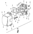
- FIG. 1 is an exploded perspective view of an automated meter reader module as the automated meter reader module would be attached to and a utility meter.
- FIG. 2 is an exploded perspective view of an automated meter reader module according to an embodiment of the present invention.
- FIG. 3 is an exploded perspective view of an automated meter reader module according to an embodiment of the present invention.
- FIG. 4 is a side view of an automated meter reader endpoint having an automated meter reader module according to an embodiment of the present invention.
- FIG. 5 is a front view of an automated meter reader endpoint having an automated meter reader module according to an embodiment of the present invention.
- FIG. 6 is a top view of an automated meter reader endpoint having an automated meter reader module according to an embodiment of the present invention.
- FIG. 7 is an illustration of an index attachment having register dials.
- FIG. 8 is an illustration of an index attachment having register dials.
- FIG. 9 is an illustration of the inter-connected gear mechanisms of an index attachment and a utility meter.
- FIG. 10 is a perspective view of a meter interface mechanism according to an embodiment of the present invention.
- FIG. 11 is a perspective view of a meter interface mechanism according to an embodiment of the present invention.
- FIG. 12 is a cross-sectional side view of a cross section of a meter interface mechanism according to an embodiment of the present invention.
- FIG. 13 is an elevational view of a side of a meter interface mechanism according to an embodiment of the present invention.
- FIG. 14 is a side view of a meter interface mechanism according to an embodiment of the present invention.
- FIG. 15 is an elevational view of a side of a meter interface mechanism according to an embodiment of the present invention.
- FIG. 16 is a perspective view of a meter interface mechanism according to an embodiment of the present invention.
- FIG. 17 is a perspective view of a meter interface mechanism according to an embodiment of the present invention.
- FIG. 18 is a side view of a meter interface mechanism according to an embodiment of the present invention.
- FIG. 19 is an elevational view of a side of a meter interface mechanism according to an embodiment of the present invention.
- FIG. 20 is a cross-sectional side view of a meter interface mechanism according to an embodiment of the present invention.
- FIG. 21 is an elevational view of a meter interface mechanism according to an embodiment of the present invention.
- FIG. 22 is a side view of a meter interface mechanism according to an embodiment of the present invention.
- FIG. 23 is an elevational view of a meter interface mechanism according to an embodiment of the present invention.
- FIG. 24 is a cross-sectional side view of a meter interface mechanism according to an embodiment of the present invention.
- FIG. 25 is an elevational view of a meter interface mechanism according to an embodiment of the present invention.
- FIG. 26 is a perspective view of an automated meter reader module according to an embodiment of the present invention.
- FIG. 27 is a perspective view of an automated meter reader module according to an embodiment of the present invention.
- FIG. 28 is a read view of an automated meter reader module according to an embodiment of the present invention.
- FIG. 29 is a front view of a utility meter reader.
- FIGS. 1-29 The invention can be more readily understood by reference to FIGS. 1-29 and the following description. While the invention is not necessarily limited to such an application, the invention will be better appreciated using a discussion of example embodiments in such a specific context.
- automated meter reader module 40 comprises a housing 42 , a cover 44 , and a patch antenna 46 , in an example embodiment. Referring to FIGS. 1 , and 4 - 6 , automated meter reader module 40 is attached to utility meter 48 on mounting structure 50 at attachment area 52 to form automated meter reader endpoint 54 .
- Housing 42 has a substantially planar base 56 .
- base 56 On the front side of base 56 , as depicted in FIGS. 1-3 , base 56 has a plurality of walls 58 .
- Walls 56 define housing cavity 60 .
- walls 58 may define a plurality of housing cavities 60 .
- walls 58 define at least two housing sub-cavities 60 a , 60 b .
- base 56 and walls 58 can be configured so housing sub-cavities 60 a , 60 b receive printed circuit board 62 and battery 64 .
- Printed circuit board 62 generally comprises patch antenna 46 and electronic circuitry 66 .
- patch antenna 46 is integrated into printed circuit board 62 .
- an antenna may be separate from electronic circuitry 66 .
- patch antenna 46 generally comprises a printed circuit foil pattern with several standard impedance matching components.
- Electronic circuitry 66 generally comprises switch 68 that generates and/or receives an electronic signal corresponding to radio frequency communications transmitted or received by the antenna.
- Print circuit board 62 can be positioned in housing sub-cavity 60 a in any number of ways. In one embodiment, relative to automated meter reader module 40 that is installed on utility meter 48 , printed circuit board 62 is positioned vertically in housing 42 between left-hand mounting post 70 and right-hand mounting post 72 , as depicted in FIGS. 1-3 . In an example embodiment, printed circuit board 62 is vertically oriented such that patch antenna 46 is above electronic circuitry 66 in an installed automated reader meter module 40 . In this embodiment, patch antenna 46 occupies a portion of sub-cavity 60 a that extends beyond the perimeter of attachment area 52 of utility meter 48 , as depicted in FIG. 1 .
- printed circuit board 62 and battery 64 should be fixedly secured within housing cavity 60 . Although in some instances maintenance may require printed circuit board 62 and battery 64 to be removed, it is anticipated that printed circuit board 62 and battery 64 will remain in place for approximately the life of battery 64 , such as, for example, around twenty years. This is typically accomplished by potting or filling one or more housing cavities with a potting material.
- printed circuit board 62 comprises at least one biasing member as depicted in FIGS. 2-3 .
- Biasing member 74 may be any resiliently compressible component attachable to a side of printed circuit board 62 .
- printed circuit board comprises two biasing members 74 having an elongated body and a resiliently compressible annular end distal to the elongated body. The biasing members 74 are typically located near opposite ends of one side of printed circuit board 62 .
- biasing members 74 exert a force against a portion of walls 58 and thereby push printed circuit board 62 against an opposite portion of walls 58 .
- base 42 and walls 58 are generally configured so that biasing members 74 extending from a surface of printed circuit board 62 contact a portion of walls 58 a , 58 b .
- Opposite surface of printed circuit board 62 contacts an opposite portion of walls 58 c , 58 d .
- the opposite portion of walls 58 c , 58 d may comprises an edge or edges that partially extend beyond a plane formed by walls 58 .
- the biasing members 74 provide a mechanism for releasably securing printed circuit board 62 in position during the manufacturing process such that printed circuit board 62 can be conveniently installed and also, if needed, removed and reinstalled, prior to potting the AMR module.
- index attachment can be secured to left-hand and right-hand mounting posts 70 , 72 .
- left-hand and right-hand mounting posts 70 , 72 extending from base 42 are interfaced with index attachment 76 .
- left-hand and right-hand mounting posts 70 , 72 are specifically adapted to interface with index attachment 76 originally mounted to and subsequently removed from utility meter 48 .
- index fastening members 78 are inserted through index attachment 76 and secured to left-hand and right-hand mounting posts 70 , 72 .
- left-hand and right-hand mounting posts 70 , 72 are adapted to receive index fasteners members 78 originally used to secure index attachment 76 to mounting structure 50 of utility meter 48 .
- automated reader module 49 typically utilizes index attachment 76 and index fastening members 78 originally installed on existing utility meter 48 , new index attachment 76 and new index fastening members 78 could easily be attached to left-hand and right-hand mounting posts 70 , 72 during the process of manufacturing and assembling automated meter reader module 40 .
- left-hand and right-hand mounting posts 70 , 72 can be arranged in any number of ways to determine the placement of index attachment 76 in automated reader meter module 40 .
- An attachment 76 having register dials 79 is depicted in FIGS. 7-8 .
- left-hand and right-hand mounting posts 70 , 72 are aligned horizontally on base 56 in relation to an automated meter reader module 40 attached to utility meter 48 , as depicted in FIGS. 1-3 .
- left-hand and right-hand mounting posts 70 , 72 are horizontally aligned near bottom of base 56 such that index attachment 76 is situated below a portion of sub-cavity 60 a that extends beyond the perimeter of attachment area 52 of utility meter 48 .
- patch antenna 46 occupies the portion of sub-cavity 60 a that extends beyond the perimeter of attachment area 52 . In this way, patch antenna 46 extends above index attachment 76 relative to automated meter reader module 40 mounted to mounting structure 50 at attachment area 52 of utility meter 48 . By utilizing patch antenna 46 that extends above index attachment 76 , automated reader module 40 can provide an improved radio frequency transmission pattern and improved reception of radio frequency transmissions.
- the AMR module includes a wriggler 80 is located within wriggler housing 82 .
- Wriggler housing 82 may be separate from or integrated into walls 58 .
- wriggler housing 82 is integrated into walls 58 , as depicted in FIGS. 1-3 .
- wriggler 80 can be brought into closer proximity to switch 68 in electronic circuitry 66 .
- Close proximity between wriggler 80 and printed circuit board 62 is advantageous because wriggler 80 typically wirelessly communicates with switch 68 that translates rotations of a relatively small magnet 84 into electronic signals.
- the functionality of wriggler 80 is further described in U.S. Publication No. 2003/0151886 A1 Buhl, the disclosure of which is hereby incorporated by reference in its entirety.
- the rate at which wriggler 80 rotates is representative of the rate at which a utility such as gas, water, or electricity is consumed.
- consumption of a utility by a consumer causes a gear mechanism in meter drive 86 of utility meter 48 to rotationally engage index gear system 88 in index attachment 76 .
- Meter drive 86 in utility meter 48 has meter interface 90 that rotationally engages index interface 92 of index drive 94 in index attachment 76 .
- index gear system 88 in index interface 76 produce corresponding rotation of visible register dials 79 located on the outward-facing surface 92 of index attachment 76 .
- index attachment 76 When index attachment 76 is removed from utility meter 48 and attached to automated meter reader module 40 , however, meter drive 86 is no longer able to act upon index drive 94 to produce visible rotations of register dials 79 . Therefore, an important additional function of wriggler 80 is to provide an operable interface between meter drive 86 and index drive 94 .
- wriggler 80 comprises label drive shaft 95 , index interface mechanism 96 , and meter interface mechanism 98 .
- Meter interface mechanism 98 is designed to matingly engage meter interface 98 .
- index interface mechanism 98 is designed to matingly engage index interface 98 .
- shaft 94 and index interface mechanism 96 integrally form a separate component from meter interface mechanism 98 .
- Lockable tip 100 on an end of drive shaft 95 distal to index interface mechanism 96 lockably secures meter interface mechanism 98 to drive shaft 94 .
- Wriggler 80 can be operably connected to meter interface 90 and index interface 92 in any order. Since consumption of a utility by a consumer can continue to rotationally drive meter interface 90 during installation, it may be preferable to operably connect wriggler 80 to index attachment 76 before operably connecting wriggler 80 to utility meter 48 . By first attaching wriggler 80 to index attachment 76 , meter drive 86 will not cause index interface 92 to rotate, which can interfere or complicate the installation procedure.
- wriggler 80 can be attached to index attachment 76 in any manner that avoids the mating of a rotationally moving component to a rotationally stationary component, attaching wriggler 80 to utility meter 48 often requires index attachment mechanism 98 to matingly engage meter interface 90 while meter interface 90 is rotating.
- index attachment mechanism 98 to matingly engage meter interface 90 while meter interface 90 is rotating.
- meter drive 86 will cause meter interface 90 to rotate if a consumer continues to use a utility. Since it can be inappropriate, impractical, or uneconomic to temporarily suspend service of a utility during installation, wriggler 80 must be operably connectable to utility meter 48 while meter interface is rotating 90 .
- a meter interface mechanism 98 must be adapted to matingly engage rotating meter interface 90 .
- meter interface mechanism 98 may comprise different shapes and configures, as seen by a comparison of meter interface mechanism 98 , depicted in FIG. 2 and FIG. 3 .
- automated meter reader module 40 has wriggler 80 with meter interface mechanism 98 that facilitates mating engagement with rotating meter interface 90 and reduces the likelihood of binding.
- meter interface mechanism 98 has two spaced-apart interface members 102 extending beyond locking tip 100 along an axis parallel to the axis of drive shaft 94 .
- meter interface mechanism has elongated neck 104 , toothed gear 106 with teeth extending along axes perpendicular the axis of drive shaft 94 .
- FIGS. 10-11 an example embodiment is depicted of meter interface mechanism 98 having two interface members 102 .
- Interface members 102 are spaced approximately one-hundred eighty degrees apart.
- Interface members 102 can matingly engage meter interface 90 while meter interface 90 is rotating.
- Exemplary dimensions of meter interface mechanism 98 with interface members 102 are listed in FIGS. 12-15 .
- One skilled in the art will recognize that changes may be made to the dimensions listed in FIGS. 12-15 , as well as ratios of these dimensions, without departing from the spirit and scope of the present invention.
- meter interface mechanism 98 having toothed gear 106 with beveled teeth 108 .
- Beveled teeth 108 can matingly engage meter interface 90 while meter interface 90 is rotating.
- Beveled teeth 108 allow meter interface mechanism 98 to self-centering into and matingly engage meter interface 90 .
- Meter interface mechanism 98 also has elongated neck 104 .
- Elongated neck 104 can also facilitate operable connection of wriggler 80 to utility meter 48 by permitting an installer to observe whether toothed gear 106 has properly engaged meter interface 90 .
- Exemplary dimensions of meter interface mechanism 98 with beveled teeth 108 and elongated neck 104 are listed in FIGS. 18-25 .
- FIGS. 18-25 Exemplary dimensions of meter interface mechanism 98 with beveled teeth 108 and elongated neck 104 are listed in FIGS. 18-25 .
- FIGS. 18-25 One skilled in the art will recognize that changes may be made to the dimensions listed in FIGS. 18-25 ,
- wriggler 80 interfaces utility meter 48 and index attachment 76 such that consumption of a utility such as gas, electricity, or water causes meter drive 86 to rotate register dials 79 in the following manner: (i) meter drive 86 causes meter interface 90 to rotate; (ii) meter interface 90 causes meter interface mechanism 98 to rotate; (iii) meter interface mechanism 98 causes drive shaft 95 to rotate; (iv) drive shaft 95 causes index interface mechanism 96 to rotate; (v) index interface mechanism 96 causes index interface 92 to rotate; (vi) index interface 92 causes gears of index gear system 88 to rotate; and (vi) index gear system 88 causes register dials 79 to rotate.
- a utility such as gas, electricity, or water
- cover 44 encloses housing 42 , index attachment 76 , printed circuit board 62 , battery 64 , wriggler 80 , and other components.
- cover 44 is secured to mounting structure 50 of utility meter 98 with mounting fastening members 110 .
- housing 42 is positioned between utility meter 48 and cover 44 .
- cover 44 is adapted to receive mounting fastening members 110 originally used to previous endpoint cover to attachment area 52 of utility meter 48 .
- automated reader module 40 typically utilizes mounting fastening members 110 originally installed on existing utility meter 48 , new mounting fastening members 110 could easily be used as well.
- Cover 44 may be made from any number of materials. Generally, cover 44 is made of a transparent polymer. By making cover 44 from a transparent polymer, register dials 79 of index attachment 76 can be read without having to remove cover 44 . Referring to FIGS. 26-27 , cover 44 may have multiple viewing surfaces. Multiple viewing surfaces permit register dials 79 of index attachment 76 to be read from several vantage points. In an example embodiment, register dials 79 can be viewed through at least substantially planar front viewing surface 112 and substantially concave top viewing surface 114 .
- gasket 116 also protects the internal components of automated meter reader module 40 from contamination or interference due to moisture, dust, insects, or other environmental debris. As depicted in FIG. 28 , gasket 116 forms a seal around the perimeter of housing 42 . When automated meter reader module 40 is mounted, gasket 116 substantially seals the interface of mounting structure 56 and housing 42 and the interface of cover 44 and housing 42 .
- cover 44 has mounting apertures 118 through which mounting fastening members 110 can be inserted and fastened to mounting structure 50 .
- mounting apertures 118 are located in outward-extending wings of cover 44 .
- mounting fastening members 110 do not penetrate housing 56 or gasket 116 .
- mounting apertures 118 are located in the corners of housing 56 .
- mounting fastening members 110 are also inserted through gasket 116 .
- gasket 116 provides a compression fit that enhances the effectiveness of the enclosure formed by cover 44 and housing 42 in both of these embodiments.
- gasket 116 may have a raised flange extending beyond the outer-most surface of cover 44 . The extended flange can increase the effectiveness the seal between cover 44 to mounting structure 50 .
- Design features in automated meter reader module 40 can also provide a compression fit between housing 42 and cover 44 .
- outer surfaces of walls 58 contact inner surface of cover 44 .
- the inherent resiliency of the materials from which walls 58 and cover 44 are made causes housing 42 and cover 44 to come into forcible contact, thereby creating a compression fit.
- gasket 116 is made of a Thermoplastic Elastomer (TPE) material, such as, for example, Thermoplastic Vulcanzite (TPV) such as SantopreneTM 211-55.
- TPE Thermoplastic Elastomer
- TPV Thermoplastic Vulcanzite
- FIG. 28 a cork gasket 120 as utilized in the prior art can adhere to the surface of mounting structure 50 , which requires additional time and effort to remove. Cork is also susceptible to deterioration, such as cracking, that can destroy the seal in the interface of mounting structure 50 and housing 42 and the interface of cover 44 and housing 42 .
- Use of polymeric material for gasket 116 improves the durability of automated meter reader module 40 with respect to the use other materials, such as cork, previously used for gasket 116 .
- the use of such a polymeric material for gasket 116 permits a releasable and resealable arrangement that facilitates maintenance of the AMR module and the meter itself without necessitating installation of a new sealing member.
- the use of a polymeric material for gasket 116 can also enhance the compression fit of cover 44 to housing 42 by frictionally securing cover 42 in place.
- Automated meter reader module 40 may comprise several additional features that improve reliability, functionality, and durability of electronic components.
- housing cavity 60 is filled with a potting material. Potting material provides a substantially moisture-impermeable physical barrier between electronic components and environmental contaminants while not substantially adversely affect the performance of electronic components such as electronic circuitry 66 and battery 64 .
- surface of cover 44 may be configured such bottom face 122 having lower outward-facing edges 124 of automated meter reader module does not form a right angle with respect to the plane of attachment area 52 .
- lower-outward-facing edges 122 are oriented outwardly downward such that bottom face 122 is substantially planar and forms an angle with respect to the place of attachment area 52 in a range of about ninety-five degrees to slightly more than ninety degrees.
- bottom face 122 is substantially planar and forms an angle with respect to the place of attachment area 52 in a range of about ninety-one degrees to about ninety-two degrees.
- cover 44 may also be provided with structure defining drainage hole 126 . If water enters automated meter reader module 40 , such as through a crack in gasket 116 , or condensation due to humidity builds up, water or accumulated condensation can exit automated meter reader module 40 into the outside environment by passing through drainage hole 126 .
- the outwardly downward orientation of bottom face 122 of cover 44 of one embodiment can facilitate the formation of an exit path for water through drainage holes 126 .
- Drainage holes 126 can be configured in any number of ways. In an example embodiment, drainage holes 126 are configured to form a small leak path at or near the edge where front surface 112 and bottom surface 122 are joined, such as depicted in FIGS. 2-3 .
- drainage holes 126 are large enough to prevent water tension from impeding the drainage of water or accumulated moister, but small enough to block or substantially deter invasion of automated meter reader module 40 by insects.
- Drainage holes 126 may be located in any portion of cover 44 .
- drainage holes 126 are embedded in the portion of cover 44 in which bottom surface 122 transitions into front surface 112 .
- drainage holes 126 are also spaced apart such that each drainage hole 126 occupies a location at or near a side edge of front surface 112 . In this manner, drainage holes minimize the amount of water or condensation that can build up within automated meter reader module in the event that bottom surface 122 of cover 44 is not level subsequent to installation.
- Drainage hole 126 can be of any size and shape that permits the escape of water or accumulated condensation from automated meter reader module 40 .
- the dimensions and shapes of drainage hole 126 are configured such that insects, such as fire ants, are discouraged from attempting to access the interior of the AMR module 40 .
- drainage hole 126 is substantially slit-like wherein a dimension of drainage hole 126 in one direction is substantially greater than a dimension in another direction. This tends configuration permits fluid substances, such as water, to exit through drainage hole 126 by conforming to the size and shape of the opening while limiting entry of rigid bodies to those conforming to the smallest dimension of drainage hole 126 .
- the location of drainage holes 126 in a portion of cover transitioning from bottom surface 122 into front surface 112 can minimize the size drainage holes 126 while maximizing proximity to bottom surface 122 .
- the effectiveness of drainage holes 126 in discouraging the unintended entry of water and insects can also be enhanced through the addition of various structures on the inside surface of cover 44 .
- Such structures are defined proximate drainage holes 126 to prevent a direct line of access into automated meter reader module 40 through drainage hole 126 .
- These structures may comprise any number of configurations that inhibit access through drainage holes 126 .
- the inside surface of front surface 112 has a ledge, approximately 1.2 mm ⁇ 10.2 mm, located about 2.2 mm above drainage hole, approximately 0.5 mm ⁇ 5 mm in size, to limit a direct penetration into the housing.
- Gasket 116 may also have weeping holes 122 in the portion of gasket 116 interfacing with the side of housing 42 and mounting structure 50 of utility meter 48 .
- Weeping holes 122 can channel water that may enter the space between automated meter reader module 40 and mounting structure 58 , such as accumulated condensation or water that has entered this space through a crack in gasket 116 .
Abstract
Description
Claims (8)
Priority Applications (5)
| Application Number | Priority Date | Filing Date | Title |
|---|---|---|---|
| US11/695,503 US7973673B2 (en) | 2007-04-02 | 2007-04-02 | Automated meter reader direct mount endpoint module |
| CA2628118A CA2628118C (en) | 2007-04-02 | 2008-04-01 | Automated meter reader direct mount endpoint module |
| MX2008004395A MX2008004395A (en) | 2007-04-02 | 2008-04-02 | Automated meter reader direct mount endpoint module. |
| US12/912,270 US20110038104A1 (en) | 2007-04-02 | 2010-10-26 | Automated meter reader direct mount endpoint module |
| MX2011009389A MX2011009389A (en) | 2007-04-02 | 2011-09-07 | Automated meter reader direct mount endpoint module. |
Applications Claiming Priority (1)
| Application Number | Priority Date | Filing Date | Title |
|---|---|---|---|
| US11/695,503 US7973673B2 (en) | 2007-04-02 | 2007-04-02 | Automated meter reader direct mount endpoint module |
Related Child Applications (1)
| Application Number | Title | Priority Date | Filing Date |
|---|---|---|---|
| US12/912,270 Division US20110038104A1 (en) | 2007-04-02 | 2010-10-26 | Automated meter reader direct mount endpoint module |
Publications (2)
| Publication Number | Publication Date |
|---|---|
| US20080238711A1 US20080238711A1 (en) | 2008-10-02 |
| US7973673B2 true US7973673B2 (en) | 2011-07-05 |
Family
ID=39793344
Family Applications (2)
| Application Number | Title | Priority Date | Filing Date |
|---|---|---|---|
| US11/695,503 Active 2030-05-04 US7973673B2 (en) | 2007-04-02 | 2007-04-02 | Automated meter reader direct mount endpoint module |
| US12/912,270 Abandoned US20110038104A1 (en) | 2007-04-02 | 2010-10-26 | Automated meter reader direct mount endpoint module |
Family Applications After (1)
| Application Number | Title | Priority Date | Filing Date |
|---|---|---|---|
| US12/912,270 Abandoned US20110038104A1 (en) | 2007-04-02 | 2010-10-26 | Automated meter reader direct mount endpoint module |
Country Status (3)
| Country | Link |
|---|---|
| US (2) | US7973673B2 (en) |
| CA (1) | CA2628118C (en) |
| MX (2) | MX2008004395A (en) |
Cited By (6)
| Publication number | Priority date | Publication date | Assignee | Title |
|---|---|---|---|---|
| US20110254696A1 (en) * | 2010-04-14 | 2011-10-20 | Itron, Inc. | Meter right sizing |
| US8462060B2 (en) * | 2001-11-26 | 2013-06-11 | Itron, Inc. | Embedded antenna apparatus for utility metering applications |
| US8842712B2 (en) | 2011-03-24 | 2014-09-23 | Gregory C. Hancock | Methods and apparatuses for reception of frequency-hopping spread spectrum radio transmissions |
| US20150015414A1 (en) * | 2013-07-11 | 2015-01-15 | Honeywell International Inc. | Magnetically-impervious retrofit kit for a metered-commodity consumption meter |
| US9285243B2 (en) | 2009-03-27 | 2016-03-15 | The Research Foundation For The State University Of New York | Automated meter reading system and energy conservation method using same |
| US11201395B2 (en) | 2019-09-09 | 2021-12-14 | Honeywell International Inc. | Camouflaged single branch dual band antenna for use with power meter |
Families Citing this family (19)
| Publication number | Priority date | Publication date | Assignee | Title |
|---|---|---|---|---|
| EP2299247B2 (en) * | 2009-09-14 | 2022-08-31 | Itron GmbH | Electronic module for a gas meter |
| CA3177996A1 (en) | 2010-06-16 | 2011-12-22 | Mueller International, Llc | Infrastructure monitoring devices, systems, and methods |
| DK2609398T3 (en) * | 2010-08-27 | 2014-09-08 | Northq Aps | A retrofitted system for automatically reading consumption meters and a template for aligning the housing of an optical sensor therein. |
| US9593999B2 (en) | 2011-08-12 | 2017-03-14 | Mueller International, Llc | Enclosure for leak detector |
| ITTA20120003A1 (en) * | 2012-02-14 | 2013-08-15 | Martino Convertini | HIGH SENSITIVITY DIRECT READING DEVICE FOR GAS METERS |
| USD737822S1 (en) * | 2014-03-10 | 2015-09-01 | Datalogic Ip Tech S.R.L. | Optical module |
| DE102014016714A1 (en) * | 2014-11-13 | 2016-05-19 | Rwe Effizienz Gmbh | Method and device for the electronic detection of an instantaneous power on a mechanical counter |
| US10305178B2 (en) | 2016-02-12 | 2019-05-28 | Mueller International, Llc | Nozzle cap multi-band antenna assembly |
| US10283857B2 (en) | 2016-02-12 | 2019-05-07 | Mueller International, Llc | Nozzle cap multi-band antenna assembly |
| EP3239666A1 (en) * | 2016-04-27 | 2017-11-01 | PLUM spólka z ograniczona odpowiedzialnoscia | An electronic readout assembly for a flow meter |
| US10164320B1 (en) * | 2017-08-08 | 2018-12-25 | Badger Meter, Inc. | System and method for sealing potting material from an antenna cavity |
| CN108169618B (en) * | 2018-01-08 | 2021-02-09 | 四川九洲电器集团有限责任公司 | Testing device and testing method |
| WO2019143630A1 (en) * | 2018-01-16 | 2019-07-25 | Pacific Gas And Electric Company | Multi-purpose (multi-dwelling) electric metering system and method |
| US10859462B2 (en) | 2018-09-04 | 2020-12-08 | Mueller International, Llc | Hydrant cap leak detector with oriented sensor |
| US11342656B2 (en) * | 2018-12-28 | 2022-05-24 | Mueller International, Llc | Nozzle cap encapsulated antenna system |
| EP3739346B1 (en) * | 2019-05-14 | 2023-07-12 | Landis+Gyr AG | Load control module for a utility meter and meter arrangement comprising same |
| US11473993B2 (en) | 2019-05-31 | 2022-10-18 | Mueller International, Llc | Hydrant nozzle cap |
| WO2021212128A1 (en) * | 2020-04-14 | 2021-10-21 | Nicor, Inc. | Modular ami/amr in-ground meter box |
| US11542690B2 (en) | 2020-05-14 | 2023-01-03 | Mueller International, Llc | Hydrant nozzle cap adapter |
Citations (69)
| Publication number | Priority date | Publication date | Assignee | Title |
|---|---|---|---|---|
| US3425275A (en) | 1967-04-03 | 1969-02-04 | Ripley Co Inc | Auxiliary metering apparatus |
| US3793563A (en) | 1972-11-08 | 1974-02-19 | Analog Devices Inc | Case for panel-mounted electrical instruments |
| US3893586A (en) | 1974-05-10 | 1975-07-08 | Neptune Int Corp | Tamper-proof case for meter or register |
| US3909908A (en) | 1972-11-08 | 1975-10-07 | Analog Devices Inc | Method for making cases for panel-mounted electrical instruments |
| US3931992A (en) | 1973-11-30 | 1976-01-13 | Badger Meter, Inc. | Universal joint connector |
| US4092698A (en) | 1976-09-16 | 1978-05-30 | Analog Devices, Incorporated | Protective case for electrical instruments on circuit boards |
| US4463354A (en) | 1981-12-09 | 1984-07-31 | Sears Lawrence M | Apparatus for communicating utility usage related information from a utility usage location to a portable utility usage registering device |
| US4640985A (en) | 1985-04-26 | 1987-02-03 | Schlumberger Canada Limited | Snap-fitting transformer terminal cover |
| US4786903A (en) | 1986-04-15 | 1988-11-22 | E. F. Johnson Company | Remotely interrogated transponder |
| US4811600A (en) | 1986-04-21 | 1989-03-14 | Sappel | Device for making flowmeter tamperproof |
| US4851803A (en) | 1988-07-25 | 1989-07-25 | E-Mon Corporation | Split core insulator and locking device |
| US4859944A (en) | 1987-08-25 | 1989-08-22 | Analog Devices, Inc. | Single-winding magnetometer with oscillator duty cycle measurement |
| US4977368A (en) | 1988-04-26 | 1990-12-11 | Abb Power T&D Company | Electric utility meter with electronic register |
| US5001420A (en) | 1989-09-25 | 1991-03-19 | General Electric Company | Modular construction for electronic energy meter |
| US5027056A (en) | 1990-04-05 | 1991-06-25 | General Electric Company | Multifunction register enclosure for energy meter |
| US5027061A (en) | 1989-09-25 | 1991-06-25 | General Electric Company | Electromagnetic and thermal shield for electronic energy meter |
| US5049810A (en) | 1989-09-22 | 1991-09-17 | Landis & Gyr Metering, Inc. | Watt-hour meter cover with battery hatch reset switch and optical communication port |
| US5057767A (en) | 1990-04-05 | 1991-10-15 | General Electric Company | Optical communications light shield for energy meter |
| US5066906A (en) | 1989-09-22 | 1991-11-19 | Landis & Gyr Metering, Inc. | Time of use register for use with a utility meter |
| US5088004A (en) | 1991-05-31 | 1992-02-11 | Schlumberger Canada, Ltd. | Electricity metering device with cover |
| US5107203A (en) | 1990-11-26 | 1992-04-21 | Schlumberger Industries Inc. | Sealed utility meter having internal automatic disconnection |
| US5120252A (en) | 1990-04-05 | 1992-06-09 | General Electric Company | Method of mounting disk sensing optics onto circuit board of watthour meter |
| US5134544A (en) | 1991-05-31 | 1992-07-28 | Schlumberger Canada, Ltd. | Cable retaining mechanism for an electricity metering device |
| US5181166A (en) | 1991-05-31 | 1993-01-19 | Schlumberger Canada Limited | Securing mechanism for an electricity metering device |
| US5196783A (en) | 1991-05-31 | 1993-03-23 | Schlumberger Canada, Ltd. | Vent for electricity metering device |
| US5270639A (en) | 1989-09-22 | 1993-12-14 | Landis & Gyr Metering, Inc. | Time of use register for use with a utility meter |
| US5339686A (en) | 1993-02-03 | 1994-08-23 | Badger Meter, Inc. | Water meter housing connection apparatus |
| US5343143A (en) | 1992-02-11 | 1994-08-30 | Landis & Gyr Metering, Inc. | Shielded current sensing device for a watthour meter |
| US5364290A (en) | 1992-03-20 | 1994-11-15 | Schlumberger Canada Limited | Electric utility revenue meter polycarbonate base |
| US5416475A (en) | 1993-07-23 | 1995-05-16 | Schlumberger Industries, Inc. | Remote meter reading receptacle for pit lid mounting |
| US5421201A (en) | 1994-06-27 | 1995-06-06 | Pellerin, Jr.; William J. | Adapter for connecting an encoder remote transmitter to a gas meter |
| US5473504A (en) | 1994-12-27 | 1995-12-05 | General Electric Company | Electric meter with desired seating torque |
| US5486755A (en) | 1994-12-27 | 1996-01-23 | General Electric Company | Electronic meter having anti-tampering magnetic shield |
| US5495239A (en) | 1994-08-02 | 1996-02-27 | General Electric Company | Method and apparatus for communicating with a plurality of electrical metering devices and a system control center with a mobile node |
| US5514959A (en) | 1994-12-27 | 1996-05-07 | General Electric Company | Electric meter including a switch cover lockable in an open position |
| US5564470A (en) | 1993-07-27 | 1996-10-15 | Btr Plc | Valve assembly |
| US5767790A (en) | 1996-03-07 | 1998-06-16 | Jovellana; Bartolome D. | Automatic utility meter monitor |
| US5777222A (en) | 1997-04-10 | 1998-07-07 | Ugi Meters Limited | Fluid meter with modular automatic meter reading unit |
| US5825303A (en) | 1996-08-30 | 1998-10-20 | Badger Meter, Inc. | Sealed housing and method of sealing for apparatus in meter pit enclosures |
| US5926014A (en) | 1997-03-17 | 1999-07-20 | General Electric Company | Magnetic shield for plastic molded electricity meter frames |
| US6054780A (en) | 1997-10-23 | 2000-04-25 | Analog Devices, Inc. | Magnetically coupled signal isolator using a Faraday shielded MR or GMR receiving element |
| US6084395A (en) | 1998-06-24 | 2000-07-04 | Abb Power T&D Company Inc. | Stackable plastic cover for use on electrical meters |
| US6100817A (en) | 1998-03-17 | 2000-08-08 | Abb Power T&D Company Inc. | Fixed network RF communications complaint with CEBus protocol |
| US6100816A (en) | 1998-01-16 | 2000-08-08 | Cellnet Data Systems, Inc. | Utility meter adapter |
| US6111519A (en) | 1997-08-12 | 2000-08-29 | Badger Meter, Inc. | Battery assembly |
| US6162082A (en) | 1999-01-28 | 2000-12-19 | Badger Meter, Inc. | Submersible electrical connector and method for quick connection and disconnection including tamper indication |
| US6177884B1 (en) | 1998-11-12 | 2001-01-23 | Hunt Technologies, Inc. | Integrated power line metering and communication method and apparatus |
| US6218995B1 (en) | 1997-06-13 | 2001-04-17 | Itron, Inc. | Telemetry antenna system |
| US6411219B1 (en) | 1999-12-29 | 2002-06-25 | Siemens Power Transmission And Distribution, Inc. | Adaptive radio communication for a utility meter |
| US6414605B1 (en) | 1998-09-02 | 2002-07-02 | Schlumberger Resource Management Services, Inc. | Utility meter pit lid mounted antenna assembly and method |
| US6426027B1 (en) | 2000-05-17 | 2002-07-30 | Neptune Technology Group, Inc. | Method of injection molding for creating a fluid meter housing |
| US20020163442A1 (en) | 2001-05-02 | 2002-11-07 | Invensys Metering Systems/North America Inc. | Automatic meter reading module |
| US20020193144A1 (en) | 2001-05-04 | 2002-12-19 | Invensys Metering Systems-North America Inc. | System and method for communicating and control of automated meter reading |
| US6522124B1 (en) | 2000-11-01 | 2003-02-18 | Schlumberger Resource Management Services, Inc. | Snap connecting inner modules for an electric utility meter |
| US6528986B2 (en) | 2000-12-28 | 2003-03-04 | Schlumberger Resource Management Services, Inc. | Inner component board assembly for an electric utility meter |
| US20030089298A1 (en) | 2001-11-15 | 2003-05-15 | Erwin Holowick | Dual magnetic register for a utility meter |
| US20030151886A1 (en) | 2002-02-12 | 2003-08-14 | Kim Buhl | System and method for retrofitting utility meter reading modules |
| US6756914B1 (en) | 1999-11-12 | 2004-06-29 | Itron, Inc. | Low impedance encoder for a utility meter |
| US6773652B2 (en) | 2002-10-02 | 2004-08-10 | Elster Electricity, Llc | Process for the manufacture of a cover system for an electrical-energy meter |
| US6797884B2 (en) | 2002-11-12 | 2004-09-28 | Yazaki Corporation | Waterproof cover structure of electric distribution box |
| WO2004085973A2 (en) | 2003-03-25 | 2004-10-07 | Invensys Metering Systems Gmbh Ludwigshafen | Water-meter fittings |
| US6816360B2 (en) | 1997-08-15 | 2004-11-09 | General Electric Company | Reduced cost automatic meter reading system and method using locally communicating utility meters |
| US6885185B1 (en) | 1998-12-01 | 2005-04-26 | Itron Electricity Metering, Inc. | Modular meter configuration and methodology |
| US6891104B2 (en) | 2003-01-28 | 2005-05-10 | Thomas & Betts International, Inc. | Hinged weatherproof electrical box cover |
| US6903699B2 (en) | 1998-03-17 | 2005-06-07 | Transdata, Inc. | Wireless communication device for electric meter and method of manufacture thereof |
| US7033193B2 (en) | 2003-12-09 | 2006-04-25 | Higgins Sidney A | Multi-environment in-line connector |
| US7059200B2 (en) | 2004-10-20 | 2006-06-13 | Dresser, Inc. | Flow measurement system and method |
| US20060218104A1 (en) | 2005-03-24 | 2006-09-28 | Johnson Rex A | Method and apparatus for coupling a meter register to an automatic meter reading communication device |
| US7283063B2 (en) | 2005-07-07 | 2007-10-16 | Mars Company | Above ground antenna and transmitter for utility meters |
Family Cites Families (42)
| Publication number | Priority date | Publication date | Assignee | Title |
|---|---|---|---|---|
| US2030094A (en) * | 1934-09-13 | 1936-02-11 | Westinghouse Electric & Mfg Co | Meter mounting |
| US2926014A (en) * | 1956-02-17 | 1960-02-23 | Leesona Corp | Sheet supplying apparatus for coil winding machines |
| US4163939A (en) * | 1978-02-06 | 1979-08-07 | Westinghouse Electric Corp. | Anti-static plastic enclosure for electric utility meters |
| US4315248A (en) * | 1980-02-21 | 1982-02-09 | Energy Optics, Inc. | Load control system for standard electric utility meter |
| US4654662A (en) * | 1984-07-23 | 1987-03-31 | James Van Orsdel | Apparatus for telemetry apparatus for reading utility meters |
| US4614945A (en) * | 1985-02-20 | 1986-09-30 | Diversified Energies, Inc. | Automatic/remote RF instrument reading method and apparatus |
| US4804957A (en) * | 1985-11-27 | 1989-02-14 | Triad Communications, Inc. | Utility meter and submetering system |
| US4904995A (en) * | 1986-01-21 | 1990-02-27 | Emerson Electric Co. | Integrated remote electricity meter transponder and combination |
| US4833618A (en) * | 1986-02-20 | 1989-05-23 | Net Laboratories, Inc. | System for automatically reading utility meters from a remote location |
| US4737797A (en) * | 1986-06-26 | 1988-04-12 | Motorola, Inc. | Microstrip balun-antenna apparatus |
| US5014213A (en) * | 1988-04-20 | 1991-05-07 | Domestic Automation Company, Inc. | System for use with polyphase utility meters for recording time of energy use |
| JP2621120B2 (en) * | 1988-10-19 | 1997-06-18 | 三信工業株式会社 | Fuel supply device for internal combustion engine |
| US5673252A (en) * | 1990-02-15 | 1997-09-30 | Itron, Inc. | Communications protocol for remote data generating stations |
| US5056107A (en) * | 1990-02-15 | 1991-10-08 | Iris Systems Inc. | Radio communication network for remote data generating stations |
| US5553094A (en) * | 1990-02-15 | 1996-09-03 | Iris Systems, Inc. | Radio communication network for remote data generating stations |
| US5546444A (en) * | 1994-03-11 | 1996-08-13 | Bellsouth Corporation | Methods and apparatus for communicating data via a cellular network control channel |
| GB9312836D0 (en) * | 1993-06-22 | 1993-08-04 | Schlumberger Ind Ltd | Multipoint to point radiocommunications network |
| US5451938A (en) * | 1993-10-22 | 1995-09-19 | Schlumberger Industries, Inc. | RF meter reading system |
| US5493287A (en) * | 1994-03-07 | 1996-02-20 | Motorola, Inc. | Method of remotely reading a group of meters |
| US5481259A (en) * | 1994-05-02 | 1996-01-02 | Motorola, Inc. | Method for reading a plurality of remote meters |
| GB9410557D0 (en) * | 1994-05-26 | 1994-07-13 | Schlumberger Ind Ltd | Radio antennae |
| US5602744A (en) * | 1994-09-29 | 1997-02-11 | Meek; Jean L. | Universal send/receive utility usage data gathering system |
| US5541589A (en) * | 1994-12-15 | 1996-07-30 | Delaney; Patrick J. | Power meter data acquisition and control system |
| US5659300A (en) * | 1995-01-30 | 1997-08-19 | Innovatec Corporation | Meter for measuring volumetric consumption of a commodity |
| US5896097A (en) * | 1996-03-06 | 1999-04-20 | Schlumberger Resource Management Services, Inc. | System for utility meter communications using a single RF frequency |
| US5684472A (en) * | 1996-05-08 | 1997-11-04 | Motorola, Inc. | Method and apparatus for remotely accessing meter status information in a meter reading system |
| US5801643A (en) * | 1996-06-20 | 1998-09-01 | Northrop Grumman Corporation | Remote utility meter reading system |
| US6246677B1 (en) * | 1996-09-06 | 2001-06-12 | Innovatec Communications, Llc | Automatic meter reading data communication system |
| US6078785A (en) * | 1996-10-15 | 2000-06-20 | Bush; E. William | Demand reporting of electricity consumption by radio in relays to a base station, and demand relays wattmeters so reporting over a wide area |
| US5847683A (en) * | 1996-10-28 | 1998-12-08 | Motorola, Inc. | Transmission line antenna and utility meter using same |
| US5883886A (en) * | 1997-01-03 | 1999-03-16 | Motorola, Inc. | Utility meter readings on a reverse channel of a two-way paging system |
| US6088659A (en) * | 1997-09-11 | 2000-07-11 | Abb Power T&D Company Inc. | Automated meter reading system |
| US5986574A (en) * | 1997-10-16 | 1999-11-16 | Peco Energy Company | System and method for communication between remote locations |
| US5949383A (en) * | 1997-10-20 | 1999-09-07 | Ericsson Inc. | Compact antenna structures including baluns |
| US5966010A (en) * | 1998-02-09 | 1999-10-12 | Abb Power T&D Company Inc. | Electrical energy meter with snap fit interlocking parts |
| US6181294B1 (en) * | 1998-03-17 | 2001-01-30 | Transdata, Inc. | Antenna for electric meter and method of manufacture thereof |
| US6067052A (en) * | 1998-09-18 | 2000-05-23 | Lucent Technologies Inc. | Loop antenna configuration for printed wire board applications |
| US6453757B1 (en) * | 1999-05-06 | 2002-09-24 | M&Fc Holding Company | Symmetrical ultrasound gas flow meter housing and related multi-configuration gas flow meter assembly |
| US6918311B2 (en) * | 2000-09-22 | 2005-07-19 | M&Fc Holding, Llc | Weather resistant automatic meter reading unit |
| US7154938B2 (en) * | 2002-12-31 | 2006-12-26 | Itron, Inc. | RF communications system utilizing digital modulation to transmit and receive data |
| US7117737B2 (en) * | 2004-05-06 | 2006-10-10 | Dresser, Inc. | Sealed index cover for meter |
| US7453373B2 (en) * | 2004-10-29 | 2008-11-18 | Itron, Inc. | Integrated meter module and utility metering system |
-
2007
- 2007-04-02 US US11/695,503 patent/US7973673B2/en active Active
-
2008
- 2008-04-01 CA CA2628118A patent/CA2628118C/en active Active
- 2008-04-02 MX MX2008004395A patent/MX2008004395A/en active IP Right Grant
-
2010
- 2010-10-26 US US12/912,270 patent/US20110038104A1/en not_active Abandoned
-
2011
- 2011-09-07 MX MX2011009389A patent/MX2011009389A/en unknown
Patent Citations (72)
| Publication number | Priority date | Publication date | Assignee | Title |
|---|---|---|---|---|
| US3425275A (en) | 1967-04-03 | 1969-02-04 | Ripley Co Inc | Auxiliary metering apparatus |
| US3793563A (en) | 1972-11-08 | 1974-02-19 | Analog Devices Inc | Case for panel-mounted electrical instruments |
| US3909908A (en) | 1972-11-08 | 1975-10-07 | Analog Devices Inc | Method for making cases for panel-mounted electrical instruments |
| US3931992A (en) | 1973-11-30 | 1976-01-13 | Badger Meter, Inc. | Universal joint connector |
| US3893586A (en) | 1974-05-10 | 1975-07-08 | Neptune Int Corp | Tamper-proof case for meter or register |
| US4092698A (en) | 1976-09-16 | 1978-05-30 | Analog Devices, Incorporated | Protective case for electrical instruments on circuit boards |
| US4463354A (en) | 1981-12-09 | 1984-07-31 | Sears Lawrence M | Apparatus for communicating utility usage related information from a utility usage location to a portable utility usage registering device |
| US4640985A (en) | 1985-04-26 | 1987-02-03 | Schlumberger Canada Limited | Snap-fitting transformer terminal cover |
| US4786903A (en) | 1986-04-15 | 1988-11-22 | E. F. Johnson Company | Remotely interrogated transponder |
| US4811600A (en) | 1986-04-21 | 1989-03-14 | Sappel | Device for making flowmeter tamperproof |
| US4859944A (en) | 1987-08-25 | 1989-08-22 | Analog Devices, Inc. | Single-winding magnetometer with oscillator duty cycle measurement |
| US4977368A (en) | 1988-04-26 | 1990-12-11 | Abb Power T&D Company | Electric utility meter with electronic register |
| US4851803A (en) | 1988-07-25 | 1989-07-25 | E-Mon Corporation | Split core insulator and locking device |
| US5066906A (en) | 1989-09-22 | 1991-11-19 | Landis & Gyr Metering, Inc. | Time of use register for use with a utility meter |
| US5049810A (en) | 1989-09-22 | 1991-09-17 | Landis & Gyr Metering, Inc. | Watt-hour meter cover with battery hatch reset switch and optical communication port |
| US5270639A (en) | 1989-09-22 | 1993-12-14 | Landis & Gyr Metering, Inc. | Time of use register for use with a utility meter |
| US5027061A (en) | 1989-09-25 | 1991-06-25 | General Electric Company | Electromagnetic and thermal shield for electronic energy meter |
| US5001420A (en) | 1989-09-25 | 1991-03-19 | General Electric Company | Modular construction for electronic energy meter |
| US5027056A (en) | 1990-04-05 | 1991-06-25 | General Electric Company | Multifunction register enclosure for energy meter |
| US5057767A (en) | 1990-04-05 | 1991-10-15 | General Electric Company | Optical communications light shield for energy meter |
| US5120252A (en) | 1990-04-05 | 1992-06-09 | General Electric Company | Method of mounting disk sensing optics onto circuit board of watthour meter |
| US5107203A (en) | 1990-11-26 | 1992-04-21 | Schlumberger Industries Inc. | Sealed utility meter having internal automatic disconnection |
| US5196783A (en) | 1991-05-31 | 1993-03-23 | Schlumberger Canada, Ltd. | Vent for electricity metering device |
| US5181166A (en) | 1991-05-31 | 1993-01-19 | Schlumberger Canada Limited | Securing mechanism for an electricity metering device |
| US5134544A (en) | 1991-05-31 | 1992-07-28 | Schlumberger Canada, Ltd. | Cable retaining mechanism for an electricity metering device |
| US5088004A (en) | 1991-05-31 | 1992-02-11 | Schlumberger Canada, Ltd. | Electricity metering device with cover |
| US5343143A (en) | 1992-02-11 | 1994-08-30 | Landis & Gyr Metering, Inc. | Shielded current sensing device for a watthour meter |
| US5364290A (en) | 1992-03-20 | 1994-11-15 | Schlumberger Canada Limited | Electric utility revenue meter polycarbonate base |
| US5339686A (en) | 1993-02-03 | 1994-08-23 | Badger Meter, Inc. | Water meter housing connection apparatus |
| US5416475A (en) | 1993-07-23 | 1995-05-16 | Schlumberger Industries, Inc. | Remote meter reading receptacle for pit lid mounting |
| US5564470A (en) | 1993-07-27 | 1996-10-15 | Btr Plc | Valve assembly |
| US5421201A (en) | 1994-06-27 | 1995-06-06 | Pellerin, Jr.; William J. | Adapter for connecting an encoder remote transmitter to a gas meter |
| US5495239A (en) | 1994-08-02 | 1996-02-27 | General Electric Company | Method and apparatus for communicating with a plurality of electrical metering devices and a system control center with a mobile node |
| US5473504A (en) | 1994-12-27 | 1995-12-05 | General Electric Company | Electric meter with desired seating torque |
| US5486755A (en) | 1994-12-27 | 1996-01-23 | General Electric Company | Electronic meter having anti-tampering magnetic shield |
| US5514959A (en) | 1994-12-27 | 1996-05-07 | General Electric Company | Electric meter including a switch cover lockable in an open position |
| US5767790A (en) | 1996-03-07 | 1998-06-16 | Jovellana; Bartolome D. | Automatic utility meter monitor |
| US5825303A (en) | 1996-08-30 | 1998-10-20 | Badger Meter, Inc. | Sealed housing and method of sealing for apparatus in meter pit enclosures |
| US5926014A (en) | 1997-03-17 | 1999-07-20 | General Electric Company | Magnetic shield for plastic molded electricity meter frames |
| US5777222A (en) | 1997-04-10 | 1998-07-07 | Ugi Meters Limited | Fluid meter with modular automatic meter reading unit |
| US6218995B1 (en) | 1997-06-13 | 2001-04-17 | Itron, Inc. | Telemetry antenna system |
| USRE38348E1 (en) | 1997-08-12 | 2003-12-16 | Badger Meter, Inc. | Battery assembly |
| US6111519A (en) | 1997-08-12 | 2000-08-29 | Badger Meter, Inc. | Battery assembly |
| US6816360B2 (en) | 1997-08-15 | 2004-11-09 | General Electric Company | Reduced cost automatic meter reading system and method using locally communicating utility meters |
| US6054780A (en) | 1997-10-23 | 2000-04-25 | Analog Devices, Inc. | Magnetically coupled signal isolator using a Faraday shielded MR or GMR receiving element |
| US6100816A (en) | 1998-01-16 | 2000-08-08 | Cellnet Data Systems, Inc. | Utility meter adapter |
| US6100817A (en) | 1998-03-17 | 2000-08-08 | Abb Power T&D Company Inc. | Fixed network RF communications complaint with CEBus protocol |
| US6903699B2 (en) | 1998-03-17 | 2005-06-07 | Transdata, Inc. | Wireless communication device for electric meter and method of manufacture thereof |
| US6084395A (en) | 1998-06-24 | 2000-07-04 | Abb Power T&D Company Inc. | Stackable plastic cover for use on electrical meters |
| US6414605B1 (en) | 1998-09-02 | 2002-07-02 | Schlumberger Resource Management Services, Inc. | Utility meter pit lid mounted antenna assembly and method |
| US6617976B2 (en) | 1998-09-02 | 2003-09-09 | Neptune Technology Group, Inc. | Utility meter pit lid mounted antenna antenna assembly and method |
| US6177884B1 (en) | 1998-11-12 | 2001-01-23 | Hunt Technologies, Inc. | Integrated power line metering and communication method and apparatus |
| US6885185B1 (en) | 1998-12-01 | 2005-04-26 | Itron Electricity Metering, Inc. | Modular meter configuration and methodology |
| US6162082A (en) | 1999-01-28 | 2000-12-19 | Badger Meter, Inc. | Submersible electrical connector and method for quick connection and disconnection including tamper indication |
| US6756914B1 (en) | 1999-11-12 | 2004-06-29 | Itron, Inc. | Low impedance encoder for a utility meter |
| US6411219B1 (en) | 1999-12-29 | 2002-06-25 | Siemens Power Transmission And Distribution, Inc. | Adaptive radio communication for a utility meter |
| US6426027B1 (en) | 2000-05-17 | 2002-07-30 | Neptune Technology Group, Inc. | Method of injection molding for creating a fluid meter housing |
| US6522124B1 (en) | 2000-11-01 | 2003-02-18 | Schlumberger Resource Management Services, Inc. | Snap connecting inner modules for an electric utility meter |
| US6528986B2 (en) | 2000-12-28 | 2003-03-04 | Schlumberger Resource Management Services, Inc. | Inner component board assembly for an electric utility meter |
| US6982651B2 (en) * | 2001-05-02 | 2006-01-03 | M & Fc Holding, Llc | Automatic meter reading module |
| US20020163442A1 (en) | 2001-05-02 | 2002-11-07 | Invensys Metering Systems/North America Inc. | Automatic meter reading module |
| US20020193144A1 (en) | 2001-05-04 | 2002-12-19 | Invensys Metering Systems-North America Inc. | System and method for communicating and control of automated meter reading |
| US20030089298A1 (en) | 2001-11-15 | 2003-05-15 | Erwin Holowick | Dual magnetic register for a utility meter |
| US20030151886A1 (en) | 2002-02-12 | 2003-08-14 | Kim Buhl | System and method for retrofitting utility meter reading modules |
| US6773652B2 (en) | 2002-10-02 | 2004-08-10 | Elster Electricity, Llc | Process for the manufacture of a cover system for an electrical-energy meter |
| US6797884B2 (en) | 2002-11-12 | 2004-09-28 | Yazaki Corporation | Waterproof cover structure of electric distribution box |
| US6891104B2 (en) | 2003-01-28 | 2005-05-10 | Thomas & Betts International, Inc. | Hinged weatherproof electrical box cover |
| WO2004085973A2 (en) | 2003-03-25 | 2004-10-07 | Invensys Metering Systems Gmbh Ludwigshafen | Water-meter fittings |
| US7033193B2 (en) | 2003-12-09 | 2006-04-25 | Higgins Sidney A | Multi-environment in-line connector |
| US7059200B2 (en) | 2004-10-20 | 2006-06-13 | Dresser, Inc. | Flow measurement system and method |
| US20060218104A1 (en) | 2005-03-24 | 2006-09-28 | Johnson Rex A | Method and apparatus for coupling a meter register to an automatic meter reading communication device |
| US7283063B2 (en) | 2005-07-07 | 2007-10-16 | Mars Company | Above ground antenna and transmitter for utility meters |
Non-Patent Citations (2)
| Title |
|---|
| Arun Sehgal; AMR Offers Multiple Benefits; PipeLine and Gas Technology; Apr./May 2005; © Hart Energy Publishing; (3 pages). |
| Itron; 40GB ERT Module; Funtionality Profile; Oct. 2006; (4 pages). |
Cited By (8)
| Publication number | Priority date | Publication date | Assignee | Title |
|---|---|---|---|---|
| US8462060B2 (en) * | 2001-11-26 | 2013-06-11 | Itron, Inc. | Embedded antenna apparatus for utility metering applications |
| US9285243B2 (en) | 2009-03-27 | 2016-03-15 | The Research Foundation For The State University Of New York | Automated meter reading system and energy conservation method using same |
| US20110254696A1 (en) * | 2010-04-14 | 2011-10-20 | Itron, Inc. | Meter right sizing |
| US8269650B2 (en) * | 2010-04-14 | 2012-09-18 | Itron, Inc. | Meter right sizing |
| US8842712B2 (en) | 2011-03-24 | 2014-09-23 | Gregory C. Hancock | Methods and apparatuses for reception of frequency-hopping spread spectrum radio transmissions |
| US20150015414A1 (en) * | 2013-07-11 | 2015-01-15 | Honeywell International Inc. | Magnetically-impervious retrofit kit for a metered-commodity consumption meter |
| US9109922B2 (en) * | 2013-07-11 | 2015-08-18 | Honeywell International Inc. | Magnetically-impervious retrofit kit for a metered-commodity consumption meter |
| US11201395B2 (en) | 2019-09-09 | 2021-12-14 | Honeywell International Inc. | Camouflaged single branch dual band antenna for use with power meter |
Also Published As
| Publication number | Publication date |
|---|---|
| MX2008004395A (en) | 2009-02-27 |
| US20080238711A1 (en) | 2008-10-02 |
| US20110038104A1 (en) | 2011-02-17 |
| CA2628118C (en) | 2016-03-22 |
| MX2011009389A (en) | 2011-10-05 |
| CA2628118A1 (en) | 2008-10-02 |
Similar Documents
| Publication | Publication Date | Title |
|---|---|---|
| US7973673B2 (en) | Automated meter reader direct mount endpoint module | |
| EP1393022B1 (en) | Add-on module for utility meters | |
| US7290456B2 (en) | Flow measurement system and method | |
| US6100816A (en) | Utility meter adapter | |
| US10330507B2 (en) | Meter register and utility meter having wireless remote reading arrangement | |
| AU2002308535A1 (en) | Automatic meter reading module | |
| EP1875171B1 (en) | System and method for transmitting consumption measurement data from a utility meter to a remote monitoring location | |
| US4998102A (en) | Integrated meter transponder | |
| CA2791128C (en) | An electronic meter register having a bottom formed by sealing material and a method of manufacture thereof | |
| US20140361908A1 (en) | Wireless utility metering devices, systems, and methods | |
| CA2748721A1 (en) | An antenna attachment scheme for mounting an antenna to a meter | |
| BR102018069869B1 (en) | LIQUID GAS LEVEL MEASUREMENT SYSTEM | |
| US20110248169A1 (en) | Light Activated Configuration of Environmentally Sealed Metering Products | |
| CN219499777U (en) | Control box | |
| RU150626U1 (en) | WIRELESS PULSE ADAPTER | |
| CN219087562U (en) | Inclination sensor | |
| CN212133785U (en) | Laser water level gauge | |
| CA2252015A1 (en) | Coupling adaptor unit for a fluid flow measurement assembly | |
| CA2822403A1 (en) | Automatic meter reading components | |
| IL167464A (en) | Antenna and meter register including same | |
| AU2011346835A1 (en) | Automatic meter reading components |
Legal Events
| Date | Code | Title | Description |
|---|---|---|---|
| AS | Assignment |
Owner name: ITRON, INC., WASHINGTON Free format text: ASSIGNMENT OF ASSIGNORS INTEREST;ASSIGNORS:PAYNE, ROBERT KENT;LIEN, WAYNE ANDREW;REEL/FRAME:019500/0198 Effective date: 20070420 |
|
| STCF | Information on status: patent grant |
Free format text: PATENTED CASE |
|
| AS | Assignment |
Owner name: WELLS FARGO BANK, NATIONAL ASSOCIATION, WASHINGTON Free format text: SECURITY AGREEMENT;ASSIGNOR:ITRON, INC.;REEL/FRAME:026761/0069 Effective date: 20110805 |
|
| FPAY | Fee payment |
Year of fee payment: 4 |
|
| AS | Assignment |
Owner name: WELLS FARGO BANK, NATIONAL ASSOCIATION, NORTH CAROLINA Free format text: SECURITY INTEREST;ASSIGNORS:ITRON, INC.;ITRON NETWORKED SOLUTIONS, INC.;REEL/FRAME:045017/0893 Effective date: 20180105 Owner name: WELLS FARGO BANK, NATIONAL ASSOCIATION, NORTH CARO Free format text: SECURITY INTEREST;ASSIGNORS:ITRON, INC.;ITRON NETWORKED SOLUTIONS, INC.;REEL/FRAME:045017/0893 Effective date: 20180105 |
|
| MAFP | Maintenance fee payment |
Free format text: PAYMENT OF MAINTENANCE FEE, 8TH YEAR, LARGE ENTITY (ORIGINAL EVENT CODE: M1552); ENTITY STATUS OF PATENT OWNER: LARGE ENTITY Year of fee payment: 8 |
|
| FEPP | Fee payment procedure |
Free format text: MAINTENANCE FEE REMINDER MAILED (ORIGINAL EVENT CODE: REM.); ENTITY STATUS OF PATENT OWNER: LARGE ENTITY |
|
| FEPP | Fee payment procedure |
Free format text: 11.5 YR SURCHARGE- LATE PMT W/IN 6 MO, LARGE ENTITY (ORIGINAL EVENT CODE: M1556); ENTITY STATUS OF PATENT OWNER: LARGE ENTITY |
|
| MAFP | Maintenance fee payment |
Free format text: PAYMENT OF MAINTENANCE FEE, 12TH YEAR, LARGE ENTITY (ORIGINAL EVENT CODE: M1553); ENTITY STATUS OF PATENT OWNER: LARGE ENTITY Year of fee payment: 12 |