US7996171B2 - Intelligent electronic device with broad-range high accuracy - Google Patents
Intelligent electronic device with broad-range high accuracy Download PDFInfo
- Publication number
- US7996171B2 US7996171B2 US12/055,448 US5544808A US7996171B2 US 7996171 B2 US7996171 B2 US 7996171B2 US 5544808 A US5544808 A US 5544808A US 7996171 B2 US7996171 B2 US 7996171B2
- Authority
- US
- United States
- Prior art keywords
- calibration
- signal
- gain
- voltage
- signals
- Prior art date
- Legal status (The legal status is an assumption and is not a legal conclusion. Google has not performed a legal analysis and makes no representation as to the accuracy of the status listed.)
- Active, expires
Links
Images


Classifications
-
- G—PHYSICS
- G01—MEASURING; TESTING
- G01R—MEASURING ELECTRIC VARIABLES; MEASURING MAGNETIC VARIABLES
- G01R22/00—Arrangements for measuring time integral of electric power or current, e.g. electricity meters
- G01R22/06—Arrangements for measuring time integral of electric power or current, e.g. electricity meters by electronic methods
- G01R22/10—Arrangements for measuring time integral of electric power or current, e.g. electricity meters by electronic methods using digital techniques
Definitions
- This patent relates generally to the field of intelligent electronic devices for electrical utility services and, more specifically, to digital electrical power and energy meters for the electrical utility services.
- IEDs intelligent electronic devices
- PLCs Programmable Logic Controllers
- RTUs Remote Terminal Units
- protective relays fault recorders, and the like
- the shift to IEDs from analog and electro-mechanical devices provides a vast array of advantages, including improvements in measurement accuracy (e.g., voltage, current, power consumption, power quality, etc.) and system control (e.g., allowing a meter to trip a relay or circuit breaker).
- measurement accuracy e.g., voltage, current, power consumption, power quality, etc.
- system control e.g., allowing a meter to trip a relay or circuit breaker.
- the voltages, currents, and frequencies employed in the various electrical systems that utilize IEDs vary widely from region to region (e.g., the United States and Europe), from application to application (e.g., industrial or residential), and across various parts of a power distribution system (e.g., generation, transmission, delivery, etc.). For example, power may be generated at one voltage (e.g., 30,000 V), but transmitted at another, much higher voltage (e.g., 10,000 V), to minimize heat-related power losses related to large electrical current in the transmission lines. Additionally, a series of power sub-stations transforms the voltages employed for transmitting power, to bring the voltage down to the level at which it is distributed to customers (e.g., 220 V).
- region to region e.g., the United States and Europe
- application to application e.g., industrial or residential
- a power distribution system e.g., generation, transmission, delivery, etc.
- power may be generated at one voltage (e.g., 30,000 V), but transmitted at another, much
- Industrial power consumers in one region may receive power at one voltage (e.g., 480 V), while residential consumers in the same region receive power at a second voltage (e.g., 120 V).
- Residential consumers in one region may receive power at one voltage and frequency (e.g., 120 V at 60 Hz in the United States) while similar consumers in another region may receive power at a different voltage and frequency (e.g., 230 V at 50 Hz in Europe).
- Power measurements typically occur at a few industry-standard voltages and frequencies. Higher operating voltages and currents are reduced to a few standard current ranges, so that the higher operating voltages and currents can be measured by meters designed to measure within those voltage and current ranges (e.g., 120 V, 208 V, 220 V, 277 V, 347 V, and 690 V).
- meters designed to measure within those voltage and current ranges (e.g., 120 V, 208 V, 220 V, 277 V, 347 V, and 690 V).
- the disparity in the voltages, currents, and frequencies employed, not withstanding the relatively few standard ranges in which measurements are taken generally necessitates that different IEDs be purchased for different input ranges, in order to comply with the various standards which the IEDs must meet.
- a digital power and energy meter designed to measure power consumption and quality at an industrial facility may be inoperable or inaccurate—failing to meet industry requirements for the particular application—if employed at a power generation facility.
- manufacturers of IEDs commonly configure and sell multiple “options” for each model of meter, where each of the options includes a voltage and current level that the purchaser expects the meter to measure.
- the meters are thereafter calibrated to meet the required standards. For example, one standard requires that energy calculations be accurate to within 0.2%. While many meters are calibrated to achieve an error of no more than 0.2% for one range of input signal levels (e.g., 120 V or 69 V), measuring a different range of signal levels requires recalibration to achieve the desired accuracy. This requirement is often necessary because part-to-part variations in the meter design, and offsets and/or phase shifts in sensor and/or input networks, have varying effects at different signal levels.
- An intelligent electronic device e.g., a digital electrical power and energy meter, described herein is operable and highly accurate while conducting measurement activities at each of a number of different industry-standard voltage, current, and frequency ranges.
- the meter includes a plurality of individually-adjustable gain-controlled channels, which selectively regulate the amplitudes of the signals communicated to various modules of the meter.
- the regulated signals which are proportional to the sensed supply voltages and supply currents of the electrical service to which the meter is connected, may be adjusted to match pre-determined ranges for input signals of the various modules of the meter, so as to optimally utilize the dynamic range of the included analog-to-digital converters.
- the processing module of the meter may be designed to perform a series of voltage and/or current calibration measurements, using known voltage and current sources to determine a plurality of calibration factors for use while measuring and/or monitoring the electrical service.
- the meter utilizes these calibration factors to achieve optimal accuracy when measuring within each of the ranges of voltage and current in which the meter may operate.
- the calibration measurements may further include performing each series of calibration measurements at multiple frequencies, to achieve optimal accuracy regardless of the frequency range of the monitored signal.
- FIG. 1 depicts an exemplary electrical power distribution grid for transmitting electrical power from a power plant to a plurality of consumers and employing a plurality of digital electrical power and energy meters.
- FIG. 2 is a block diagram illustrating an exemplary digital electrical power and energy meter.
- FIG. 3 is a block diagram illustrating a metering module of the exemplary meter of FIG. 2 .
- FIG. 4 is a block diagram illustrating a processing module of the exemplary meter of FIG. 2 .
- FIG. 5 depicts the various contents of the memory module of FIG. 4 .
- FIGS. 6A & 6B illustrate alternative methods for calibrating a digital electrical power and energy meter.
- FIGS. 7A & 7B illustrate sample sets of calibration measurements and calibration factors corresponding to the methods of FIGS. 6A & 6B , respectively.
- FIG. 8 illustrates a method for applying a set of calibration factors to a plurality of measurements.
- FIGS. 9A and 9B depict two alternate methods for using interpolation to achieve accurate measurements.
- FIG. 1 depicts an electrical power distribution grid 10 including a number of electrical service environments which may employ digital electrical power and energy meters, such as those disclosed herein.
- a power plant 12 includes a plurality of generators 14 powered by steam, coal, natural gas, nuclear reactor, etc.
- Each of a plurality of digital electrical power and energy meters 16 monitors various parameters (e.g., voltage, current, frequency, power quality, etc.) of the output of the generators 14 .
- the generators 14 transmit the generated energy from the power plant 12 to a distribution substation 18 .
- one or more step-up transformers 20 transform the energy generated by the generators 14 from a relatively lower voltage (e.g., 10,000 V) generated by the generators 14 to a relatively higher voltage (e.g., 500,000 V) for transmission over long distances using high-voltage transmission lines 24 .
- a plurality of digital electrical power and energy meters 22 may monitor the energy at either or both of the inputs and the outputs of the step-up transformers 20 to, for example, verify that proper voltages, frequencies, and phase relationships are maintained, and generally to monitor the overall health of the distribution grid 10 .
- a bulk power substation 26 receives the energy transmitted over the high-voltage transmission lines 24 from the distribution substation 18 .
- One or more step-down transformers 28 in the bulk power substation 26 transform the energy received over the high-voltage transmission lines 24 from the transmission voltage to a relatively lower voltage (e.g., 100,000 V).
- the bulk power substation 26 also includes on or more buses (not shown) to allow the energy to be directed in different directions for transmission to multiple locations.
- the bulk power substation 26 may employ a plurality of digital electrical power and energy meters 30 to monitor the energy at the substation 26 , just as the meters 16 , 22 monitor energy at the power plant 12 and the distribution substation 18 .
- the bulk power substation 26 transmits the energy output from the step-down transformers 28 to one or more distribution substations 32 .
- Each of the distribution substations 32 includes one or more step-down transformers 34 for further transforming the energy to a relatively lower voltage (e.g., 7,200 V) for distribution to consumers, and may also include a plurality of digital electrical power and energy meters 36 for further monitoring of power parameters.
- the distribution substations 32 transmit the energy via local power lines 38 to various distribution transformers 40 .
- the distribution transformers 40 step-down the voltage once more to the distribution voltage (e.g., 240 V or 480 V). From the distribution transformers 40 , the energy is transmitted to residential consumer facilities 42 (e.g., homes) and industrial consumers facilities 44 (e.g., factories).
- Industrial consumer facilities 44 may employ a plurality of digital electrical power and energy meters 46 , 48 , 50 , 52 throughout the industrial environment.
- the meter 46 may monitor the energy coming from the utility, as a means of verifying that the utility is providing power of sufficient quality (i.e., relatively free of sags and swells, having low harmonic distortion, etc.) and not overcharging the industrial consumer for more power than the utility actually delivers.
- the utility may also monitor the energy and quality delivered, using the meter 46 .
- the meter 48 may be used, for example, to monitor energy consumption by, and the quality of power delivered to, one or more loads 54 within the industrial consumer facility 44 .
- the meters 50 and 52 may monitor other parts of the industrial consumer facility, such as back-up generation capacity 56 (e.g., generators) and other loads 58 connected to the back-up generation capacity 56 .
- back-up generation capacity 56 e.g., generators
- loads 58 connected to the back-up generation capacity 56 .
- the electrical power and energy meters 16 , 22 , 30 , 36 , 46 , 48 , 50 , and 52 may monitor energy creation, distribution, and consumption throughout the distribution grid.
- FIG. 2 depicts a block diagram illustrating an exemplary digital electrical power and energy meter 100 which may be used to implement any of the electrical power and energy meters 16 , 22 , 30 , 36 , 46 , 48 , 50 , and 52 of FIG. 1 .
- the meter 100 generally comprises a metering module 110 for measuring or calculating one or more parameters associated with the electrical load or service (e.g., voltage, current, energy, etc.) and a processing module 120 for facilitating operation of the meter 100 and processing data obtained from the metering module 110 .
- a metering module 110 for measuring or calculating one or more parameters associated with the electrical load or service (e.g., voltage, current, energy, etc.)
- a processing module 120 for facilitating operation of the meter 100 and processing data obtained from the metering module 110 .
- the meter 100 may also include a user interface unit 130 for displaying results of measurements and calculations and allowing configuration of the meter 100 ; one or more input/output (I/O) modules 135 , for facilitating communication of data to an external device (not shown); a communications module 140 for coupling to one or more remote terminals (not shown); and a power supply 150 for providing power to the various components and modules of the meter 100 .
- I/O input/output
- Said (I/O) modules include but are not limited to transducer outputs consisting of DC signals output by a digital to analog converter which are proportional to the desired measured parameters in exemplary ranges such as ⁇ 1 to 0 to +1 mA outputs, 0 to 1 mA outputs, 4-20 mA outputs or others wherein the user generally can program the low scale and high scale parameter for the output.
- Other input/output modules include Ethernet, Profibus, Lon Works, telephone modem, wireless transceiver, cellular modem or phone, relay outputs, pulse outputs, analog inputs and status inputs, etc. Any one or more of these types of input/output modules are considered facilitating communication of data to an external network.
- the metering module 110 may be coupled to an electrical service to be measured and/or monitored, such as the three-phase electrical service 101 of FIG. 2 .
- a current interface 107 and a voltage interface 109 couple the meter 100 to supply lines 103 A, B, C, and N of the electrical service 101 .
- the current interface 107 and the voltage interface 109 may couple the metering module 110 to a calibration reference 102 .
- Manufacturers typically perform meter calibration subsequent to assembly of the meter 100 and prior to shipping the meter 100 to the intended customer. Calibration may also be performed at periodic intervals thereafter over the lifetime of the meter 100 .
- Each of the interfaces 107 and 109 may include a plurality of connections (indicated in FIG. 2 by the bold connecting arrows), e.g., connections to each of phases A, B, C, and N, in the depicted embodiment.
- the connections of the interfaces 107 , 109 may be, for example, screw-type connections, blade-jaw connections, etc. Those of ordinary skill in the art will be familiar with other methods for coupling meters to electrical services, thus these methods need not be described further herein.
- the metering module 110 may include a sensing module 115 for sensing the currents and voltages on the interfaces 107 and 109 , respectively, and generating for each sensed current or voltage, a signal representative thereof.
- the sensing module 115 includes voltage sensing circuitry 117 connected to the voltage interface 109 , and current sensing circuitry 119 connected to the current interface 107 .
- the metering module 110 also includes a metering processor 118 , for calculating one or more parameters of the electrical service 101 .
- the metering processor 118 of the current embodiment may calculate energy usage.
- An interface 123 which communicatively couples the metering module 110 to the processing module 120 , may include one or more buses connecting, for example, the metering processor 118 and the sensing module 115 to the processing module 120 .
- the interface 123 includes two analog signal paths from the sensing module 115 to a processor 160 , and digital data paths (e.g., address and data buses, a serial peripheral interface, etc.) between the metering processor 118 and the processor 160 .
- the analog signal paths include additional analog channels for use by the processor 160 , as described in detail below.
- Interfaces 133 and 143 communicatively couple the processing module 120 to the user interface module 130 and the communications and/or I/O modules 135 and 140 , respectively.
- the interfaces 123 , 133 , 143 may be any type of physical interfaces, and may be any appropriate logical interfaces.
- each physical interface may include a cable, a header/receptacle connector, a card-edge connector, or a stackable connector.
- Each logical interface may include a serial interface or serial peripheral interface (SPI), one or more parallel data/address buses, etc. Said interfaces could be using an electrical or optical means.
- multiple modules may reside on a single PCB, allowing the modules to be connected via connections embedded in the PCB. Additionally, the modules need not be physically distinct from one another, nor need the modules be physically segregated.
- the processing module 120 which may be disposed on one PCB or on multiple PCBs, includes the processor 160 (e.g., a micro-processor, a digital signal processor (DSP), etc.) and a memory module 180 having one or more computer-readable storage devices (e.g., memories).
- the memory module 180 may include an electrically erasable programmable read-only memory (EEPROM) 182 , a flash memory 184 , and/or a random access memory (RAM) 186 .
- An interface 178 which connects the processor 160 to the memory module 180 , may be any known interface compatible with the particular memory devices 182 , 184 , 186 and with the particular processor 160 .
- the processing module 120 may also include additional elements, such as a real-time clock 196 , a backup power source (e.g., a battery) 194 , and various other support circuitry 192 . It is envisioned as part of the present disclosure that the processing module 120 may incorporate all elements such as processor 160 and memories 180 or any other peripheral via on-board chip connections in which the functions are included as part of a single semi-conductor device. It is also envisioned that these modules can be located in separate devices and in a combination of on-board and separate devices.
- the voltage sensing circuitry 117 in the sensing module 115 may include three voltage dividers or potential (or voltage) transformers (i.e., one for each of electrical phases A, B, and C) 117 A, 117 B, 117 C for proportionally decreasing the voltage sensed by the metering module 110 .
- the current sensing circuitry 119 may include three conductors (i.e., one for each of electrical phases A, B, and C), each passing through a toroidal coil 119 A, 119 B, 119 C, a current transformer or some other type of current sensing device such as current shunts, rogowski coil, etc.
- the voltage sensing circuitry 117 and the current sensing circuitry 119 generate signals representative of the three voltages phases and the three current phases, respectively.
- the plurality of signals representative of the voltage and current are communicated from the sensing module 115 to the metering processor 118 via, for example, interfaces 121 V and 121 I.
- the interfaces 121 may be any suitable interfaces, including, if the sensing module 115 and the metering processor 118 are on a single PCB, traces embedded in the PCB.
- the signals representative of the voltage and current are received by the metering processor 118 .
- the metering processor 118 includes circuitry 112 A, 112 B, 112 C, 114 A, 114 B, 114 C for converting the analog signals representative of the sensed currents and voltages to digital signals (e.g., using analog-to-digital converters (ADCs)), and circuitry 111 A, 111 B, 111 C, 113 A, 113 B, 113 C for applying a gain factor to the signals to effectively utilize the full resolution of the ADCs.
- ADCs analog-to-digital converters
- the ADCs 112 A, 112 B, 112 C, 114 A, 114 B, 114 C and/or the gain circuitry 111 A, 111 B, 111 C, 113 A, 113 B, 113 C may be discrete components and need not be included within the metering processor 118 . While the metering processor 118 illustrated in FIG. 3 includes three current ADCs 112 A, 112 B, 112 C and three voltage ADCs 114 A, 114 B, 114 C (e.g., one ADC for each of the sensed signals), fewer ADCs may be used if employed in combination with a plurality of sample-and-hold registers and multiplexers.
- one ADC may convert the voltage values and one ADC may convert the current values.
- the ADCs must operate fast enough to perform all three (or six) conversions before the sample time has elapsed. For example, if two ADCs are employed (one each for voltage and current), and if each phase is to be sampled 10 times per second (or every 100 ms), each ADC must be capable of performing at least 30 analog-to-digital conversions each second (one every 100 ms for each of the three phases).
- Each gain circuit 111 A, 111 B, 111 C, 113 A, 113 B, 113 C may include one or more gain-controlled amplifiers. Each gain-controlled amplifier may selectively amplify a single output signal of the sensing circuit (i.e., an input signal of the gain circuit), according to a corresponding gain factor.
- the processing module 120 may program the gain factor for each of the gain circuits 111 A, 111 B, 111 C and 113 A, 113 B, 113 C, for example, by setting a register (not shown) in the metering processor 118 through the interface 123 .
- the gain factor for each of the amplifiers in the gain circuits 111 A, 111 B, 111 C, 113 A, 113 B, 113 C may be selected from a plurality of gain factors prior to measuring the output of the sensing circuit 117 , 119 , such as by selection via the user-interface 130 when a user knows the appropriate gain factor for the electrical service 101 to which the meter 100 is connected.
- the gain factor for each of the amplifiers in the gain circuits 111 A, 111 B, 111 C, 113 A, 113 B, 113 C may be selected in response to measuring the output of the sensing circuitry 117 , 119 , allowing the meter 100 to adjust the gain factors automatically and without user intervention and thereby allowing the meter 100 to operate on any electrical service to which it is connected. It should be recognized that the gain factors selected for each of the gain-controlled amplifiers need not be the same. Moreover, the plurality of gain factors available for the gain-controlled amplifiers of the current gain circuit 111 A, 111 B, 111 C, need not be the same as those available in the voltage gain circuit 113 A, 113 B, 113 C.
- a measurement parameter calculation routine 116 running on the metering processor 118 uses the digital outputs of the ADCs 112 A, 112 B, 112 C, 114 A, 114 B, 114 C to determine the power or energy on each phase (i.e., by multiplying the current by the voltage).
- the metering processor 118 communicates the results of the energy calculations across the interface 123 to the processing module 120 .
- the gain circuitry 111 A, 111 B, 111 C, 113 A, 113 B, 113 C, the ADCs 112 A, 112 B, 112 C, 114 A, 114 B, 114 C, and the energy calculation routine need not be in a single chip such as in the metering processor 118 .
- the current gain circuitry 111 A, 111 B, 111 C and the voltage gain circuitry 113 A, 113 B, 113 C may each be a multi-channel variable gain amplifier, while the current ADCs 112 A, 112 B, 112 C and the voltage ADCs 114 A, 114 B, 114 C may each be a multi-channel ADC package.
- the power or energy calculation may be implemented on a specialized metering chip or a stand-alone DSP.
- the memory module 180 may store data related to the operation of the meter 100 in a plurality of areas 180 A of the memory module 180 .
- These data may include operating parameters data 183 such as the settings of the device (e.g., alarm triggers, communication configurations, data formats, etc.); measured parameter data 181 such as harmonic information and Fourier transforms; waveform data 189 ; power or energy calculation data 188 ; various log data 187 of power quality events (e.g., sags, swells, transients, etc.); a plurality of routines 185 necessary to operate the meter 100 (e.g., gain control routines, waveform capture routines, calibration routines, etc.); and calibration data and/or tables 190 .
- operating parameters data 183 such as the settings of the device (e.g., alarm triggers, communication configurations, data formats, etc.); measured parameter data 181 such as harmonic information and Fourier transforms; waveform data 189 ; power or energy calculation data 188 ; various log data
- the term “calibration data” refers to calibration factors, and is used interchangeably as such.
- the calibration factors may be offset data (“offset calibration factors”) or linear slope data (“linear calibration factors”) or other types of calibration factors.
- the data stored within the memory module 180 may be stored in the memory module 180 in any manner known by those of ordinary skill in the art. Moreover, these data need not be stored in a single device (such as the EEPROM 182 , the flash memory 184 or the RAM 186 ).
- the routines 185 and calibration data 190 may be stored in the EEPROM 182 , the log data 187 stored in the flash memory 184 , and the remainder of data stored in the RAM 186 .
- One or more buses 178 communicatively connect the memory module 180 to the processor 160 , depending on the processor and memory devices employed. As shown in FIG. 4 , the processor 160 may also serve to communicatively couple the memory module 180 to the other modules, such as to the metering module 110 (e.g., by the buses 178 and 123 ). This connection may be necessary, for example, to facilitate storage of energy measurements, to implement gain control in the metering module 110 , or to facilitate storage or retrieval of calibration data, as will be discussed in detail below.
- the processor 160 runs or executes the routines 185 stored in the memory module 180 , and generally performs calculations and otherwise manipulates data, in addition to administering operation of the meter 100 .
- the routines 185 may include, by way of example and not limitation, an FFT routine 162 , a gain control routine 164 , a waveform capture routine 168 , a calibration routine 170 , I/O & communication routines 172 , and administration routines 174 .
- the processing module 120 may additionally execute one or more routines for implementing virtual relay logic functionality.
- Virtual relay logic functionality allows a user to configure the meter 100 to monitor one or more parameters, and to detect when a numerical value of the parameter meets or exceeds a pre-determined threshold.
- the pre-determined threshold may be programmed by the user directly or via a remote terminal (i.e., sending threshold settings to the processing module 120 via the communication module 140 ), and may include, for example, a minimum value or a maximum value for the parameter.
- the parameter monitored in the virtual relay may be any parameter measured by the meter 100 , including actual or root mean square (RMS) values of a line voltage, a line current, a phase voltage, a phase current, or a total harmonic distortion, or may be energy, revenue, real power, reactive power, total power, or a power factor.
- RMS root mean square
- the processing module 120 may be configured to record the settings, timing, and values associated with the event, or to transmit the information pertaining to the event to a remote terminal, for display or storage on the remote terminal.
- information pertaining to events may also be reported or signaled to a device external to the meter 100 by changing a state of a relay contact or a solid state contact, changing a state of a digital output on one of the I/O cards, or changing a numerical value of an analog signal.
- virtual relay logic also allows users to add additional parameters as defined in the programming section to include parameters like and/or/nand/nor or any other desired logical descriptor.
- the logic could further be used to obtain custom calculations such as conversion from Watts to horsepower or to determine BTUs or the convert energy usage to dollar cost, etc.
- the logic may incorporate complex instructions like to run specific executable code upon event or to allow users to custom program and configure the meter (or IED) using code or programming to add new functionality not envisioned by the developer.
- the processor 160 may include circuitry 163 and 165 for implementing gain control on the additional voltage and current signal channels coming from the sensing module 115 as part of the interface 123 and converting the analog signals representative of the sensed currents and voltages to digital signals (e.g, using one or more ADCs).
- the processor 160 may use the additional channels, each of which includes a voltage signal and a current signal for each phase of the electrical service 101 , and the corresponding circuitry 163 and 165 for metering tasks that require different gain factors than the gain factors used in the energy metering functions executed on the metering module 110 to fully utilize the dynamic range of the corresponding ADC.
- the processor 160 may use one of the additional signal channels to provide waveform capture functionality.
- waveform capture In contrast to calculating energy consumption (or generation), waveform capture typically requires a much larger dynamic range to capture transients such as voltage spikes (which may exceed the nominal voltage of the system by orders of magnitude).
- the processor 160 may use another additional voltage signal channel and current signal channel for calculating harmonic effects in the electrical service, as capturing this information may require yet a different dynamic range, and thus a different gain setting.
- processor 160 may be one or more processors (e.g., two micro-processors, a micro-processor and a DSP, etc.).
- FIG. 4 depicts the gain and ADC circuitry 163 and 165 as disposed within the processor 160 , these components may be implemented separately from the processor 160 in any known manner, such as those described above with reference to the circuitry in the metering processor 118 .
- the processor 160 runs the plurality of routines 185 , which include one or more calibration routines 170 .
- the calibration routines 170 may include, for example, a routine 200 for determining and storing one or more calibration factors, which calibration factors are indicative of the error between the actual value of a measured parameter and the measured value of the parameter.
- the routine 200 may calculate and store the one or more calibration factors for each desired calibration range in which the meter is to operate.
- the calibration routines 170 may also include a routine 300 for using the stored calibration factors determined by the routine 200 such that the measurement data reported or recorded by the meter 100 represents the actual value of the measured parameter.
- the calibration routines 170 may also optionally include a routine 400 for interpolating stored calibration factors to determine additional calibration factors as described below.
- the meter 100 may implement each of the calibration routines 170 using multiple different methods, and each method may use one of several types of calibration factors. Some of these methods will be described below.
- FIG. 6A depicts a flow chart describing a method 201 , corresponding to the routine 200 , for determining one or more calibration factors corresponding to a measured parameter in the IED.
- the meter 100 is connected, via the interface 107 or 109 to a reference current and/or voltage source, respectively, such as to the calibration reference 102 , depicted in FIG. 2 .
- the calibration reference 102 provides a known current and/or voltage signal, at a known (and usually selectable) amplitude, to allow a comparison between the actual value of the parameter being calibrated and the value of the parameter as measured by the meter 100 .
- the calibration reference 102 is set to provide a known signal amplitude in the calibration range.
- the calibration reference 102 may first be set to 20.000 V.
- the value of the signal as measured by the meter 100 is determined.
- the measured value is compared to the actual value (i.e., the reference value).
- step 210 determines a calibration factor.
- the calibration factor may be, for instance, an offset calibration factor (i.e., a value that should be added or subtracted from the measured value of the parameter to determine the actual value of the parameter), a linear calibration factor (i.e., a value that should be multiplied with the measured value of the parameter to determine the actual value of the parameter), or some combination of offset and linear calibration factors.
- the calibration factor may be determined according to calculations of average values or some other statistical method.
- an offset calibration factor may be a fixed offset or a variable offset, which variable offset varies according to some predetermined formula or criteria.
- the determined calibration factor is stored in the memory module 180 (preferably in a non-volatile memory such as the EEPROM 182 in FIG. 2 ) and, in particular, the calibration factor may be stored as associated with the measured value of the parameter.
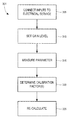
- FIG. 6B depicts a flow chart describing an alternative method 221 for calibrating a measured parameter in the IED.
- the meter 100 is connected, via the interface 107 or 109 to a reference current source and/or a reference voltage source, respectively, such as to the calibration reference 102 , depicted in FIG. 2 .
- the calibration reference 102 is adjusted until the signal amplitude provided by the calibration reference 102 causes the meter 100 to measure a desired value in the calibration range. For example, to calibrate the voltage measurements of the meter 100 in the 277 V calibration range, the calibration reference 102 may be adjusted until the value measured by the meter 100 is 20.000 V.
- the determined calibration factor is stored in the memory module 180 .
- the calibration factor may be determined using known methods. For example, a linear calibration factor (wherein multiplication of a measured value of a parameter by the calibration factor converts the measured value of the parameter to the actual value of the parameter), may be determined by dividing the reference value (i.e., the actual value of the parameter) by the value of the parameter as measured. This computation may be expressed as:
- F X R X M
- F the calibration factor
- X R the reference value of the parameter
- X M the value of the parameter as measured by the meter 100 .
- the steps 202 to 212 may be repeated for each of the values in a particular calibration range.
- the calibration range is 277 V
- calibration measurements may be made (and calibration factors determined) in, for example, 20 V increments (e.g., at 20 V, 40 V, 60 V, etc.).
- a plurality of calibration factors may be determined for the 277 V range of measurements. It should be noted that the number of measurements in a given calibration range may be as few as one.
- calibration measurements may be made at the range value (e.g., 277 V) and the full-scale value for that range (e.g., 500 V), instead of at smaller increments within the range.
- the meter 100 may determine one or more calibration factors using averaging or other statistical techniques.
- the method 201 (or the method 221 ) may be repeated, for each of the calibration ranges, at multiple frequencies (e.g., 50 Hz and 60 Hz), to allow the meter 100 to operate with improved accuracy regardless of the nominal operating frequency of the electrical system 101 .
- the meter 100 may store the determined calibration factor or factors as an individual value (e.g., where there is a single offset calibration factor or linear calibration factor for each calibration range) or in a look-up table or other data structure (e.g., where multiple offset or linear calibration factors exist for each calibration range).
- FIGS. 7A and 7B depict an example set of calibration measurements and a set of example linear calibration factors determined from the measurements that might result from the methods 201 and 221 , respectively.
- the tables 240 and 260 have five columns.
- a column 242 depicts example values of signals generated by the calibration reference 102 .
- a column 244 depicts example values of the signals generated by the calibration reference 102 , as measured by the meter 100 .
- a column 246 depicts the calibration factor calculated using the values in the columns 242 and 244 .
- columns 248 and 250 depict the error for the particular example reference value before and after application of the calibration factor, respectively.
- the first row in the column 242 of the table 240 shows a reference value of 20.00 V
- the column 244 of the table 240 indicates that the value measured by the meter 100 was 18.76 V.
- there is a measurement error of 6.200% (indicated in the column 248 of the table 240 ).
- the error is less than 0.2% (as depicted in the column 250 of the table 240 ).
- the method 201 shown in FIG. 6A (or the method 221 shown in FIG. 6B ) is repeated for each of the desired calibration ranges (e.g., 69 V, 120 V, 277 V, etc.).
- the memory module 180 of the meter 100 will contain calibration data 190 for each of the desired calibration ranges, allowing the meter 100 to operate with the desired accuracy (e.g., less than 0.2% error) in any of its intended operating ranges.
- the calibrated parameters need not be restricted to voltage and current. Additional parameters and/or measurements may also be calibrated in each of any number of desired calibration ranges. These parameters and/or measurements may include, by way of example and not limitation, RMS current, RMS voltage, phase, apparent power, reactive power, active power, frequency, etc.
- FIG. 8 depicts a method 301 , that may be implemented by the routine 300 , for using the stored calibration factors determined by the routine 200 and stored in the memory module 180 to determine a calibrated measurement (i.e., an actual value) of the measured parameter.
- the meter 100 is connected, via the interface 107 or 109 to an electrical service 101 which operates at a nominal voltage with a nominal frequency. Further, the load (not shown) on the electrical service 101 draws current at some nominal capacity.
- the processing module 120 assesses the appropriate gain for each of the measured current and voltage signals by first assessing the nominal values of the voltage and current in the electrical system 101 (i.e., ignoring the effects of transients, harmonics, etc.). The processing module 120 then determines the industry standard nominal value for the voltage (e.g., 69 V, 120 V, 230 V, 277 V, 347 V, 416 V, 721 V, etc.) and the industry standard nominal range for the current (e.g., 0-1 A, 0-5 A, or 0-10 A). Next, the processing module 120 selects the appropriate voltage gain and the appropriate current gain to optimally utilize the full resolution of the ADCs 112 A, 112 B, 112 C, 114 A, 114 B, 114 C.
- the industry standard nominal value for the voltage e.g., 69 V, 120 V, 230 V, 277 V, 347 V, 416 V, 721 V, etc.
- the industry standard nominal range for the current e.g.,
- gain adjustments for the supply voltages and currents may be performed in a real time (i.e., dynamically) by a gain control routine 164 or, alternatively, the gain factors for the amplifiers 111 A, 111 B, 111 C, 113 A, 113 B, 113 C may be pre-configured via the user interface 130 based on known characteristics of the electrical service 101 or electrical load, which power consumption is monitored using the meter 100 . Additionally, the gain control routine 164 may operate within the processor 160 of the metering module 120 , as described above and as depicted in FIG. 4 , or may operate within the metering processor 118 .
- the nominal values of the voltage and the current in the electrical system 101 may be determined from the output of the sensing module 115 (i.e., the voltage sensing circuitry 117 and current sensing circuitry 119 ) or, alternatively, from the output of the metering processor 118 .
- the step 310 allows the meter 100 to perform measurements of the voltages and currents, regardless of their nominal values, with the same high accuracy in the respective operating ranges of the meter 100 .
- the meter 100 measures the parameter to which calibration data is to be applied. For example, if calibration data exists for RMS voltage measurements (e.g., as the stored calibration data 190 within memory module 180 ), the meter 100 measures the RMS voltage of the electrical service 101 .
- the processing module 120 determines one or more appropriate calibration factors in a step 320 .
- the appropriate calibration factors may be selected based on one or more criteria including, for example, the amplitude of measured parameter, the gain factors applied to the current and/or voltage inputs, and the calibration range in which the meter 100 is operating (e.g., if the meter is attached to a 277 V system, the calibration factors for the 277 V calibration range may be selected).
- the meter 100 uses the one or more calibration factors determined in the step 320 to calculate a calibrated measurement (i.e., an actual value) of the measured value of the parameter.
- calculating the measured value of the parameter to find the actual value of the parameter may require adding the offset calibration factor (where offset calibration factors are employed instead of linear calibration factors) to the measured value of the parameter.
- X A X M +F
- X A X M +F
- FIGS. 9A and 9B depict methods 401 and 451 for determining one or more additional calibration factors using interpolation of the previously determined and stored calibration factors.
- the calibration method 201 described above, results in the calibration factors stored in the memory module 180 . While application of these calibration factors in accordance with, for example, routine 300 , produces accurate measurements at the calibration values for which measurements were taken, any measured value that falls between two adjacent values for which calibration factors exist may not be as accurate. For example, if calibration measurements were made (and corresponding calibration factors determined and stored) at 20 V and 40 V, a measured value between 20 V and 40 V would have no corresponding calibration factors. While in some circumstances one may be able to provide the required accuracy (e.g., less than 0.2% error) by applying calibration factors for one or the other of the two adjacent calibration measurements, increased accuracy may be provided by using interpolation to find a more accurate calibration factor.
- the required accuracy e.g., less than 0.2% error
- the method 401 of FIG. 9A determines one or more additional calibration data points using interpolation of the stored calibration data.
- the processing module 120 determines the calibration range in which the meter 100 is operating.
- Calibration factors (F 1 and F 2 ) for the two measured values (X M1 and X M2 ) of the parameter at which adjacent calibration measurements were taken are determined in a step 410 .
- the measured value (X M3 ) of the parameter is 30 V
- the two measured values (X M1 and X M2 ) adjacent points at which calibration measurements were taken may be 20 V and 40 V
- the corresponding linear calibration factors (F 1 and F 2 ) may be 1.100 and 1.300, respectively.
- the processing module 120 determines the slope b of a line drawn between the linear calibration factors.
- the slope b of such a line between the linear calibration factors may be determined by the equation:
- b ( F 2 - F 1 ) ( X M ⁇ ⁇ 2 - X M ⁇ ⁇ 1 )
- F 1 and F 2 are 1.100 and 1.300, respectively
- the processing module 120 applies the slope to find the new calibration factor F 3 in a step 420 .
- a step 425 may store the newly determined calibration factor for future use with the other calibration data 190 in the memory module 180 .
- the step 425 may store other or additional data, such as the slope b of the line between the calibration factors.
- Interpolation may also be applied to the values of the measured signals used to calibrate the meter 100 , as shown in the method 451 of FIG. 9B .
- the processing module 120 determines the calibration range in which the meter 100 is operating.
- a step 460 determines the actual values (X A1 and X A2 ) for the two measured values (X M1 and X M2 ) of the parameter at which adjacent calibration measurements were taken.
- the processing module 120 may find the corresponding actual values (X A1 and X A2 ) by calculating these actual values using the calibration factors (F 1 and F 2 ) stored in the memory module 180 as associated with the measured values (X M1 and X M2 ). This calculation may be expressed as:
- X A ⁇ ⁇ 1 ( X M ⁇ ⁇ 1 ) ( F 1 )
- X A ⁇ ⁇ 2 ( X M ⁇ ⁇ 2 ) ( F 2 )
- the actual values corresponding to the measured values could be stored in addition to, or instead of, the calibration factors, and the actual values may be retrieved directly from the memory module 180 instead of being calculated.
- both of methods 401 and 451 may also be used to determine, by interpolation, additional offset calibration factors.
- the processing module 120 determines the slope b of the actual values.
- the slope b of the actual values may be determined by the equation:
- b ( X A ⁇ ⁇ 2 - X A ⁇ ⁇ 1 ) ( X M ⁇ ⁇ 2 - X M ⁇ ⁇ 1 )
- X A1 and X A2 are 19.802 V and 38.835 V, respectively
- the processing module 120 uses the slope b to find the new actual value X A3 in a step 470 .
- a step 475 may store this value in the memory module 180 for future use.
- the above procedures may also be used to determine, by interpolation, calibration factors (or calibrated measurement values) at frequencies other than the frequencies at which the meter 100 may be calibrated (e.g., 50 Hz and 60 Hz).
- the extrapolation process starts with determining the two (but not limited to) calibration factors closest to the range of the measured parameter.
- the next step is to apply the extrapolation algorithm to determine the approximated calibration factor at the given point where the parameter is measured at.
- the extrapolation algorithm calculates the magnitude difference of the two factors (factor 1 , factor 2 ), and then calculates the ratio of the variable range between the measurement point and factor 1 , and the range between factor 1 and factor 2 .
- each independently-adjustable gain channel allows the meter to use the associated analog-to-digital converter in the most appropriate resolution for the channel's dedicated task, while the plurality of ranges over which the meter 100 is calibrated allows improved accuracy across multiple input ranges.
- the combination of features allows the meter 100 to accurately measure some electrical parameters (e.g., current, voltage, etc.) over a wide range of input values, while still providing sufficiently detailed capture and/or analysis of other electrical parameters (e.g., waveform, harmonics, etc.).
- IEDs Intelligent Electronic Devices
- PLCs Programmable Logic Controllers
- RTUs Remote Terminal Units
- protective relays fault recorders
- other devices or systems used to quantify, manage, and control quality, distribution, and consumption of electrical power.
- digital electrical power and energy meter refers broadly to any IED adapted to record, measure, communicate, or act in response to one or more parameters of an electrical service.
- These parameters may include, for example, supply currents and supply voltages, their waveforms, harmonics, transients, and other disturbances, and other corresponding parameters, such as power, power quality, energy, revenue, and the like.
- a variety of electrical service environments may employ IEDs and, in particular, digital electrical power and energy meters.
- these environments include power generation facilities (e.g., hydroelectric plants, nuclear power plants, etc.), power distribution networks and facilities, industrial process environments (e.g., factories, refineries, etc.), and backup generation facilities (e.g., backup generators for a hospital, a factory, etc.).
Abstract
Description
where F is the calibration factor, XR is the reference value of the parameter, and XM is the value of the parameter as measured by the
F=X R −X M
X A =X M *F
where XA is the actual value of the parameter, XM is the measured value of the parameter, and F is the chosen calibration factor. Alternatively, calculating the measured value of the parameter to find the actual value of the parameter may require adding the offset calibration factor (where offset calibration factors are employed instead of linear calibration factors) to the measured value of the parameter. This operation may be expressed mathematically as:
X A =X M +F
The re-calculated data (i.e., XA) for the parameter is then selectively stored in the
In the example above, F1 and F2 are 1.100 and 1.300, respectively, and XM1 and XM2 are 20 V and 40 V, respectively. Therefore, b=0.10.
F 3=(X M3 −X M2)b+F 2
Applying this equation in the example above to find a calibration factor to apply to a measured value of 30 V (i.e., XM3=30 V), it is determined that the calibration factor F3 is 1.200. This new calibration factor may be applied to the measured value to find the actual value (XA3) in the same manner as described with reference to the method 301 (i.e., XA3=F3*XM3). Optionally, a
Alternatively, the actual values corresponding to the measured values could be stored in addition to, or instead of, the calibration factors, and the actual values may be retrieved directly from the
In the example above, XA1 and XA2 are 19.802 V and 38.835 V, respectively, and XM1 and XM2 are 20 V and 40 V, respectively. Therefore, in this example, b=0.001.
X A3=(X M3 −X M2)b+X A2
Applying this equation in the example above to find the actual value XA3 of a measured value of 30 V (i.e., XM3=30 V), it is determined that the actual value XA3 is 29.319 V. Of course, if desired, a
Claims (22)
Priority Applications (3)
| Application Number | Priority Date | Filing Date | Title |
|---|---|---|---|
| US12/055,448 US7996171B2 (en) | 2005-01-27 | 2008-03-26 | Intelligent electronic device with broad-range high accuracy |
| US13/204,789 US8878517B2 (en) | 2005-01-27 | 2011-08-08 | Intelligent electronic device with broad-range high accuracy |
| US14/530,767 US10345416B2 (en) | 2007-03-27 | 2014-11-02 | Intelligent electronic device with broad-range high accuracy |
Applications Claiming Priority (5)
| Application Number | Priority Date | Filing Date | Title |
|---|---|---|---|
| US64766905P | 2005-01-27 | 2005-01-27 | |
| US11/341,802 US7337081B1 (en) | 2005-01-27 | 2006-01-27 | Metering device with control functionality and method thereof |
| US92012807P | 2007-03-27 | 2007-03-27 | |
| US12/036,356 US7899630B2 (en) | 2005-01-27 | 2008-02-25 | Metering device with control functionality and method thereof |
| US12/055,448 US7996171B2 (en) | 2005-01-27 | 2008-03-26 | Intelligent electronic device with broad-range high accuracy |
Related Parent Applications (1)
| Application Number | Title | Priority Date | Filing Date |
|---|---|---|---|
| US12/036,356 Continuation-In-Part US7899630B2 (en) | 2004-10-20 | 2008-02-25 | Metering device with control functionality and method thereof |
Related Child Applications (1)
| Application Number | Title | Priority Date | Filing Date |
|---|---|---|---|
| US13/204,789 Continuation US8878517B2 (en) | 2005-01-27 | 2011-08-08 | Intelligent electronic device with broad-range high accuracy |
Publications (2)
| Publication Number | Publication Date |
|---|---|
| US20080172192A1 US20080172192A1 (en) | 2008-07-17 |
| US7996171B2 true US7996171B2 (en) | 2011-08-09 |
Family
ID=46330225
Family Applications (2)
| Application Number | Title | Priority Date | Filing Date |
|---|---|---|---|
| US12/055,448 Active 2029-03-13 US7996171B2 (en) | 2005-01-27 | 2008-03-26 | Intelligent electronic device with broad-range high accuracy |
| US13/204,789 Active 2029-01-09 US8878517B2 (en) | 2005-01-27 | 2011-08-08 | Intelligent electronic device with broad-range high accuracy |
Family Applications After (1)
| Application Number | Title | Priority Date | Filing Date |
|---|---|---|---|
| US13/204,789 Active 2029-01-09 US8878517B2 (en) | 2005-01-27 | 2011-08-08 | Intelligent electronic device with broad-range high accuracy |
Country Status (1)
| Country | Link |
|---|---|
| US (2) | US7996171B2 (en) |
Cited By (24)
| Publication number | Priority date | Publication date | Assignee | Title |
|---|---|---|---|---|
| US20080238406A1 (en) * | 2007-03-27 | 2008-10-02 | Electro Industries/Gauge Tech. | Intelligent Electronic Device Having Improved Analog Output Resolution |
| US20090012728A1 (en) * | 2005-01-27 | 2009-01-08 | Electro Industries/Gauge Tech. | System and Method for Multi-Rate Concurrent Waveform Capture and Storage for Power Quality Metering |
| US20090080490A1 (en) * | 2007-09-21 | 2009-03-26 | Siemens Energy & Automation, Inc. | Systems, Devices, and/or Methods for Managing a Thermocouple Module |
| US20130043725A1 (en) * | 2009-07-31 | 2013-02-21 | Mogen Birkelund | Method and Apparatus for Managing Transmission of Power in a Power Transmission Network |
| US8737033B2 (en) | 2012-09-10 | 2014-05-27 | Eaton Corporation | Circuit interrupter employing non-volatile memory for improved diagnostics |
| US8878517B2 (en) | 2005-01-27 | 2014-11-04 | Electro Industries/Gauge Tech | Intelligent electronic device with broad-range high accuracy |
| US8930153B2 (en) | 2005-01-27 | 2015-01-06 | Electro Industries/Gauge Tech | Metering device with control functionality and method thereof |
| US20150120230A1 (en) * | 2007-03-27 | 2015-04-30 | Electro Industries/Gauge Tech | Intelligent electronic device with broad-range high accuracy |
| US9194898B2 (en) | 2005-01-27 | 2015-11-24 | Electro Industries/Gauge Tech | Intelligent electronic device and method thereof |
| US9594098B2 (en) | 2009-09-25 | 2017-03-14 | Belkin International Inc. | Systems and methods for measuring electrical power usage in a structure and systems and methods of calibrating the same |
| US9766277B2 (en) | 2009-09-25 | 2017-09-19 | Belkin International, Inc. | Self-calibrating contactless power consumption sensing |
| US9857449B2 (en) | 2010-07-02 | 2018-01-02 | Belkin International, Inc. | System and method for monitoring electrical power usage in an electrical power infrastructure of a building |
| US9989618B2 (en) | 2007-04-03 | 2018-06-05 | Electro Industries/Gaugetech | Intelligent electronic device with constant calibration capabilities for high accuracy measurements |
| US10247765B2 (en) | 2007-09-18 | 2019-04-02 | Georgia Tech Research Corporation | Detecting actuation of electrical devices using electrical noise over a power line |
| US10288646B2 (en) | 2015-02-26 | 2019-05-14 | Potential Labs, Llc | Determining energy usage of a residence based on current monitoring |
| CN110346663A (en) * | 2019-07-04 | 2019-10-18 | 广东科瑞德电气科技有限公司 | A kind of method of electric locomotive by pyroelectric monitor terminal fault recording |
| US10628053B2 (en) | 2004-10-20 | 2020-04-21 | Electro Industries/Gauge Tech | Intelligent electronic device for receiving and sending data at high speeds over a network |
| US10641618B2 (en) | 2004-10-20 | 2020-05-05 | Electro Industries/Gauge Tech | On-line web accessed energy meter |
| US10845399B2 (en) | 2007-04-03 | 2020-11-24 | Electro Industries/Gaugetech | System and method for performing data transfers in an intelligent electronic device |
| US11307227B2 (en) | 2007-04-03 | 2022-04-19 | Electro Industries/Gauge Tech | High speed digital transient waveform detection system and method for use in an intelligent electronic device |
| US11366143B2 (en) | 2005-01-27 | 2022-06-21 | Electro Industries/Gaugetech | Intelligent electronic device with enhanced power quality monitoring and communication capabilities |
| US11366145B2 (en) | 2005-01-27 | 2022-06-21 | Electro Industries/Gauge Tech | Intelligent electronic device with enhanced power quality monitoring and communications capability |
| US11644490B2 (en) | 2007-04-03 | 2023-05-09 | El Electronics Llc | Digital power metering system with serial peripheral interface (SPI) multimaster communications |
| US11686749B2 (en) | 2004-10-25 | 2023-06-27 | El Electronics Llc | Power meter having multiple ethernet ports |
Families Citing this family (53)
| Publication number | Priority date | Publication date | Assignee | Title |
|---|---|---|---|---|
| US8078418B2 (en) * | 2005-01-27 | 2011-12-13 | Electro Industries/Gauge Tech | Intelligent electronic device and method thereof |
| US8666688B2 (en) | 2005-01-27 | 2014-03-04 | Electro Industries/Gauge Tech | High speed digital transient waveform detection system and method for use in an intelligent electronic device |
| US8797202B2 (en) | 2008-03-13 | 2014-08-05 | Electro Industries/Gauge Tech | Intelligent electronic device having circuitry for highly accurate voltage sensing |
| US9482555B2 (en) | 2008-04-03 | 2016-11-01 | Electro Industries/Gauge Tech. | System and method for improved data transfer from an IED |
| US7822578B2 (en) * | 2008-06-17 | 2010-10-26 | General Electric Company | Systems and methods for predicting maintenance of intelligent electronic devices |
| ATE530962T1 (en) * | 2008-06-25 | 2011-11-15 | Abb Research Ltd | FLEXIBLE SMART ELECTRONIC DEVICE |
| US8560255B2 (en) * | 2008-12-12 | 2013-10-15 | Schneider Electric USA, Inc. | Power metering and merging unit capabilities in a single IED |
| US9134348B2 (en) | 2009-04-16 | 2015-09-15 | Panoramic Power Ltd. | Distributed electricity metering system |
| US9678114B2 (en) * | 2009-04-16 | 2017-06-13 | Panoramic Power Ltd. | Apparatus and methods thereof for error correction in split core current transformers |
| GB2481778B (en) | 2009-04-16 | 2014-02-05 | Panoramic Power Ltd | Apparatus and methods thereof for power consumption measurement at circuit breaker points |
| US8203814B2 (en) * | 2009-08-31 | 2012-06-19 | Eaton Corporation | Electrical switching apparatus including a plurality of Rogowski coils and method of calibrating the same |
| US8930152B2 (en) * | 2009-09-25 | 2015-01-06 | University Of Washington | Whole structure contactless power consumption sensing |
| CN101860080B (en) * | 2010-05-18 | 2012-07-04 | 武汉国测科技股份有限公司 | Distribution network metering and protection integral device suspended at high-voltage side |
| US8942942B2 (en) * | 2010-07-23 | 2015-01-27 | Caterpillar Inc. | Generator set calibration controller |
| CN202008526U (en) * | 2011-03-07 | 2011-10-12 | 安徽省电力科学研究院 | Accuracy verification system for digital signal based electric energy quality measurement device |
| CN102227090B (en) * | 2011-06-27 | 2013-08-21 | 山西省电力公司临汾供电分公司 | Intelligent FA (feeder automation) system of 10kV-carrier communication |
| KR101486992B1 (en) * | 2011-08-16 | 2015-02-06 | 한국전력공사 | Apparatus and method for detecting line connecting default of smart meter |
| CN102508015B (en) * | 2011-09-29 | 2013-12-04 | 南京国电南自轨道交通工程有限公司 | Three-in-one real-time load curve construction method for railway power supply system |
| US10303860B2 (en) | 2011-10-04 | 2019-05-28 | Electro Industries/Gauge Tech | Security through layers in an intelligent electronic device |
| US10862784B2 (en) | 2011-10-04 | 2020-12-08 | Electro Industries/Gauge Tech | Systems and methods for processing meter information in a network of intelligent electronic devices |
| US10771532B2 (en) | 2011-10-04 | 2020-09-08 | Electro Industries/Gauge Tech | Intelligent electronic devices, systems and methods for communicating messages over a network |
| US10275840B2 (en) | 2011-10-04 | 2019-04-30 | Electro Industries/Gauge Tech | Systems and methods for collecting, analyzing, billing, and reporting data from intelligent electronic devices |
| CN102520226B (en) * | 2011-12-06 | 2014-08-13 | 广东电网公司电力科学研究院 | Low current compensation method for electric energy measurement |
| US9252588B2 (en) * | 2011-12-20 | 2016-02-02 | Landis+Gyr, Inc. | Service voltage load protection in an electric utility meter |
| CA2861414A1 (en) * | 2012-01-19 | 2013-07-25 | Awesense Wireless Inc. | System and method for linear measurement of ac waveforms with low voltage non-linear sensors in high voltage environments |
| CN103296638A (en) * | 2012-02-29 | 2013-09-11 | 鸿富锦精密工业(深圳)有限公司 | Electronic equipment and power down protection device and method applied to electronic equipment |
| RU2518846C2 (en) * | 2012-08-06 | 2014-06-10 | Федеральное Государственное Автономное Образовательное Учреждение Высшего Профессионального Образования "Дальневосточный Федеральный Университет" (Двфу) | Active current measuring device |
| JP2015537116A (en) * | 2012-10-05 | 2015-12-24 | ミオックス コーポレーション | On-site generation without transformer |
| WO2014094782A1 (en) * | 2012-12-18 | 2014-06-26 | Miitors Aps | Utility meter controlling the conversion range of an adc |
| US11816465B2 (en) | 2013-03-15 | 2023-11-14 | Ei Electronics Llc | Devices, systems and methods for tracking and upgrading firmware in intelligent electronic devices |
| US10145903B2 (en) * | 2013-08-09 | 2018-12-04 | Abb Schweiz Ag | Methods and systems for monitoring devices in a power distribution system |
| KR101488104B1 (en) * | 2013-10-02 | 2015-01-29 | 한국수력원자력 주식회사 | System for Detecting Open Phase on a Connection Line of Stand-by Transformer in Nuclear Power Plant by Using Rogowski Coil |
| US11734396B2 (en) | 2014-06-17 | 2023-08-22 | El Electronics Llc | Security through layers in an intelligent electronic device |
| JP6738325B2 (en) * | 2014-09-12 | 2020-08-12 | ベルキン・インターナショナル・インコーポレイテッド | Self-calibrating contactless power consumption sensing |
| CN104503897B (en) * | 2014-10-21 | 2017-07-21 | 惠州市龙鼎盛电力科技有限公司 | A kind of electric energy meter software design method that a variety of interactive modes can be achieved |
| RU2580410C1 (en) * | 2014-12-31 | 2016-04-10 | Федеральное государственное автономное образовательное учреждение высшего образования "Национальный исследовательский Томский политехнический университет" | Device for measuring high currents |
| FR3039281B1 (en) * | 2015-07-21 | 2017-08-18 | Sagemcom Energy & Telecom Sas | METHOD FOR MEASURING ENERGY CONSUMPTION OF AN ELECTRICAL INSTALLATION |
| US10024885B2 (en) | 2015-07-28 | 2018-07-17 | Panoramic Power Ltd. | Thermal management of self-powered power sensors |
| US9891252B2 (en) | 2015-07-28 | 2018-02-13 | Panoramic Power Ltd. | Thermal management of self-powered power sensors |
| US10958435B2 (en) | 2015-12-21 | 2021-03-23 | Electro Industries/ Gauge Tech | Providing security in an intelligent electronic device |
| US10430263B2 (en) | 2016-02-01 | 2019-10-01 | Electro Industries/Gauge Tech | Devices, systems and methods for validating and upgrading firmware in intelligent electronic devices |
| US20170248639A1 (en) * | 2016-02-26 | 2017-08-31 | Siemens Industry, Inc. | Self-phasing electric meter and automation system |
| FR3050034B1 (en) * | 2016-04-12 | 2019-08-02 | Sagemcom Energy & Telecom Sas | METHOD FOR DETECTING A FAULT IN AN ELECTRIC ENERGY METER COMPRISING A CUTTING MEMBER |
| CN106226721B (en) * | 2016-09-22 | 2018-11-09 | 许昌许继软件技术有限公司 | A kind of fault oscillograph starting performance test method and system |
| US11734704B2 (en) | 2018-02-17 | 2023-08-22 | Ei Electronics Llc | Devices, systems and methods for the collection of meter data in a common, globally accessible, group of servers, to provide simpler configuration, collection, viewing, and analysis of the meter data |
| US11754997B2 (en) | 2018-02-17 | 2023-09-12 | Ei Electronics Llc | Devices, systems and methods for predicting future consumption values of load(s) in power distribution systems |
| US11686594B2 (en) | 2018-02-17 | 2023-06-27 | Ei Electronics Llc | Devices, systems and methods for a cloud-based meter management system |
| CN108802663B (en) * | 2018-04-18 | 2020-12-01 | 电子科技大学 | Intelligent electric energy meter function verification method based on source regulation parameter vector optimization |
| CN109901090B (en) * | 2019-03-26 | 2020-08-04 | 国网北京市电力公司 | Measurement and control equipment of transformer substation |
| US11863589B2 (en) | 2019-06-07 | 2024-01-02 | Ei Electronics Llc | Enterprise security in meters |
| US11408920B2 (en) * | 2019-11-01 | 2022-08-09 | Landis+Gyr Innovations, Inc. | Crosstalk cancelation for electricity metering |
| CN111505562B (en) * | 2020-04-29 | 2023-03-17 | 内蒙古电力(集团)有限责任公司 | Test system for metering performance self-monitoring capability of electric energy meter |
| CN112363001A (en) * | 2020-11-24 | 2021-02-12 | 科大智能电气技术有限公司 | High-precision metering method and system for platform area intelligent fusion terminal |
Citations (21)
| Publication number | Priority date | Publication date | Assignee | Title |
|---|---|---|---|---|
| US3333194A (en) * | 1965-08-11 | 1967-07-25 | Batcher Ralph Reynolds | Meter to measure and print-out the ratio of a measured parameter to a calibrated standard value |
| US3535637A (en) * | 1967-10-26 | 1970-10-20 | Saab Ab | Calibration of electrical measuring transducer devices |
| US3824441A (en) | 1973-01-02 | 1974-07-16 | Honeywell Inf Systems | Multivoltage, regulated power supply with fault protection |
| US4689752A (en) * | 1983-04-13 | 1987-08-25 | Niagara Mohawk Power Corporation | System and apparatus for monitoring and control of a bulk electric power delivery system |
| US4884021A (en) * | 1987-04-24 | 1989-11-28 | Transdata, Inc. | Digital power metering |
| US4996646A (en) | 1988-03-31 | 1991-02-26 | Square D Company | Microprocessor-controlled circuit breaker and system |
| US5166887A (en) | 1988-03-31 | 1992-11-24 | Square D Company | Microcomputer-controlled circuit breaker system |
| US5170360A (en) | 1988-03-31 | 1992-12-08 | Square D Company | Computer-based metering arrangement including a circuit interrupter |
| JPH08247783A (en) * | 1995-03-13 | 1996-09-27 | Omron Corp | Transducer |
| US6018690A (en) | 1996-09-13 | 2000-01-25 | Kabushiki Kaisha Toshiba | Power supply control method, power supply control system and computer program product |
| US6032109A (en) * | 1996-10-21 | 2000-02-29 | Telemonitor, Inc. | Smart sensor module |
| US6098175A (en) | 1998-02-24 | 2000-08-01 | Smartpower Corporation | Energy-conserving power-supply system |
| US6167329A (en) | 1998-04-06 | 2000-12-26 | Eaton Corporation | Dual microprocessor electronic trip unit for a circuit interrupter |
| US6528957B1 (en) | 1999-09-08 | 2003-03-04 | Lutron Electronics, Co., Inc. | Power/energy management control system |
| US20030187550A1 (en) | 2002-04-01 | 2003-10-02 | Wilson Thomas L. | Electrical power distribution control systems and processes |
| US6735535B1 (en) * | 2000-05-05 | 2004-05-11 | Electro Industries/Gauge Tech. | Power meter having an auto-calibration feature and data acquisition capabilities |
| US20050165585A1 (en) * | 2004-01-26 | 2005-07-28 | Anr, L.P. | Flexible process optimizer |
| US7337081B1 (en) * | 2005-01-27 | 2008-02-26 | Electro Industries/Gauge Tech | Metering device with control functionality and method thereof |
| US20080147334A1 (en) * | 2005-01-27 | 2008-06-19 | Electro Industries/Gauge Tech. | Metering Device with Control Functionally and Method Thereof |
| US20080234957A1 (en) * | 2005-01-27 | 2008-09-25 | Electro Industries/Gauge Tech. | Intelligent Electronic Device and Method Thereof |
| US20090228224A1 (en) * | 2005-01-27 | 2009-09-10 | Electro Industries/Gauge Tech. | Intelligent electronic device with enhanced power quality monitoring and communications capabilities |
Family Cites Families (95)
| Publication number | Priority date | Publication date | Assignee | Title |
|---|---|---|---|---|
| US2992365A (en) | 1955-03-24 | 1961-07-11 | Everett C Brill | Watt-sensing device |
| CA606427A (en) | 1955-05-20 | 1960-10-04 | B. Squires Rathbun | Electrical measuring system |
| DE1161993B (en) | 1959-09-23 | 1964-01-30 | Gossen & Co Gmbh P | Multimeter for alternating current |
| US3084863A (en) | 1962-02-19 | 1963-04-09 | W W Henry Company | Analogue computer |
| US3458810A (en) | 1964-12-29 | 1969-07-29 | Herman Wald | Remote group metering of electric energy for multistory buildings with current transformer |
| US4066960A (en) | 1976-12-29 | 1978-01-03 | General Electric Company | Electronic kilowatt-hour-meter with error correction |
| US4077061A (en) | 1977-03-25 | 1978-02-28 | Westinghouse Electric Corporation | Digital processing and calculating AC electric energy metering system |
| US4182983A (en) | 1978-07-11 | 1980-01-08 | Westinghouse Electric Corp. | Electronic AC electric energy measuring circuit |
| GB2040051B (en) | 1979-01-11 | 1982-12-08 | South Eastern Elec Board | Electroni kolowatthour meter |
| US4240149A (en) | 1979-02-16 | 1980-12-16 | Leeds & Northrup Company | Measuring system |
| US4283772A (en) | 1979-03-30 | 1981-08-11 | Westinghouse Electric Corp. | Programmable time registering AC electric energy meter having electronic accumulators and display |
| SE425123B (en) | 1979-08-21 | 1982-08-30 | Bjorn Gosta Erik Karlsson | PLANT FOR CENTRAL AND AUTOMATIC READING AND REGISTRATION OF SUBSCRIBERS 'ENERGY CONSUMPTION |
| US4463311A (en) | 1980-05-29 | 1984-07-31 | Tokyo Shibaura Denki Kabushiki Kaisha | Electronic electric-energy meter |
| US4360879A (en) | 1980-08-28 | 1982-11-23 | The Valeron Corporation | Power measuring device |
| US4437059A (en) | 1980-10-21 | 1984-03-13 | Rochester Instrument Systems, Inc. | Wattmeter |
| US4933633A (en) | 1981-06-09 | 1990-06-12 | Adec, Inc. | Computer controlled energy monitoring system |
| US4486707A (en) | 1982-09-24 | 1984-12-04 | Sangamo Weston, Inc. | Gain switching device with reduced error for watt meter |
| US4608533A (en) | 1983-06-22 | 1986-08-26 | Electric Power Research Institute, Inc. | Automatic compensation circuit for use with analog multiplier |
| US4713609A (en) | 1985-09-05 | 1987-12-15 | General Electric Company | Battery backup installation for electric meter |
| CH673160A5 (en) | 1986-02-10 | 1990-02-15 | Landis & Gyr Ag | |
| US4713608A (en) | 1986-03-06 | 1987-12-15 | Computer Power Systems Corporation | Apparatus for providing cost efficient power measurement |
| JPH0697256B2 (en) | 1986-04-14 | 1994-11-30 | 株式会社アドバンテスト | AC level calibration device |
| YU46409B (en) | 1986-07-15 | 1993-10-20 | Iskra Kibernetika | ELECTRIC POWER METER WITH HALL SENSOR AND A / D CONVERTER |
| US4839819A (en) | 1986-08-14 | 1989-06-13 | Cte Valeron Corporation | Intelligent power monitor |
| US4989155A (en) | 1986-08-14 | 1991-01-29 | Gte Valenite Corporation | Intelligent power monitor |
| US4902965A (en) | 1987-06-15 | 1990-02-20 | Bodrug John D | Consumption meter for accumulating digital power consumption signals via telephone lines without disturbing the consumer |
| US5079715A (en) | 1987-12-28 | 1992-01-07 | Krishnan Venkataraman | Electronic data recorder for electric energy metering |
| US4958294A (en) | 1988-04-01 | 1990-09-18 | Wavetek Microwave, Inc. | Swept microwave power measurement system and method |
| US4949029A (en) | 1988-07-15 | 1990-08-14 | Schulmberger Industries, Inc. | Adjustment circuit and method for solid-state electricity meter |
| US4999572A (en) | 1988-09-19 | 1991-03-12 | General Electric Company | Redundant pulse monitoring in electric energy metering system |
| US5017860A (en) | 1988-12-02 | 1991-05-21 | General Electric Company | Electronic meter digital phase compensation |
| US5014229A (en) | 1989-02-08 | 1991-05-07 | Basic Measuring Instruments | Method and apparatus for calibrating transducer/amplifier systems |
| US5258704A (en) | 1989-09-25 | 1993-11-02 | General Electric Company | Electronic watthour meter |
| CA2021078A1 (en) | 1989-09-25 | 1991-03-26 | Warren Ralph Germer | Electronic watthour meter |
| US5245275A (en) | 1989-09-25 | 1993-09-14 | General Electric Company | Electronic watthour meter |
| FR2656427B1 (en) | 1989-12-22 | 1992-03-13 | Cit Alcatel | CIRCUIT FOR MEASURING THE LEVEL OF AN ELECTRICAL SIGNAL COMPRISING MEANS FOR OFFSET CORRECTION AND APPLICATION TO AMPLIFIERS WITH AUTOMATIC GAIN CONTROL. |
| US5132610A (en) | 1990-02-07 | 1992-07-21 | Ying Chang Liu | Digitizing power meter |
| US5122735A (en) | 1990-06-14 | 1992-06-16 | Transdata, Inc. | Digital power metering |
| US5563506A (en) | 1990-07-10 | 1996-10-08 | Polymeters Response International Limited | Electricity meters using current transformers |
| EP0473877B1 (en) | 1990-08-23 | 1996-07-17 | Yokogawa Electric Corporation | Sampling type measuring device |
| US5243536A (en) | 1990-08-30 | 1993-09-07 | Metricom, Inc. | Method and apparatus for measuring volt-amps reactive power using synthesized voltage phase shift |
| US5229713A (en) | 1991-04-25 | 1993-07-20 | General Electric Company | Method for determining electrical energy consumption |
| US5248967A (en) | 1991-04-26 | 1993-09-28 | Marek Daneshfar | Method and apparatus for monitoring electrical devices |
| US5248935A (en) | 1991-05-20 | 1993-09-28 | Kabushiki Kaisha Toshiba | Electronic type watthour meter including automatic measuring-error correcting function |
| US5301121A (en) | 1991-07-11 | 1994-04-05 | General Electric Company | Measuring electrical parameters of power line operation, using a digital computer |
| US5391983A (en) | 1991-10-08 | 1995-02-21 | K C Corp. | Solid state electric power usage meter and method for determining power usage |
| JPH0772740B2 (en) | 1991-11-29 | 1995-08-02 | 株式会社椿本チエイン | Power detector |
| US5343143A (en) | 1992-02-11 | 1994-08-30 | Landis & Gyr Metering, Inc. | Shielded current sensing device for a watthour meter |
| MX9206230A (en) | 1992-02-21 | 1993-09-01 | Abb Power T & D Co | IMPROVEMENTS IN AN ELECTRICAL ACTIVITY METER AND METHODS FOR THE USE OF THE SAME. |
| US5298859A (en) | 1992-02-25 | 1994-03-29 | Basic Measuring Instruments | Harmonic-adjusted watt-hour meter |
| US5212441A (en) | 1992-02-25 | 1993-05-18 | Basic Measuring Instruments, Inc. | Harmonic-adjusted power factor meter |
| US5459459A (en) | 1992-12-28 | 1995-10-17 | General Electric Company | Method and apparatus for transmitting data from an energy meter |
| US5406495A (en) | 1993-02-01 | 1995-04-11 | Systems Analysis And Integration, Inc. | Substation load distribution monitor system |
| US20020186000A1 (en) | 1993-03-26 | 2002-12-12 | Briese Forrest Wayne | Electronic revenue meter with automatic service sensing |
| US5528507A (en) | 1993-08-11 | 1996-06-18 | First Pacific Networks | System for utility demand monitoring and control using a distribution network |
| US5453697A (en) | 1993-09-09 | 1995-09-26 | Carma Industries | Technique for calibrating a transformer element |
| US5737231A (en) | 1993-11-30 | 1998-04-07 | Square D Company | Metering unit with enhanced DMA transfer |
| US5514958A (en) * | 1994-11-22 | 1996-05-07 | General Electric Company | Electrical energy meters having factory set calibration circuits therein and methods of calibrating same |
| US6023160A (en) | 1994-12-19 | 2000-02-08 | General Electric Company | Electrical metering system having an electrical meter and an external current sensor |
| US6694270B2 (en) | 1994-12-30 | 2004-02-17 | Power Measurement Ltd. | Phasor transducer apparatus and system for protection, control, and management of electricity distribution systems |
| US5736847A (en) | 1994-12-30 | 1998-04-07 | Cd Power Measurement Limited | Power meter for determining parameters of muliphase power lines |
| US5650936A (en) | 1994-12-30 | 1997-07-22 | Cd Power Measurement Limited | Power monitor apparatus and method with object oriented structure |
| US5706214A (en) | 1995-03-29 | 1998-01-06 | Eaton Corporation | Calibration of microcomputer-based metering apparatus |
| US5627759A (en) | 1995-05-31 | 1997-05-06 | Process Systems, Inc. | Electrical energy meters having real-time power quality measurement and reporting capability |
| DE19534528A1 (en) | 1995-09-08 | 1997-03-13 | Francotyp Postalia Gmbh | Method for changing the data of an electronic franking machine loaded in memory cells |
| US5642300A (en) | 1996-01-26 | 1997-06-24 | Rotek Instrument Corp. | Precision voltage/current/power source |
| US5862391A (en) | 1996-04-03 | 1999-01-19 | General Electric Company | Power management control system |
| JP3195913B2 (en) | 1996-04-30 | 2001-08-06 | 株式会社東芝 | Semiconductor integrated circuit device |
| US5994892A (en) | 1996-07-31 | 1999-11-30 | Sacramento Municipal Utility District | Integrated circuit design automatic utility meter: apparatus & method |
| US5995911A (en) | 1997-02-12 | 1999-11-30 | Power Measurement Ltd. | Digital sensor apparatus and system for protection, control, and management of electricity distribution systems |
| US5897607A (en) | 1997-02-28 | 1999-04-27 | Jenney Systems Associates, Ltd. | Automatic meter reading system |
| US5963734A (en) | 1997-04-03 | 1999-10-05 | Abb Power T&D Company Inc. | Method and apparatus for configuring an intelligent electronic device for use in supervisory control and data acquisition system verification |
| GB9710912D0 (en) | 1997-05-27 | 1997-07-23 | Abb Metering Syst Ltd | Commodity consumption meters |
| US6262672B1 (en) | 1998-08-14 | 2001-07-17 | General Electric Company | Reduced cost automatic meter reading system and method using locally communicating utility meters |
| US6064192A (en) | 1998-04-08 | 2000-05-16 | Ohio Semitronics | Revenue meter with integral current transformer |
| US6757628B1 (en) | 1998-07-14 | 2004-06-29 | Landis+Gyr Inc. | Multi-level transformer and line loss compensator and method |
| US6401054B1 (en) | 1998-12-28 | 2002-06-04 | General Electric Company | Method of statistical analysis in an intelligent electronic device |
| US6374084B1 (en) | 1999-02-01 | 2002-04-16 | Avaya Technology Corp. | Method and system for calibrating electronic devices using polynomial fit calibration scheme |
| CA2387941C (en) | 1999-10-21 | 2007-04-24 | Siemens Power Transmission & Distribution, Inc. | External transformer correction in an electricity meter |
| AU2000225155A1 (en) | 2000-01-26 | 2001-08-07 | Abb Automation Inc. | System and method for digitally compensating frequency and temperature induced errors in amplitude and phase shift in current sensing of electronic energy meters |
| US6429637B1 (en) | 2000-08-04 | 2002-08-06 | Analog Devices, Inc. | Electronic power meter with phase and non-linearity compensation |
| US6590380B2 (en) | 2000-12-11 | 2003-07-08 | Thomas G. Edel | Method and apparatus for compensation of current transformer error |
| US6671635B1 (en) | 2001-02-23 | 2003-12-30 | Power Measurement Ltd. | Systems for improved monitoring accuracy of intelligent electronic devices |
| US6871150B2 (en) | 2001-02-23 | 2005-03-22 | Power Measurement Ltd. | Expandable intelligent electronic device |
| US6636028B2 (en) | 2001-06-01 | 2003-10-21 | General Electric Company | Electronic electricity meter configured to correct for transformer inaccuracies |
| US6714881B2 (en) | 2001-08-14 | 2004-03-30 | Square D Company | Time reference compensation for improved metering accuracy |
| US6759837B2 (en) | 2001-08-28 | 2004-07-06 | Analog Devices, Inc. | Methods and apparatus for phase compensation in electronic energy meters |
| US7174261B2 (en) | 2003-03-19 | 2007-02-06 | Power Measurement Ltd. | Power line sensors and systems incorporating same |
| US7337080B2 (en) | 2004-06-25 | 2008-02-26 | Power Measurement, Ltd. | Method and apparatus for instrument transformer reclassification |
| CA2484742A1 (en) | 2004-09-28 | 2006-03-28 | Veris Industries, Llc | Electricity metering with a current transformer |
| US7305310B2 (en) | 2004-10-18 | 2007-12-04 | Electro Industries/Gauge Tech. | System and method for compensating for potential and current transformers in energy meters |
| US7996171B2 (en) | 2005-01-27 | 2011-08-09 | Electro Industries/Gauge Tech | Intelligent electronic device with broad-range high accuracy |
| US7916060B2 (en) | 2005-01-27 | 2011-03-29 | Electro Industries/Gauge Tech. | Intelligent electronic device having circuitry for noise reduction for analog-to-digital converters |
| US7729445B2 (en) * | 2006-09-27 | 2010-06-01 | Intel Corporation | Digital outphasing transmitter architecture |
| US8797202B2 (en) | 2008-03-13 | 2014-08-05 | Electro Industries/Gauge Tech | Intelligent electronic device having circuitry for highly accurate voltage sensing |
-
2008
- 2008-03-26 US US12/055,448 patent/US7996171B2/en active Active
-
2011
- 2011-08-08 US US13/204,789 patent/US8878517B2/en active Active
Patent Citations (21)
| Publication number | Priority date | Publication date | Assignee | Title |
|---|---|---|---|---|
| US3333194A (en) * | 1965-08-11 | 1967-07-25 | Batcher Ralph Reynolds | Meter to measure and print-out the ratio of a measured parameter to a calibrated standard value |
| US3535637A (en) * | 1967-10-26 | 1970-10-20 | Saab Ab | Calibration of electrical measuring transducer devices |
| US3824441A (en) | 1973-01-02 | 1974-07-16 | Honeywell Inf Systems | Multivoltage, regulated power supply with fault protection |
| US4689752A (en) * | 1983-04-13 | 1987-08-25 | Niagara Mohawk Power Corporation | System and apparatus for monitoring and control of a bulk electric power delivery system |
| US4884021A (en) * | 1987-04-24 | 1989-11-28 | Transdata, Inc. | Digital power metering |
| US4996646A (en) | 1988-03-31 | 1991-02-26 | Square D Company | Microprocessor-controlled circuit breaker and system |
| US5166887A (en) | 1988-03-31 | 1992-11-24 | Square D Company | Microcomputer-controlled circuit breaker system |
| US5170360A (en) | 1988-03-31 | 1992-12-08 | Square D Company | Computer-based metering arrangement including a circuit interrupter |
| JPH08247783A (en) * | 1995-03-13 | 1996-09-27 | Omron Corp | Transducer |
| US6018690A (en) | 1996-09-13 | 2000-01-25 | Kabushiki Kaisha Toshiba | Power supply control method, power supply control system and computer program product |
| US6032109A (en) * | 1996-10-21 | 2000-02-29 | Telemonitor, Inc. | Smart sensor module |
| US6098175A (en) | 1998-02-24 | 2000-08-01 | Smartpower Corporation | Energy-conserving power-supply system |
| US6167329A (en) | 1998-04-06 | 2000-12-26 | Eaton Corporation | Dual microprocessor electronic trip unit for a circuit interrupter |
| US6528957B1 (en) | 1999-09-08 | 2003-03-04 | Lutron Electronics, Co., Inc. | Power/energy management control system |
| US6735535B1 (en) * | 2000-05-05 | 2004-05-11 | Electro Industries/Gauge Tech. | Power meter having an auto-calibration feature and data acquisition capabilities |
| US20030187550A1 (en) | 2002-04-01 | 2003-10-02 | Wilson Thomas L. | Electrical power distribution control systems and processes |
| US20050165585A1 (en) * | 2004-01-26 | 2005-07-28 | Anr, L.P. | Flexible process optimizer |
| US7337081B1 (en) * | 2005-01-27 | 2008-02-26 | Electro Industries/Gauge Tech | Metering device with control functionality and method thereof |
| US20080147334A1 (en) * | 2005-01-27 | 2008-06-19 | Electro Industries/Gauge Tech. | Metering Device with Control Functionally and Method Thereof |
| US20080234957A1 (en) * | 2005-01-27 | 2008-09-25 | Electro Industries/Gauge Tech. | Intelligent Electronic Device and Method Thereof |
| US20090228224A1 (en) * | 2005-01-27 | 2009-09-10 | Electro Industries/Gauge Tech. | Intelligent electronic device with enhanced power quality monitoring and communications capabilities |
Cited By (38)
| Publication number | Priority date | Publication date | Assignee | Title |
|---|---|---|---|---|
| US10628053B2 (en) | 2004-10-20 | 2020-04-21 | Electro Industries/Gauge Tech | Intelligent electronic device for receiving and sending data at high speeds over a network |
| US11754418B2 (en) | 2004-10-20 | 2023-09-12 | Ei Electronics Llc | On-line web accessed energy meter |
| US10641618B2 (en) | 2004-10-20 | 2020-05-05 | Electro Industries/Gauge Tech | On-line web accessed energy meter |
| US11686749B2 (en) | 2004-10-25 | 2023-06-27 | El Electronics Llc | Power meter having multiple ethernet ports |
| US10823770B2 (en) | 2005-01-27 | 2020-11-03 | Electro Industries/Gaugetech | Intelligent electronic device and method thereof |
| US9903895B2 (en) | 2005-01-27 | 2018-02-27 | Electro Industries/Gauge Tech | Intelligent electronic device and method thereof |
| US8121801B2 (en) * | 2005-01-27 | 2012-02-21 | Electro Industries/Gauge Tech | System and method for multi-rate concurrent waveform capture and storage for power quality metering |
| US20090012728A1 (en) * | 2005-01-27 | 2009-01-08 | Electro Industries/Gauge Tech. | System and Method for Multi-Rate Concurrent Waveform Capture and Storage for Power Quality Metering |
| US8878517B2 (en) | 2005-01-27 | 2014-11-04 | Electro Industries/Gauge Tech | Intelligent electronic device with broad-range high accuracy |
| US8930153B2 (en) | 2005-01-27 | 2015-01-06 | Electro Industries/Gauge Tech | Metering device with control functionality and method thereof |
| US11366143B2 (en) | 2005-01-27 | 2022-06-21 | Electro Industries/Gaugetech | Intelligent electronic device with enhanced power quality monitoring and communication capabilities |
| US9194898B2 (en) | 2005-01-27 | 2015-11-24 | Electro Industries/Gauge Tech | Intelligent electronic device and method thereof |
| US11366145B2 (en) | 2005-01-27 | 2022-06-21 | Electro Industries/Gauge Tech | Intelligent electronic device with enhanced power quality monitoring and communications capability |
| US20150120230A1 (en) * | 2007-03-27 | 2015-04-30 | Electro Industries/Gauge Tech | Intelligent electronic device with broad-range high accuracy |
| US10345416B2 (en) * | 2007-03-27 | 2019-07-09 | Electro Industries/Gauge Tech | Intelligent electronic device with broad-range high accuracy |
| US20080238406A1 (en) * | 2007-03-27 | 2008-10-02 | Electro Industries/Gauge Tech. | Intelligent Electronic Device Having Improved Analog Output Resolution |
| US8373407B2 (en) * | 2007-03-27 | 2013-02-12 | Electro Industries/Gauge Tech | Intelligent electronic device having improved analog output resolution |
| US11307227B2 (en) | 2007-04-03 | 2022-04-19 | Electro Industries/Gauge Tech | High speed digital transient waveform detection system and method for use in an intelligent electronic device |
| US11635455B2 (en) | 2007-04-03 | 2023-04-25 | El Electronics Llc | System and method for performing data transfers in an intelligent electronic device |
| US10845399B2 (en) | 2007-04-03 | 2020-11-24 | Electro Industries/Gaugetech | System and method for performing data transfers in an intelligent electronic device |
| US11644490B2 (en) | 2007-04-03 | 2023-05-09 | El Electronics Llc | Digital power metering system with serial peripheral interface (SPI) multimaster communications |
| US9989618B2 (en) | 2007-04-03 | 2018-06-05 | Electro Industries/Gaugetech | Intelligent electronic device with constant calibration capabilities for high accuracy measurements |
| US10247765B2 (en) | 2007-09-18 | 2019-04-02 | Georgia Tech Research Corporation | Detecting actuation of electrical devices using electrical noise over a power line |
| US11119141B2 (en) | 2007-09-18 | 2021-09-14 | Georgia Tech Research Corporation | Detecting actuation of electrical devices using electrical noise over a power line |
| US9995640B2 (en) | 2007-09-21 | 2018-06-12 | Siemens Industry, Inc. | Systems, devices, and/or methods for managing a thermocouple module |
| US20090080490A1 (en) * | 2007-09-21 | 2009-03-26 | Siemens Energy & Automation, Inc. | Systems, Devices, and/or Methods for Managing a Thermocouple Module |
| US8702306B2 (en) * | 2007-09-21 | 2014-04-22 | Siemens Industry, Inc. | Systems, devices, and/or methods for managing a thermocouple module |
| US20130043725A1 (en) * | 2009-07-31 | 2013-02-21 | Mogen Birkelund | Method and Apparatus for Managing Transmission of Power in a Power Transmission Network |
| US9766277B2 (en) | 2009-09-25 | 2017-09-19 | Belkin International, Inc. | Self-calibrating contactless power consumption sensing |
| US10371728B2 (en) | 2009-09-25 | 2019-08-06 | Belkin International, Inc. | Self-calibrating contactless power consumption sensing |
| US9594098B2 (en) | 2009-09-25 | 2017-03-14 | Belkin International Inc. | Systems and methods for measuring electrical power usage in a structure and systems and methods of calibrating the same |
| US10459012B2 (en) | 2010-07-02 | 2019-10-29 | Belkin International, Inc. | System for monitoring electrical power usage of a structure and method of same |
| US10345423B2 (en) | 2010-07-02 | 2019-07-09 | Belkin International Inc. | System and method for monitoring electrical power usage in an electrical power infrastructure of a building |
| US9857449B2 (en) | 2010-07-02 | 2018-01-02 | Belkin International, Inc. | System and method for monitoring electrical power usage in an electrical power infrastructure of a building |
| US8737033B2 (en) | 2012-09-10 | 2014-05-27 | Eaton Corporation | Circuit interrupter employing non-volatile memory for improved diagnostics |
| US10830796B2 (en) | 2015-02-26 | 2020-11-10 | Potential Labs, Llc | Determining energy usage of a residence based on current monitoring |
| US10288646B2 (en) | 2015-02-26 | 2019-05-14 | Potential Labs, Llc | Determining energy usage of a residence based on current monitoring |
| CN110346663A (en) * | 2019-07-04 | 2019-10-18 | 广东科瑞德电气科技有限公司 | A kind of method of electric locomotive by pyroelectric monitor terminal fault recording |
Also Published As
| Publication number | Publication date |
|---|---|
| US8878517B2 (en) | 2014-11-04 |
| US20120025807A1 (en) | 2012-02-02 |
| US20080172192A1 (en) | 2008-07-17 |
Similar Documents
| Publication | Publication Date | Title |
|---|---|---|
| US10345416B2 (en) | Intelligent electronic device with broad-range high accuracy | |
| US7996171B2 (en) | Intelligent electronic device with broad-range high accuracy | |
| US8160824B2 (en) | Intelligent electronic device with enhanced power quality monitoring and communication capabilities | |
| US7660682B2 (en) | System and method for compensating for potential and current transformers in energy meters | |
| US6988043B1 (en) | External transformer correction in an electricity meter | |
| US11366145B2 (en) | Intelligent electronic device with enhanced power quality monitoring and communications capability | |
| CN103443646B (en) | Intelligent electronic device and calibration steps thereof and apparatus of electrical monitoring equipment | |
| US9335352B2 (en) | Branch circuit monitor power measurement | |
| US8600695B2 (en) | Phase canceling current transducer | |
| US9989618B2 (en) | Intelligent electronic device with constant calibration capabilities for high accuracy measurements | |
| JP2016524158A (en) | Measurement of element resistance in watt-hour meter | |
| KR100987667B1 (en) | Bidirectional electronic watt meter | |
| KR101326730B1 (en) | Calibration device for transformer monitoring module | |
| US9274201B2 (en) | Automatic calibration method for active and reactive power measurement | |
| TW200906023A (en) | Method and apparatus for monitoring a load | |
| US20160195574A1 (en) | Method and system and computer program for measuring alternating-current system quantities | |
| KR101254846B1 (en) | Apparatus for measuring generation power and load power for power generation system | |
| KR102092065B1 (en) | Electronic wattmeter with tolerance minimization and Automatic Calibration | |
| JP6757272B2 (en) | Power measuring device, power measuring method and power measuring program | |
| GB2319345A (en) | Electricity consumption metering with transformer phase angle error compensation | |
| Bartolomei | Development and metrological characterization of measuring instruments for low-voltage networks monitoring | |
| KR101179119B1 (en) | Apparatus and method for metering discrete signals |
Legal Events
| Date | Code | Title | Description |
|---|---|---|---|
| AS | Assignment |
Owner name: ELECTRO INDUSTRIES/GAUGE TECH., NEW YORK Free format text: ASSIGNMENT OF ASSIGNORS INTEREST;ASSIGNOR:BANHEGYESI, TIBOR;REEL/FRAME:020702/0088 Effective date: 20080319 |
|
| STCF | Information on status: patent grant |
Free format text: PATENTED CASE |
|
| CC | Certificate of correction | ||
| FPAY | Fee payment |
Year of fee payment: 4 |
|
| MAFP | Maintenance fee payment |
Free format text: PAYMENT OF MAINTENANCE FEE, 8TH YR, SMALL ENTITY (ORIGINAL EVENT CODE: M2552); ENTITY STATUS OF PATENT OWNER: SMALL ENTITY Year of fee payment: 8 |
|
| MAFP | Maintenance fee payment |
Free format text: PAYMENT OF MAINTENANCE FEE, 12TH YR, SMALL ENTITY (ORIGINAL EVENT CODE: M2553); ENTITY STATUS OF PATENT OWNER: SMALL ENTITY Year of fee payment: 12 |
|
| AS | Assignment |
Owner name: EI ELECTRONICS LLC D/B/A ELECTRO INDUSTRIES/GAUGE TECH, NEW YORK Free format text: ASSIGNMENT OF ASSIGNORS INTEREST;ASSIGNOR:E.I. ELECTRONICS, INC. FORMERLY DOING BUSINESS AS ELECTRO INDUSTRIES/GAUGE TECH;REEL/FRAME:063011/0269 Effective date: 20230309 |
|
| FEPP | Fee payment procedure |
Free format text: ENTITY STATUS SET TO UNDISCOUNTED (ORIGINAL EVENT CODE: BIG.); ENTITY STATUS OF PATENT OWNER: LARGE ENTITY |