US8322215B2 - Accelerometer based removal and inversion tamper detection and tap switch feature - Google Patents
Accelerometer based removal and inversion tamper detection and tap switch feature Download PDFInfo
- Publication number
- US8322215B2 US8322215B2 US12/880,339 US88033910A US8322215B2 US 8322215 B2 US8322215 B2 US 8322215B2 US 88033910 A US88033910 A US 88033910A US 8322215 B2 US8322215 B2 US 8322215B2
- Authority
- US
- United States
- Prior art keywords
- tap
- acceleration
- electric meter
- meter
- tamper
- Prior art date
- Legal status (The legal status is an assumption and is not a legal conclusion. Google has not performed a legal analysis and makes no representation as to the accuracy of the status listed.)
- Active, expires
Links
Images


Classifications
-
- G—PHYSICS
- G01—MEASURING; TESTING
- G01R—MEASURING ELECTRIC VARIABLES; MEASURING MAGNETIC VARIABLES
- G01R22/00—Arrangements for measuring time integral of electric power or current, e.g. electricity meters
- G01R22/06—Arrangements for measuring time integral of electric power or current, e.g. electricity meters by electronic methods
- G01R22/061—Details of electronic electricity meters
- G01R22/066—Arrangements for avoiding or indicating fraudulent use
-
- G—PHYSICS
- G01—MEASURING; TESTING
- G01R—MEASURING ELECTRIC VARIABLES; MEASURING MAGNETIC VARIABLES
- G01R11/00—Electromechanical arrangements for measuring time integral of electric power or current, e.g. of consumption
- G01R11/02—Constructional details
- G01R11/24—Arrangements for avoiding or indicating fraudulent use
Definitions
- the present subject matter relates to acceleration detection and measurement in electric meters. More specifically, the present technology relates to the use of an accelerometer to implement meter tamper detection as well as to provide tap responsive functionality to implement meter display control and other functions.
- AMR/AMI Automatic Meter Reading/Advanced Metering Infrastructure
- meters in the field support reliable detection of inversion and removal tampers.
- Some previous configurations used an optical roll ball switch to detect tampers. Although such a switch works in most cases, it does possess several limitations. First, it requires that the socket be installed as vertically as possible and cannot tilt more than a predetermined amount. In exemplary installation the meter should not tilt more than twenty degrees. Second, the detection is very sensitive to the angle in which the socket tilts. Third, due to the switch's limited angle range, a removal tamper in which the tilting angle is less than a predetermined amount (for example, twenty degrees in an exemplary configuration) would not be detected.
- a predetermined amount for example, twenty degrees in an exemplary configuration
- a method has been provided to enable tamper and tap detection in an electric meter, comprising, providing an electric meter including at least a register, associating a three-axes accelerometer with the register, the accelerometer being capable of providing signals representative of acceleration in X, Y, and Z planes relative to a front view of the electric meter, monitoring for acceleration in the X plane to detect inversion tamper, monitoring for change in acceleration in the Y plane to detect tap, and monitoring for change in acceleration in the X and Z planes to detect removal tamper.
- the method further comprises establishing steady state acceleration values for each of the X, Y, and Z planes, and comparing current X, Y, and Z plane acceleration values to their respective steady state acceleration values.
- the method establishes steady state acceleration values by sampling and saving a predetermined number of acceleration values for each of the X, Y, and Z planes, discarding the saved values if the predetermined number of acceleration values for each of the individual planes are not within predetermined values of each other and repeating the sampling step, averaging the samples for each of the X, Y, and Z planes individually, and setting the averages for each of the X, Y, and Z planes as the steady state values.
- the steady state values are established upon power up of the electric meter and periodically thereafter.
- the method further comprises reading signals from the accelerometer representative of the X and Z planes, determining whether the signals exceed a predetermined threshold, determining whether the electric meter is powered down, and generating a removal tamper alarm.
- the method determines the occurrence of a meter tap by providing an electric meter including at least a register, associating an accelerometer with the register, where the accelerometer is capable of providing signals representative of acceleration in the Y plane relative to a front view of the electric meter, reading signals representative of acceleration in the Y plan from the accelerometer, averaging the signals representative of acceleration in the Y plane for a predetermined time period, comparing the average to a predetermined threshold value, identifying occurrence of a potential tap if the average exceeds the predetermined threshold, and identifying occurrence of a tap if the average drops below the predetermined threshold value within a predetermined time.
- the method further comprises associating a display with the electric meter, starting a first timer upon identification of a first tap, monitoring signals representative of acceleration in the Y plane to determine the occurrence of another tap, and activating a countdown display timer upon timing out of the first timer if a second tap is not detected prior to the first timer timing out.
- the method also comprises starting a second timer concurrently with activation of the countdown display timer, identifying a potential double-tap if a tap is determined to have occurred after the second timer times out and before the countdown display timer times out and identifying occurrence of a double-tap if no further tap is determined to have occurred within a predetermined time period following identification of the potential double-tap.
- the method further comprises starting a third timer concurrently with identifying occurrence of a double-tap, identifying a potential triple-tap if a tap is determined to have occurred after the third timer times out and before the countdown display timer times out, and identifying occurrence of a triple-tap if no further tap is determined to have occurred within a predetermined time period following identification of the potential triple-tap.
- the method includes sampling and saving a predetermined number of acceleration values for the Y plane, discarding the saved values if the predetermined number of acceleration values is not within predetermined values of each other and repeating the sampling step, averaging the samples for the Y plane, and setting the average as the predetermined threshold value.
- the method also includes setting the average as the predetermined threshold value upon power up of the electric meter, and periodically re-sampling, discarding, averaging, and re-setting the predetermined threshold value.
- an electric meter comprising a housing, a register, a display, and a three-axes accelerometer, wherein the accelerometer is associated with the register, mounted in the housing, and configured to providing signals representative of acceleration in X, Y, and Z planes relative to a front view of the electric meter, and wherein the register is configured to monitor for acceleration in the X plane to detect inversion tamper, monitor for change in acceleration in the Y plane to detect tap, and monitor for change in acceleration in the X and Z planes to detect removal tamper.
- the register is configured to establish steady state acceleration values for each of the X, Y, and Z planes and to compare current X, Y, and Z plane acceleration values to their respective steady state acceleration values.
- the register is configured to activate a display function upon detection of a valid double-tap on the meter housing while in more particular embodiments the register is configured to activate an alternate display function upon detection of a valid triple-tap on the meter housing.
- FIG. 1 schematically illustrates an electric meter incorporating aspects of the present technology
- FIG. 2 is a flow chart illustrating steps to insure proper initial value settings for tamper and tap values
- FIG. 3 is a flow chart illustrating steps to detect electric meter tampering in accordance with present technology
- FIG. 4 is a flow chart illustrating steps to detect tapping on an electric meter to implement control features in accordance with present technology
- FIG. 5 is a flow chart illustrating an interactive method to provide a user with a set of instructions to better effect tapping control of an electric meter
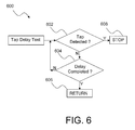
- FIG. 6 is a flow chart of a tap delay testing routine used in conjunction with the flow chart of FIG. 5 .
- the present subject matter is particularly concerned with the use of accelerometer to provide improved removal and inversion tamper detection as well as to implement tap switch feature functionality in electric meters.
- FIG. 1 schematically illustrates an electric meter 100 incorporating aspects of the present technology.
- a linear accelerometer sensor may be incorporated in the register of electric meter 100 .
- this device may correspond to a micro-electronic mechanical sensor (MEMS) capable of detecting motion in three planes.
- MEMS micro-electronic mechanical sensor
- the meter firmware is able to detect removal and inversion with equal or better accuracy than the mechanical sensors previously employed for acceleration detection.
- new tamper features are possible that will add functional capabilities and value to Meter Data Management (MDM) applications for tamper detection and reporting.
- MDM Meter Data Management
- another important aspect to the present technology is the ability to invoke alternate display sequences without the addition of any mechanical hardware or cost to the product.
- Accelerations along three axes, X, Y and Z shown in FIG. 1 may be measured by a low-cost accelerometer.
- the accelerometer may be an LIS331DL, from ST Microelectronics configured to measure accelerations in the X, Y, and Z axes using a data rate of 100 Hz and a steady-state value along each axis between ⁇ 55 and +55 where the maximum steady-state value of +55 occurs when the axis vertically points up and the minimum steady-state value ⁇ 55 occurs when the axis vertically points down.
- the meter register may be configured to request acceleration data from the accelerometer via the accelerometer's digital interface with a 400 KHz clock rate. Calibration data may be stored inside the accelerometer in a nonvolatile memory so that the accelerometer calibrates itself by restoring the calibration data each time the meter is powered on.
- the highest priority task in the electric meter register is configured to wait for signaled semaphores, i.e., control flags, which include an accelerometer semaphore.
- An interrupt timer may be configured to fire every twenty milliseconds to signal the accelerometer semaphore.
- a task detects the signaled accelerometer semaphore, it requests data from the accelerometer and checks the absolute acceleration changes on three axes for the removal tamper and tap detections.
- the accelerometer data output may be re-enabled every minute to avoid false data readings.
- the accelerometer may be re-calibrated every thirty seconds to ensure that the accelerometer works properly.
- inversion tamper detection is simplified through the use of a MEMS accelerometer device.
- the unit is inverted so that the combination of a positive reading and power-up can then be interpreted as an inversion tamper.
- the meter is inversely installed, the X axis should point down to the earth and the steady-state acceleration value along the X axis should be non-negative. Therefore, inversion tamper detection should be implemented by comparing the acceleration value along the X axis against a configured threshold set to a small positive value.
- the acceleration values should be sampled with certain requirements as illustrated in flow chart 200 of FIG. 2 .
- the electric meter register reads the acceleration values from accelerometer 204 along the three axes every twenty milliseconds as determined by timer 206 and puts these values in individual X, Y, Z data buffers 210 .
- the register verifies that each acceleration value in each buffer is close to the values of its neighbors at step 212 . If any one of them is not, all buffer data are discarded and a new set of samples for each buffer is read. This process repeats until the data in each buffer are close to one another, i.e., the accelerometer has reached steady state. This method ensures that the accelerometer acquires reliable initial acceleration values that are important to removal tamper and tap detections.
- the average value on each axis is calculated (step 214 ) and the average value on the X axis is compared to the inversion tamper threshold (step 216 ). If the average value is greater than or equal to the threshold, an inversion tamper is considered to have been detected and an inversion tamper event may then be recorded and a corresponding alarm 218 sent to, for example, an AMR data Collect Engine, or other appropriate location(s). After that, the average value along each axis is used to set as its initial acceleration value (step 220 ), which will be used for the detections of removal tamper and tap.
- meter firmware was typically limited to detection of a state change of the mechanical sensor.
- mechanical sensors correspond to a switch that changes state when tilted beyond a pre-determined angle as dictated by the mechanical design of the sensor.
- mechanical sensors were designed to provide such state change if the product was tilted greater than, for example, 20 degrees from vertical.
- electric meters are not always mounted exactly vertical. In fact, they can often be mounted very close to or greater than the 20 degree position. This can lead to false tampers that result in wasted time and effort to visit a meter that is simply mounted at an angle. If there are too many false tampers in an AMR/AMI deployment, the feature becomes useless and/or counterproductive due to the overwhelming number of false alarms.
- Detection of a removal tamper and of a tap are similar because both are based on acceleration changes. However, it is important that a removal tamper should not be detected when the meter is simply tapped. It is also preferred not to detect a tap during a removal tamper. Therefore, from a design point of view, it is very important to distinguish such two events/functions.
- an electric meter has two degrees of freedom when installed in a matching socket; one is a movement along the Z axis and the other is the rotation around the Y axis.
- the electric meter per present subject matter preferably is configured to monitor acceleration changes along the X and Z axes for the removal tamper detection.
- the tap operation should be performed along the Y axis such that most acceleration changes along the Y axis is much larger than most acceleration changes along the X and Z axes when the meter is tapped. Therefore, per present subject matter, the meter is preferably configured to check the acceleration change along the Y axis for tap detection.
- the MEMS accelerometer sensor provides a digital reading of the force being applied in three axes. When at equilibrium, as an electric meter should be in normal use, the digital reading will be unchanging. Tamper detection is achieved in accordance with present technology as illustrated in the exemplary embodiment of present flow chart 300 of FIG. 3 .
- the electric meter takes reference readings of all three axes when the product is installed and the readings are unchanging. Such step corresponds generally to step 220 illustrated in FIG. 2 .
- the electric meter stores such readings (step 304 ) in an on board memory and continues to monitor the sensor (step 306 ) for a change from the stored references (step 308 ).
- a potential removal condition 312 is detected.
- the assumed amount may correspond to the equivalent of 20° as previously used with mechanical type switches, or some other amount of tilt may be used.
- power-down 314 such condition can be interpreted as a removal tamper 316 .
- a moving average filter may be used to calculate the average acceleration change that are used for detections.
- the average acceleration change for the removal detection may be computed according to Equation (1):
- ⁇ ⁇ ⁇ XZ _ 2 ⁇ N 1 ( 1 )
- ⁇ X is the acceleration change along the X axis with respect to its initial value
- ⁇ Z is the acceleration change along the Z axis with respect to its initial value
- ⁇ XZ is the average value of the most recent N 1 number of absolute acceleration changes along X and Z axes.
- the sampling number N 1 is set to ten because most of the largest acceleration changes along the X and Z axes normally occur within 200 milliseconds during a tampering event.
- Equation (2) The average acceleration change for the tap detection is calculated according to Equation (2) as:
- ⁇ ⁇ ⁇ Y _ ⁇ ⁇ ⁇ ⁇ ⁇ Y ⁇ N 2 - n N 2 ( 2 )
- ⁇ Y is the acceleration change along the Y axis with respect to its initial value
- ⁇ Y is the average value of the most recent N 2 number of absolute acceleration changes along the Y axis.
- the sampling number N 2 is set to five because most of the largest acceleration changes along the Y axis normally occur within 100 milliseconds of each tap.
- a moving average filter makes the detections more tolerant of sporadically large acceleration changes. For example, if there is no vibration during the tampering, the average acceleration change ⁇ Y during the removal tamper is typically smaller than the average acceleration change ⁇ XZ . If the meter is tapped properly, the average acceleration change ⁇ XZ is always smaller than the average acceleration change ⁇ Y . Thus, the average acceleration changes are very suitable for the removal tamper and tap detections.
- the acceleration values along three axes are polled every twenty milliseconds and the moving average filter calculates the average acceleration change ⁇ XZ after each poll. If the average value is greater than or equal to the removal tamper threshold, a flag is set to indicate that a potential removal tamper has been detected.
- the meter checks for power down for a period of time. In an exemplary configuration, such may be for ten seconds. If power down does not occur within the predetermined period, the meter disregards such tamper and continues to the next detection. If the power goes away within the predetermined period, the meter reports a removal tamper and increments a removal tamper counter. A removal tamper event is then recorded and a corresponding alarm is sent to the AMR Collect Engine.
- tap detection is implemented in accordance with flow chart 400 by monitoring the average acceleration change along the Y axis.
- tap reference readings are taken (step 402 ) and stored (step 404 ) wherein the tap reference generally corresponds, as did with reference to step 302 of FIG. 3 , to the initial values of step 220 in FIG. 2 .
- the accelerometer is read (step 406 ) and an average is computed (step 408 ) at predetermined intervals using a moving average filter.
- the predetermined intervals may correspond to every twenty milliseconds.
- the average value is next compared (step 410 ) with a predetermined tap threshold, and a potential tap is detected (step 412 ). If the average acceleration change along the Y axis exceeds the tap threshold and falls below the threshold within a second predetermined time period (step 414 ), a tap (step 416 ) is recognized as having occurred.
- the second predetermined time period may be 400 milliseconds.
- alternate display sequences as well as the more traditional display options and toolbox features can be implemented and controlled by use of tap sequences, for example, “tap-tap” or “tap-tap-tap” on the face of the meter.
- tap sequences for example, “tap-tap” or “tap-tap-tap” on the face of the meter.
- Such tapping sequences have the clear advantage over prior implementations in that no additional switches or magnets are required to control such features.
- different tap sequences may be employed to activate different function in various electric meter implementations or in the same electric meter.
- certain electric meters may support both double-tap and triple-tap implementations wherein the double-tap may be used to invoke an alternate display sequence while the triple-tap may be used to invoke a diagnostic display sequence for advanced polyphase meters.
- timing constraints may be introduced into the detections of double and triple-taps. For example, a double-tap may be detected only if the second tap does not occur within two seconds but occurs within eight seconds after the first tap. Similarly, a triple-tap may be detected only if the third tap does not occur within two seconds but eight seconds after the second tap.
- the user is instructed to wait (step 504 ) until the electric meter display shows a “rdy” message (step 506 ), which means that the meter is ready for the user to apply a second tap.
- the initial waiting period may be set to about two seconds which is enforced by way of a tap delay test as illustrated in FIG. 6 .
- tap delay test 600 is conducted when in step 602 monitoring is conducted to determine whether a tap has occurred. If no tap is detected a determination is made in step 604 as to whether a time period has expired. In an exemplary configuration, such time period may be set to two seconds.
- the routine returns (step 606 ) to the next step in the flow chart of FIG. 5 .
- the electric meter display shows a “rdy” message (step 506 ), which means that the meter is ready for the user to apply a second tap (step 510 ).
- a timer (step 512 ) associated with the display may then be configured to display a count down (step 508 ) to inform the user how much time is left before the next tap must be entered to have the meter recognize a potential double tap (step 514 ).
- such may correspond to a countdown from six to zero to indicate that the user is required to tap the meter again within six seconds to have a double tap detected by the meter.
- a double-tap may be used to invoke an alternate display sequence.
- the alternate display sequence can be programmed with any display quantities the utility desires for diagnostic purposes. For example, for troubleshooting purposes, the alternate display sequence can be much longer and have many more informational displays than the normal display sequence.
- the meter preferably may then re-enter the tap delay test (step 504 ′). If the user taps (step 516 ) the meter during another predetermined time period (for example, two seconds after the second tap), the meter cancels all previous taps and performs nothing. If the user does not tap the meter during the “rdy” display period (step 518 ), a double-tap 520 is confirmed, and the meter starts showing an alternate display sequence.
- a third tap 522 is considered to have occurred. If no further valid tap (steps 504 ′′ and 524 ) is detected during the “rdy” period (step 526 ), a triple-tap 528 is confirmed to have occurred and for certain meters (for example, an advanced polyphase meter), the meter invokes a diagnostic display sequence. Otherwise, if another tap is detected after the third tap, the meter is configured to cancel all taps and performs nothing.
- toolbox and site-scan diagnostic quantities can be programmed into the alternate display sequence, it is desirable to have a dedicated set of displays for the user of such quantities.
- a triple-tap may be used to invoke the diagnostic display sequence in advanced polyphase installations. When the triple-tap is detected, the same diagnostic display sequence that has been previously available in prior electric meters may be displayed.
- default settings may be diagnostics-enabled and manual display timeout set to 60 seconds.
- the meter may be configured such that a subsequent single-tap on the front of the meter will put the display in a manual scroll mode where it will remain until the end of the display sequence or a timeout, whichever comes first.
- the length of time for timeout may be programmable in seconds (for example, ranging from 1 to 65535), with a setting of zero configured to disable the manual scroll feature and the timeout.
- the sensitivity of the tap detection can be controlled through firmware. It is desirable to set the sensitivity such that false taps are not detected and also such that unnecessary force is not needed to invoke the desired feature.
- the sensitivity of the tap feature may be programmable to allow for adjustments while installed.
- an interrupt wakeup mechanism is provided.
- the accelerometer is configured to generate a wakeup interrupt once the acceleration magnitude along the X axis exceeds a wakeup threshold. Because the acceleration along the X axis changes during both removal and tap, the wakeup threshold preferably should be set to some value slightly above the magnitude of the initial acceleration along the X axis.
- the register normally does not request the data from the accelerometer and the I2C communication is idle.
- a wakeup interrupt from the accelerometer informs the register of potential tamper or tap activities.
- the register then sets the wakeup flag.
- An interrupt service routine checks this flag periodically. In an exemplary configuration this may be every twenty milliseconds. When it detects that the flag has been set, it allows the register to start periodically polling the data from the accelerometer and checks the acceleration changes along three axes for the detection of removal tamper or tap.
- the wakeup interrupt is disabled during the polling period.
- the polling period may be configured to last for some short time period, for example, ten minutes.
- the register stops the data request and re-enables the wakeup interrupt for future detections. However, if the register is either checking for power down or during the tapping process when the polling times out, the register does not stop the data polling until both the power down check and the tapping operation are complete. After the polling, the register samples steady state data every 20 milliseconds for another ten times to refill all buffers. If the meter is not in steady state during this sampling time, the wakeup interrupt will be triggered again. When the register completes the sampling of steady state buffer data, it stops the polling and I2C communication goes idle until the next wakeup occurs.
- the meter's angles of installation allow the utility to not only keep track of the socket condition, but also determine potential tampering by reviewing daily angle data. With the use of accelerometer in selected meters, it is feasible to obtain angles of installation.
- the angles of installation of X, Y and Z axes with respect to the earth ground are calculated by equations (3), (4) and (5), respectively:
- the utility can request two angle data from the meter from day to day: reference angles and current angles.
- the reference angles of installation are immediately calculated upon power up after the inversion tamper detection is complete.
- Current angles of installation are computed upon request and the meter must be in steady state when current angles are requested. Otherwise, no data should be returned. Once the utility acquires these daily data, potential tampering can be determined if the angle difference on any axis is not reasonably constant.
Abstract
Description
where ΔX is the acceleration change along the X axis with respect to its initial value, ΔZ is the acceleration change along the Z axis with respect to its initial value, and
where ΔY is the acceleration change along the Y axis with respect to its initial value,
φ, ρ and θ are the tilt angles of X, Y and Z axes, respectively; Accx, Accy and Accz are acceleration values along X, Y and Z axes, respectively.
Claims (15)
Priority Applications (6)
| Application Number | Priority Date | Filing Date | Title |
|---|---|---|---|
| US12/880,339 US8322215B2 (en) | 2010-09-13 | 2010-09-13 | Accelerometer based removal and inversion tamper detection and tap switch feature |
| PCT/US2011/051181 WO2012037010A1 (en) | 2010-09-13 | 2011-09-12 | Accelerometer based removal and inversion tamper detection and tap switch feature |
| BR112013005981A BR112013005981A2 (en) | 2010-09-13 | 2011-09-12 | inversion tamper detection and accelerometer-based removal and beat switching feature |
| MX2013002818A MX2013002818A (en) | 2010-09-13 | 2011-09-12 | Accelerometer based removal and inversion tamper detection and tap switch feature. |
| SG2013018148A SG188962A1 (en) | 2010-09-13 | 2011-09-12 | Accelerometer based removal and inversion tamper detection and tap switch feature |
| EP11825731.0A EP2617019A4 (en) | 2010-09-13 | 2011-09-12 | Accelerometer based removal and inversion tamper detection and tap switch feature |
Applications Claiming Priority (1)
| Application Number | Priority Date | Filing Date | Title |
|---|---|---|---|
| US12/880,339 US8322215B2 (en) | 2010-09-13 | 2010-09-13 | Accelerometer based removal and inversion tamper detection and tap switch feature |
Publications (2)
| Publication Number | Publication Date |
|---|---|
| US20120060606A1 US20120060606A1 (en) | 2012-03-15 |
| US8322215B2 true US8322215B2 (en) | 2012-12-04 |
Family
ID=45805344
Family Applications (1)
| Application Number | Title | Priority Date | Filing Date |
|---|---|---|---|
| US12/880,339 Active 2031-06-23 US8322215B2 (en) | 2010-09-13 | 2010-09-13 | Accelerometer based removal and inversion tamper detection and tap switch feature |
Country Status (6)
| Country | Link |
|---|---|
| US (1) | US8322215B2 (en) |
| EP (1) | EP2617019A4 (en) |
| BR (1) | BR112013005981A2 (en) |
| MX (1) | MX2013002818A (en) |
| SG (1) | SG188962A1 (en) |
| WO (1) | WO2012037010A1 (en) |
Cited By (25)
| Publication number | Priority date | Publication date | Assignee | Title |
|---|---|---|---|---|
| US20120242498A1 (en) * | 2011-03-21 | 2012-09-27 | General Electric Company | User acknowledgement device in electronic utility meter |
| US20130110426A1 (en) * | 2011-11-02 | 2013-05-02 | General Electric Company | Energy meter interface system and method |
| US8979398B2 (en) | 2013-04-16 | 2015-03-17 | Microsoft Technology Licensing, Llc | Wearable camera |
| US9066007B2 (en) | 2013-04-26 | 2015-06-23 | Skype | Camera tap switch |
| US9282244B2 (en) | 2013-03-14 | 2016-03-08 | Microsoft Technology Licensing, Llc | Camera non-touch switch |
| US9451178B2 (en) | 2014-05-22 | 2016-09-20 | Microsoft Technology Licensing, Llc | Automatic insertion of video into a photo story |
| US9503644B2 (en) | 2014-05-22 | 2016-11-22 | Microsoft Technology Licensing, Llc | Using image properties for processing and editing of multiple resolution images |
| US9762980B2 (en) | 2014-09-26 | 2017-09-12 | Mueller International, Llc | High output integrated utility meter reporting system |
| US9918145B2 (en) | 2014-09-26 | 2018-03-13 | Mueller International, Llc | High output integrated utility meter reporting system |
| US10690519B2 (en) | 2018-02-23 | 2020-06-23 | Landis+Gyr Innovations, Inc. | Meter reading sensor using TMR and hall effect sensors |
| US10750116B2 (en) | 2014-05-22 | 2020-08-18 | Microsoft Technology Licensing, Llc | Automatically curating video to fit display time |
| US10788542B2 (en) | 2017-09-28 | 2020-09-29 | Landis+Gyr Llc | Detection of deteriorated electrical connections in a meter using temperature sensing and time variable thresholds |
| US10908198B2 (en) | 2017-08-07 | 2021-02-02 | Landis+Gyr Innovations, Inc. | Determining meter phase using interval voltage measurements |
| US10955491B2 (en) | 2015-10-30 | 2021-03-23 | Landis+Gyr, Inc. | Method for detecting a meter maintenance condition using winding resistance |
| US11183878B2 (en) | 2017-08-07 | 2021-11-23 | Landis+Gyr Innovations, Inc. | Maintaining connectivity information for meters and transformers located in a power distribution network |
| US11226357B2 (en) | 2019-09-27 | 2022-01-18 | Landis+Gyr Innovations, Inc. | Electrical arc detection for electric meter socket connections |
| US11245260B2 (en) | 2020-02-25 | 2022-02-08 | Landis+Gyr Innovations, Inc. | Automatic discovery of electrical supply network topology and phase |
| US11359934B2 (en) | 2020-03-24 | 2022-06-14 | Landis+Gyr Innovations, Inc. | Variable rate monitoring in flow-based metering systems |
| US11385074B2 (en) | 2020-03-18 | 2022-07-12 | Landis+Gyr Innovations, Inc. | Programming electric meter global positioning system coordinates using smart device |
| US11429401B2 (en) * | 2020-03-04 | 2022-08-30 | Landis+Gyr Innovations, Inc. | Navigating a user interface of a utility meter with touch-based interactions |
| US11515725B2 (en) | 2020-09-21 | 2022-11-29 | Landis+Gyr Innovations, Inc. | Autonomous topology validation for electrical supply network |
| US11536754B2 (en) | 2019-08-15 | 2022-12-27 | Landis+Gyr Innovations, Inc. | Electricity meter with fault tolerant power supply |
| US11536745B2 (en) | 2020-03-18 | 2022-12-27 | Landis+Gyr Innovations, Inc. | Electric meter installation issue detection based on orientation change |
| US11646602B2 (en) | 2020-03-11 | 2023-05-09 | Landis+Gyr Innovations, Inc. | Topology and phase detection for electrical supply network |
| US11709074B2 (en) | 2021-01-07 | 2023-07-25 | Honeywell International Inc. | System and method for improved accuracy of detecting meter removal or physical tampering |
Families Citing this family (10)
| Publication number | Priority date | Publication date | Assignee | Title |
|---|---|---|---|---|
| EP2541614A4 (en) * | 2010-02-24 | 2015-11-04 | Kaneka Corp | Thin film photoelectric conversion device and process for production thereof |
| CN104240433A (en) * | 2013-06-08 | 2014-12-24 | 浙江大华技术股份有限公司 | Camera monitoring alarm method and device |
| US20160351028A1 (en) * | 2016-04-12 | 2016-12-01 | Neptune Technology Group Inc. | Tamper Detection In Utility Meters |
| US10282621B2 (en) * | 2016-07-09 | 2019-05-07 | Grabango Co. | Remote state following device |
| SG11201901332TA (en) * | 2016-08-17 | 2019-03-28 | Arnon MAMAN | Meter reading device and system |
| WO2018071904A1 (en) * | 2016-10-14 | 2018-04-19 | Pacific Gas And Electric Company | Smart energy and data/information metering system and method |
| US10916815B2 (en) * | 2018-03-22 | 2021-02-09 | Sensus Spectrum, Llc | Battery orientation system |
| US11688923B2 (en) | 2020-12-04 | 2023-06-27 | Honeywell International Inc. | LTE antenna optimized for North American electricity meters |
| US20220318589A1 (en) * | 2021-03-31 | 2022-10-06 | Paul Abner | Methods and systems of a tamper-evident seal |
| US11860194B2 (en) * | 2021-05-13 | 2024-01-02 | Honeywell International Inc. | Socket-jaw protection module for a meter |
Citations (10)
| Publication number | Priority date | Publication date | Assignee | Title |
|---|---|---|---|---|
| US2784501A (en) * | 1952-06-02 | 1957-03-12 | Curtiss Wright Corp | Apparatus for simulating flight conditions of high speed aircraft |
| US5473322A (en) | 1992-07-24 | 1995-12-05 | Schlumberger Industries, Inc. | Apparatus and method for sensing tampering with a utility meter |
| US5910774A (en) | 1996-09-18 | 1999-06-08 | Itron, Inc. | Sensor for count and tamper detection |
| US6232886B1 (en) | 1998-12-23 | 2001-05-15 | Schlumberger Resource Management Services, Inc. | Method and apparatus for indicating meter tampering |
| US6852935B2 (en) | 2002-10-30 | 2005-02-08 | Itron, Inc. | Tilt switch |
| US20070103334A1 (en) | 2005-11-09 | 2007-05-10 | Distribution Control Systems, Inc. | Tamper detection apparatus for electrical meters |
| US7453373B2 (en) | 2004-10-29 | 2008-11-18 | Itron, Inc. | Integrated meter module and utility metering system |
| US7495555B2 (en) | 2002-07-31 | 2009-02-24 | Itron, Inc. | Magnetic field sensing for tamper identification |
| US20090133499A1 (en) | 2007-11-28 | 2009-05-28 | International Business Machines Corporation | Accelerometer Module for Use With A Touch Sensitive Device |
| US20100256947A1 (en) * | 2009-03-30 | 2010-10-07 | Dong Yoon Kim | Directional tap detection algorithm using an accelerometer |
-
2010
- 2010-09-13 US US12/880,339 patent/US8322215B2/en active Active
-
2011
- 2011-09-12 EP EP11825731.0A patent/EP2617019A4/en not_active Withdrawn
- 2011-09-12 MX MX2013002818A patent/MX2013002818A/en active IP Right Grant
- 2011-09-12 WO PCT/US2011/051181 patent/WO2012037010A1/en active Application Filing
- 2011-09-12 SG SG2013018148A patent/SG188962A1/en unknown
- 2011-09-12 BR BR112013005981A patent/BR112013005981A2/en not_active Application Discontinuation
Patent Citations (10)
| Publication number | Priority date | Publication date | Assignee | Title |
|---|---|---|---|---|
| US2784501A (en) * | 1952-06-02 | 1957-03-12 | Curtiss Wright Corp | Apparatus for simulating flight conditions of high speed aircraft |
| US5473322A (en) | 1992-07-24 | 1995-12-05 | Schlumberger Industries, Inc. | Apparatus and method for sensing tampering with a utility meter |
| US5910774A (en) | 1996-09-18 | 1999-06-08 | Itron, Inc. | Sensor for count and tamper detection |
| US6232886B1 (en) | 1998-12-23 | 2001-05-15 | Schlumberger Resource Management Services, Inc. | Method and apparatus for indicating meter tampering |
| US7495555B2 (en) | 2002-07-31 | 2009-02-24 | Itron, Inc. | Magnetic field sensing for tamper identification |
| US6852935B2 (en) | 2002-10-30 | 2005-02-08 | Itron, Inc. | Tilt switch |
| US7453373B2 (en) | 2004-10-29 | 2008-11-18 | Itron, Inc. | Integrated meter module and utility metering system |
| US20070103334A1 (en) | 2005-11-09 | 2007-05-10 | Distribution Control Systems, Inc. | Tamper detection apparatus for electrical meters |
| US20090133499A1 (en) | 2007-11-28 | 2009-05-28 | International Business Machines Corporation | Accelerometer Module for Use With A Touch Sensitive Device |
| US20100256947A1 (en) * | 2009-03-30 | 2010-10-07 | Dong Yoon Kim | Directional tap detection algorithm using an accelerometer |
Non-Patent Citations (2)
| Title |
|---|
| PCT International Search Report for PCT International Application No. PCT/US2011/051181, search completed Dec. 14, 2011, mailed Dec. 23, 2011. |
| PCT Written Opinion of the International Searching Authority for PCT International Application No. PCT/US2011/051181, opinion completed Dec. 14, 2011, date of mailing Dec. 23, 2011. |
Cited By (31)
| Publication number | Priority date | Publication date | Assignee | Title |
|---|---|---|---|---|
| US20120242498A1 (en) * | 2011-03-21 | 2012-09-27 | General Electric Company | User acknowledgement device in electronic utility meter |
| US20130110426A1 (en) * | 2011-11-02 | 2013-05-02 | General Electric Company | Energy meter interface system and method |
| US9516227B2 (en) | 2013-03-14 | 2016-12-06 | Microsoft Technology Licensing, Llc | Camera non-touch switch |
| US9282244B2 (en) | 2013-03-14 | 2016-03-08 | Microsoft Technology Licensing, Llc | Camera non-touch switch |
| US8979398B2 (en) | 2013-04-16 | 2015-03-17 | Microsoft Technology Licensing, Llc | Wearable camera |
| US9066007B2 (en) | 2013-04-26 | 2015-06-23 | Skype | Camera tap switch |
| US9444996B2 (en) | 2013-04-26 | 2016-09-13 | Microsoft Technology Licensing, Llc | Camera tap switch |
| US9451178B2 (en) | 2014-05-22 | 2016-09-20 | Microsoft Technology Licensing, Llc | Automatic insertion of video into a photo story |
| US9503644B2 (en) | 2014-05-22 | 2016-11-22 | Microsoft Technology Licensing, Llc | Using image properties for processing and editing of multiple resolution images |
| US11184580B2 (en) | 2014-05-22 | 2021-11-23 | Microsoft Technology Licensing, Llc | Automatically curating video to fit display time |
| US10750116B2 (en) | 2014-05-22 | 2020-08-18 | Microsoft Technology Licensing, Llc | Automatically curating video to fit display time |
| US9762980B2 (en) | 2014-09-26 | 2017-09-12 | Mueller International, Llc | High output integrated utility meter reporting system |
| US9918145B2 (en) | 2014-09-26 | 2018-03-13 | Mueller International, Llc | High output integrated utility meter reporting system |
| US10955491B2 (en) | 2015-10-30 | 2021-03-23 | Landis+Gyr, Inc. | Method for detecting a meter maintenance condition using winding resistance |
| US10908198B2 (en) | 2017-08-07 | 2021-02-02 | Landis+Gyr Innovations, Inc. | Determining meter phase using interval voltage measurements |
| US11183878B2 (en) | 2017-08-07 | 2021-11-23 | Landis+Gyr Innovations, Inc. | Maintaining connectivity information for meters and transformers located in a power distribution network |
| US11916380B2 (en) | 2017-08-07 | 2024-02-27 | Landis+Gyr Technology, Inc. | Maintaining connectivity information for meters and transformers located in a power distribution network |
| US10788542B2 (en) | 2017-09-28 | 2020-09-29 | Landis+Gyr Llc | Detection of deteriorated electrical connections in a meter using temperature sensing and time variable thresholds |
| US10690519B2 (en) | 2018-02-23 | 2020-06-23 | Landis+Gyr Innovations, Inc. | Meter reading sensor using TMR and hall effect sensors |
| US11536754B2 (en) | 2019-08-15 | 2022-12-27 | Landis+Gyr Innovations, Inc. | Electricity meter with fault tolerant power supply |
| US11226357B2 (en) | 2019-09-27 | 2022-01-18 | Landis+Gyr Innovations, Inc. | Electrical arc detection for electric meter socket connections |
| US11245260B2 (en) | 2020-02-25 | 2022-02-08 | Landis+Gyr Innovations, Inc. | Automatic discovery of electrical supply network topology and phase |
| US11721977B2 (en) | 2020-02-25 | 2023-08-08 | Landis+Gyr Innovations, Inc. | Automatic discovery of electrical supply network topology and phase |
| US11429401B2 (en) * | 2020-03-04 | 2022-08-30 | Landis+Gyr Innovations, Inc. | Navigating a user interface of a utility meter with touch-based interactions |
| US11646602B2 (en) | 2020-03-11 | 2023-05-09 | Landis+Gyr Innovations, Inc. | Topology and phase detection for electrical supply network |
| US11385074B2 (en) | 2020-03-18 | 2022-07-12 | Landis+Gyr Innovations, Inc. | Programming electric meter global positioning system coordinates using smart device |
| US11536745B2 (en) | 2020-03-18 | 2022-12-27 | Landis+Gyr Innovations, Inc. | Electric meter installation issue detection based on orientation change |
| US11359934B2 (en) | 2020-03-24 | 2022-06-14 | Landis+Gyr Innovations, Inc. | Variable rate monitoring in flow-based metering systems |
| US11515725B2 (en) | 2020-09-21 | 2022-11-29 | Landis+Gyr Innovations, Inc. | Autonomous topology validation for electrical supply network |
| US11735954B2 (en) | 2020-09-21 | 2023-08-22 | Landis+Gyr Innovations, Inc. | Autonomous topology validation for electrical supply network |
| US11709074B2 (en) | 2021-01-07 | 2023-07-25 | Honeywell International Inc. | System and method for improved accuracy of detecting meter removal or physical tampering |
Also Published As
| Publication number | Publication date |
|---|---|
| SG188962A1 (en) | 2013-05-31 |
| US20120060606A1 (en) | 2012-03-15 |
| EP2617019A1 (en) | 2013-07-24 |
| BR112013005981A2 (en) | 2016-06-07 |
| EP2617019A4 (en) | 2017-01-11 |
| WO2012037010A1 (en) | 2012-03-22 |
| MX2013002818A (en) | 2013-04-09 |
Similar Documents
| Publication | Publication Date | Title |
|---|---|---|
| US8322215B2 (en) | Accelerometer based removal and inversion tamper detection and tap switch feature | |
| US9671254B2 (en) | Magnetic sensing to detect tampering with a utility meter | |
| US7936163B2 (en) | Method and system for detecting electricity theft | |
| WO2016043861A1 (en) | Reverse flow detection and annunciation | |
| US7400265B2 (en) | Remotely readable gas meter and method of using the same | |
| KR100844853B1 (en) | Electronic water service meter and the control method | |
| JP2013044739A (en) | Inclination change measuring sensor network device and inclination change measuring sensor network system | |
| CA2963898A1 (en) | Tamper detection in utility meters | |
| US20090284392A1 (en) | Remotely readable gas meter and method of using the same | |
| US11428833B2 (en) | Earthquake sensing module and earthquake sensing system | |
| JP5849189B2 (en) | Wireless device for automatic meter reading | |
| JP4108443B2 (en) | Positioning device and method for diagnosing installation state of positioning device | |
| CN203422791U (en) | Anti-demounting intelligent gas meter | |
| DK180077B1 (en) | Road Equipment Monitoring Device | |
| KR101638856B1 (en) | Security devices for digital water meter | |
| JP2010038716A (en) | Measurement output apparatus and electric energy measuring system | |
| US20120203498A1 (en) | Tamper detection with tilt sensors | |
| CN204007758U (en) | Flow detector | |
| CN100507463C (en) | Electric water meter | |
| JP2004102995A (en) | Super-power-saving type meter | |
| KR101342691B1 (en) | Remote inspection device of the flow meter, trouble decision device and method using that remote inspection device | |
| CN102506228A (en) | Faucet monitoring device, faucet comprising same and monitoring method | |
| JP2019007736A (en) | Fastener with sensor and loose detection system | |
| KR102206522B1 (en) | System for Detecting Building in Danger of Collapsing Based on Temperature Change | |
| JP4526370B2 (en) | Meter and meter adapter |
Legal Events
| Date | Code | Title | Description |
|---|---|---|---|
| AS | Assignment |
Owner name: ITRON, INC., WASHINGTON Free format text: ASSIGNMENT OF ASSIGNORS INTEREST;ASSIGNORS:LAKICH, DANIEL M.;HUANG, JIANGYANG;SIGNING DATES FROM 20100923 TO 20100928;REEL/FRAME:025119/0682 |
|
| AS | Assignment |
Owner name: WELLS FARGO BANK, NATIONAL ASSOCIATION, WASHINGTON Free format text: SECURITY AGREEMENT;ASSIGNOR:ITRON, INC.;REEL/FRAME:026761/0069 Effective date: 20110805 |
|
| STCF | Information on status: patent grant |
Free format text: PATENTED CASE |
|
| FPAY | Fee payment |
Year of fee payment: 4 |
|
| AS | Assignment |
Owner name: WELLS FARGO BANK, NATIONAL ASSOCIATION, NORTH CAROLINA Free format text: SECURITY INTEREST;ASSIGNORS:ITRON, INC.;ITRON NETWORKED SOLUTIONS, INC.;REEL/FRAME:045017/0893 Effective date: 20180105 Owner name: WELLS FARGO BANK, NATIONAL ASSOCIATION, NORTH CARO Free format text: SECURITY INTEREST;ASSIGNORS:ITRON, INC.;ITRON NETWORKED SOLUTIONS, INC.;REEL/FRAME:045017/0893 Effective date: 20180105 |
|
| MAFP | Maintenance fee payment |
Free format text: PAYMENT OF MAINTENANCE FEE, 8TH YEAR, LARGE ENTITY (ORIGINAL EVENT CODE: M1552); ENTITY STATUS OF PATENT OWNER: LARGE ENTITY Year of fee payment: 8 |