US8400142B2 - Linear position sensor with anti-rotation device - Google Patents
Linear position sensor with anti-rotation device Download PDFInfo
- Publication number
- US8400142B2 US8400142B2 US12/592,170 US59217009A US8400142B2 US 8400142 B2 US8400142 B2 US 8400142B2 US 59217009 A US59217009 A US 59217009A US 8400142 B2 US8400142 B2 US 8400142B2
- Authority
- US
- United States
- Prior art keywords
- magnet
- magnet carrier
- rotation
- base
- plate
- Prior art date
- Legal status (The legal status is an assumption and is not a legal conclusion. Google has not performed a legal analysis and makes no representation as to the accuracy of the status listed.)
- Expired - Fee Related, expires
Links
Images


Classifications
-
- G—PHYSICS
- G01—MEASURING; TESTING
- G01D—MEASURING NOT SPECIALLY ADAPTED FOR A SPECIFIC VARIABLE; ARRANGEMENTS FOR MEASURING TWO OR MORE VARIABLES NOT COVERED IN A SINGLE OTHER SUBCLASS; TARIFF METERING APPARATUS; MEASURING OR TESTING NOT OTHERWISE PROVIDED FOR
- G01D3/00—Indicating or recording apparatus with provision for the special purposes referred to in the subgroups
- G01D3/028—Indicating or recording apparatus with provision for the special purposes referred to in the subgroups mitigating undesired influences, e.g. temperature, pressure
-
- G—PHYSICS
- G01—MEASURING; TESTING
- G01D—MEASURING NOT SPECIALLY ADAPTED FOR A SPECIFIC VARIABLE; ARRANGEMENTS FOR MEASURING TWO OR MORE VARIABLES NOT COVERED IN A SINGLE OTHER SUBCLASS; TARIFF METERING APPARATUS; MEASURING OR TESTING NOT OTHERWISE PROVIDED FOR
- G01D5/00—Mechanical means for transferring the output of a sensing member; Means for converting the output of a sensing member to another variable where the form or nature of the sensing member does not constrain the means for converting; Transducers not specially adapted for a specific variable
- G01D5/12—Mechanical means for transferring the output of a sensing member; Means for converting the output of a sensing member to another variable where the form or nature of the sensing member does not constrain the means for converting; Transducers not specially adapted for a specific variable using electric or magnetic means
- G01D5/14—Mechanical means for transferring the output of a sensing member; Means for converting the output of a sensing member to another variable where the form or nature of the sensing member does not constrain the means for converting; Transducers not specially adapted for a specific variable using electric or magnetic means influencing the magnitude of a current or voltage
- G01D5/142—Mechanical means for transferring the output of a sensing member; Means for converting the output of a sensing member to another variable where the form or nature of the sensing member does not constrain the means for converting; Transducers not specially adapted for a specific variable using electric or magnetic means influencing the magnitude of a current or voltage using Hall-effect devices
- G01D5/145—Mechanical means for transferring the output of a sensing member; Means for converting the output of a sensing member to another variable where the form or nature of the sensing member does not constrain the means for converting; Transducers not specially adapted for a specific variable using electric or magnetic means influencing the magnitude of a current or voltage using Hall-effect devices influenced by the relative movement between the Hall device and magnetic fields
-
- G—PHYSICS
- G01—MEASURING; TESTING
- G01B—MEASURING LENGTH, THICKNESS OR SIMILAR LINEAR DIMENSIONS; MEASURING ANGLES; MEASURING AREAS; MEASURING IRREGULARITIES OF SURFACES OR CONTOURS
- G01B7/00—Measuring arrangements characterised by the use of electric or magnetic techniques
- G01B7/14—Measuring arrangements characterised by the use of electric or magnetic techniques for measuring distance or clearance between spaced objects or spaced apertures
-
- G—PHYSICS
- G01—MEASURING; TESTING
- G01D—MEASURING NOT SPECIALLY ADAPTED FOR A SPECIFIC VARIABLE; ARRANGEMENTS FOR MEASURING TWO OR MORE VARIABLES NOT COVERED IN A SINGLE OTHER SUBCLASS; TARIFF METERING APPARATUS; MEASURING OR TESTING NOT OTHERWISE PROVIDED FOR
- G01D11/00—Component parts of measuring arrangements not specially adapted for a specific variable
- G01D11/16—Elements for restraining, or preventing the movement of, parts, e.g. for zeroising
-
- G—PHYSICS
- G01—MEASURING; TESTING
- G01D—MEASURING NOT SPECIALLY ADAPTED FOR A SPECIFIC VARIABLE; ARRANGEMENTS FOR MEASURING TWO OR MORE VARIABLES NOT COVERED IN A SINGLE OTHER SUBCLASS; TARIFF METERING APPARATUS; MEASURING OR TESTING NOT OTHERWISE PROVIDED FOR
- G01D11/00—Component parts of measuring arrangements not specially adapted for a specific variable
- G01D11/24—Housings ; Casings for instruments
- G01D11/245—Housings for sensors
Definitions
- This invention relates in general to linear position sensors and, more specifically, to devices to prevent the rotation of the magnet used in a non-contacting linear position sensor.
- Position sensing is used to electronically monitor the position or movement of a mechanical component.
- the position sensor produces an electrical signal that varies as the position of the component in question varies.
- Electrical position sensors are included in many products. For example, position sensors allow the status of various automotive components to be monitored and controlled electronically.
- a position sensor needs to be accurate, in that it must give an appropriate electrical signal based upon the position measured. If inaccurate, a position sensor may hinder the proper evaluation and control of the position of the component being monitored.
- a position sensor typically be adequately precise in its measurement.
- the precision needed in measuring a position will obviously vary depending upon the particular circumstances of use. For some purposes, only a rough indication of position is necessary; for instance, an indication of whether a valve is mostly open or mostly closed. In other applications, more precise indication of position may be needed.
- a position sensor should also be sufficiently durable for the environment in which it is placed. For example, a position sensor used on an automotive valve may experience almost constant movement while the automobile is in operation. Such a position sensor should be constructed of mechanical and electrical components adequate to allow the sensor to remain sufficiently accurate and precise during its projected lifetime, despite considerable mechanical vibrations and thermal extremes and gradients.
- position sensors were typically of the “contact” variety.
- a contacting position sensor requires physical contact to produce the electrical signal.
- Contacting position sensors typically consist of potentiometers that produce electrical signals which vary as a function of the component's position. Contacting position sensors are generally accurate and precise. Unfortunately, the wear due to contact during movement has limited their durability. Also, the friction resulting from the contact can degrade the operation of the component. Further, water intrusion into a potentiometric sensor can disable the sensor.
- a non-contacting position sensor (“NPS”) does not require physical contact between the signal generator and the sensing element. Instead, an NPS utilizes magnets to generate magnetic fields that vary as a function of position, and devices to detect varying magnetic fields to measure the position of the component to be monitored. Often, a Hall effect device is used to produce an electrical signal that is dependent upon the magnitude and polarity of the magnetic flux incident upon the device. The Hall effect device may be physically attached to the component to be monitored and thus moves relative to the stationary magnet(s) as the component moves. Conversely, the Hall effect device may be stationary with the magnet(s) affixed to the component to be monitored. In either case, the position of the component to be monitored can be determined by the electrical signal produced by the Hall effect device.
- an NPS presents several distinct advantages over the use of a contacting position sensor. Because an NPS does not require physical contact between the signal generator and the sensing element, there is less physical wear during operation, resulting in greater sensor durability. The use of an NPS is also advantageous because the lack of any physical contact between the items being monitored and the sensor itself results in reduced drag.
- NPS While the use of an NPS presents several advantages, there are also several disadvantages that must be overcome in order for an NPS to be a satisfactory position sensor for many applications. Irregularities or imperfections in the magnet can compromise the precision and accuracy of an NPS. The accuracy and precision of an NPS can also be affected by the mechanical vibrations and perturbations likely to be experienced by the sensor which, in turn, can cause the magnet or magnet carrier to rotate. Because there is no physical contact between the item to be monitored and the sensor, it is possible for the magnet or magnet carrier to be knocked out of alignment as a result of such vibrations and perturbations. A misalignment or rotation of the magnet relative to the sensor can result in the measured magnetic field at any particular location not being what it would be in the original alignment. Because the measured magnetic field can be different than that when properly aligned, the perceived position can be inaccurate. Linearity of magnetic field strength and the resulting signal is also a concern.
- the present invention is directed broadly to a linear position sensor which comprises a housing, a magnet carrier located in the housing, a magnet located in the magnet carrier, and several different embodiments of anti-rotation means or devices associated with the magnet carrier for preventing the rotation of the magnet outside of allowable variations in rotational movement and eliminating the risk of undesired magnetic field measurements and incorrect sensor signal outputs.
- the magnet carrier includes a base having at least one receptacle defined therein and the anti-rotation means comprises an anti-rotation plate which is coupled to the housing and the magnet carrier and the magnet carrier includes at least one finger which extends into the receptacle in the base of the magnet carrier to prevent the rotation of the magnet carrier and thus the rotation of the magnet.
- the base of the magnet carrier includes a peripheral edge and the receptacle is defined by a groove formed in the peripheral edge of the magnet carrier.
- the base of the magnet carrier includes a lower surface and the receptacle is defined by a groove formed in the lower surface of the magnet carrier.
- the groove may be a circumferentially extending slot formed in the lower surface of the magnet carrier.
- the base of the magnet carrier includes opposed upper and lower surfaces and the receptacle is defined by a through-hole which extends between the upper and lower surfaces of the magnet carrier.
- the anti-rotation plate includes at least one interior slot formed therein which defines the finger and the finger is adapted to abut and exert a force against the lower surface of the base of the magnet carrier.
- the magnet carrier includes a magnet housing having an interior surface with a key defined by a projection and the anti-rotation means comprises a groove in the magnet.
- the projection in the magnet carrier extends into the groove in the magnet to prevent the rotation of the magnet.
- the projection may be formed in an interior side surface of the magnet housing and the groove may be defined in an exterior side surface of the magnet.
- the projection may be formed in an interior base surface of the magnet housing and the groove may be defined in an exterior bottom surface of the magnet.
- the magnet housing may include at least one prong extending from a peripheral top edge thereof and another groove may be defined in an exterior top surface of the magnet and the prong extends into the groove in the exterior top surface of the magnet.
- FIG. 1 is a part vertical cross-sectional view, part perspective view of a linear position sensor with a first embodiment of a magnet carrier/anti-rotation plate combination or device in accordance with the present invention
- FIG. 2 is an enlarged perspective view of the magnet carrier/anti-rotation plate combination shown in FIG. 1 ;
- FIG. 3 is an enlarged exploded perspective view of the magnet carrier and anti-rotation plate shown in FIGS. 1 and 2 ;
- FIG. 4 is an enlarged broken perspective view of a second embodiment of a magnet carrier/anti-rotation plate combination in accordance with the present invention.
- FIG. 5 is an enlarged vertical cross-sectional view of the magnet carrier/anti-rotation plate embodiment of FIG. 4 coupled to the base in the interior of a linear position sensor as shown in FIG. 1 ;
- FIG. 6 is an enlarged exploded perspective view of the magnet carrier and anti-rotation plate combination shown in FIGS. 4 and 5 ;
- FIG. 7 is an enlarged broken part vertical cross-sectional view, part perspective view of a third embodiment of a magnet carrier/anti-rotation plate combination in accordance with the present invention coupled to the base in the interior of a linear position sensor as shown in FIG. 1 ;
- FIG. 8 is an enlarged exploded perspective view of the magnet carrier and anti-rotation plate shown in FIG. 7 ;
- FIG. 9 is an enlarged bottom perspective view of the magnet carrier/anti-rotation plate combination shown in FIGS. 7 and 8 ;
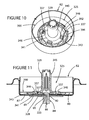
- FIG. 10 is an enlarged top broken perspective view of another embodiment of a magnet carrier/anti-rotation plate combination in accordance with the present invention coupled to the base in the interior of a linear position sensor as shown in FIG. 1 ;
- FIG. 11 is an enlarged vertical cross-sectional view of the magnet carrier/anti-rotation plate combination of FIG. 10 ;
- FIG. 12 is a broken exploded perspective view of the magnet carrier and anti-rotation plate combination of FIG. 10 ;
- FIG. 13 is an enlarged perspective view of yet another magnet carrier/anti-rotation plate combination in accordance with the present invention.
- FIG. 14 is an enlarged broken vertical cross-sectional view of the magnet carrier/anti-rotation plate combination of FIG. 13 coupled to the base in the interior of a linear position sensor as shown in FIG. 1 ;
- FIG. 15 is an enlarged exploded perspective view of the magnet carrier and anti-rotation plate combination shown in FIGS. 13 and 14 ;
- FIG. 16 is an enlarged exploded perspective view of a magnet carrier/anti-rotation magnet combination in accordance with the present invention.
- FIG. 17 is an enlarged horizontal cross-sectional view of the magnet carrier/anti-rotation magnet combination of FIG. 16 with the anti-rotation magnet secured in the magnet carrier;
- FIG. 18 is an enlarged vertical cross-sectional view of another embodiment of a magnet carrier/anti-rotation magnet combination in accordance with the present invention.
- FIG. 19 is an enlarged broken top perspective view of the magnet carrier/anti-rotation magnet combination of FIG. 18 .
- FIGS. 1-3 A first embodiment of an anti-rotation magnet carrier/anti-rotation plate assembly or device or combination 25 in accordance with the present invention is shown in FIGS. 1-3 which comprises an anti-rotation disc or plate 27 and a magnet carrier 29 .
- Anti-rotation disc or plate 27 has a circular solid base 28 , an outer circumferentially extending peripheral edge 31 , a central through-hole or aperture 33 , and a plurality of tabs or fingers 35 and 37 projecting outwardly and upwardly away from the peripheral edge 31 and extending around the base 28 in a spaced-apart, equidistant, and alternating relationship.
- Anti-rotation disc or plate 27 can be stamped from sheet metal.
- the tabs or fingers 35 are wider and shorter than the tabs or fingers 37 .
- Magnet carrier 29 has a generally circular base 41 with a circumferentially extending outer peripheral edge 43 ; a vertical, hollow magnet tube or housing 45 extending generally normally upwardly from a central portion of the base 41 ; and a plurality of receptacles in the form of recesses, grooves, notches, or slots 47 which are formed in the peripheral edge 43 and extend around the base 41 in a spaced-apart, equidistant relationship.
- Magnet carrier 29 may be made from any suitable thermoplastic material.
- Linear position sensor 10 additionally comprises an elongate, generally cylindrically-shaped shaft 84 which extends through the aligned apertures 33 and 85 in the plate 27 and base 80 respectively.
- the shaft 84 includes a head 86 having a width greater than the diameter of the shaft 84 and a circumferential recess or groove defined in the outer surface on the shaft 84 below the head 86 which defines a shoulder 90 spaced from the head 86 .
- the anti-rotation plate 27 and base 80 together with a portion of a membrane 87 located below the base 80 and another plate 89 located below the membrane 87 are sandwiched between the head 86 and the shoulder 90 of shaft 84 to clamp the plate 27 to the base 80 of the cup 82 and keep the plate 27 from moving or rotating relative to the cup 82 .
- magnet carrier 29 is seated over the anti-rotation plate 27 in a relationship wherein the lower face of the base 41 of magnet carrier 29 is seated in abutting relationship against the upper face of the base 28 of anti-rotation plate 27 ; the peripheral edge 43 of the base 41 of magnet carrier 29 is abutted against the interior face of each of the tabs 35 on the base 28 of anti-rotation plate 27 ; and fingers 37 are aligned with the notches 47 .
- the fingers 37 are bent inwardly from their FIG. 3 positions to their crimped FIGS.
- FIGS. 4-6 Another embodiment of anti-rotation assembly 125 in accordance with the present invention is shown in FIGS. 4-6 .
- Anti-rotation assembly 125 comprises an anti-rotation disc or plate 127 and a magnet carrier 129 .
- Anti-rotation disc or plate 127 has a circular solid base or plate 128 , an outer circumferentially extending edge 131 , a central aperture 133 , and a plurality of tabs 137 projecting outwardly and upwardly from the edge 131 of plate 127 and extending around the base 128 in equidistant, spaced-apart relationship.
- the base 128 additionally defines a plurality of interior spaced-apart, equidistant, generally U-shaped slots 130 defining a plurality of circumferentially extending interior raised pre-stressed prongs, tabs, or fingers 132 .
- Anti-rotation disc or plate 129 can be stamped from sheet metal.
- Magnet carrier 129 which may be made from any suitable thermoplastic material, includes a generally circular base 141 having an outer circumferentially extending peripheral edge 143 and a central generally cylindrical, hollow magnet tube or housing 145 extending upwardly from the center of the base 141 .
- anti-rotation disc or plate 127 is seated on the base 80 of the cup 82 in the interior of linear position sensor 10 and the shaft 84 secures the plate 127 against rotational movement relative to the base 80 in the same manner as the plate 27 of anti-rotation assembly 25 , and thus the earlier description with reference to the attachment of the plate 27 of assembly 25 to the base 80 is incorporated herein by reference.
- the bottom face or surface of the base 141 of magnet carrier 129 is seated against the upper face or surface of the base 128 of plate 127 in a relationship wherein the prongs 132 in the base 128 of plate 127 abut against the bottom surface of the base 141 of magnet carrier 129 .
- Tabs 137 on the base 141 of magnet carrier 129 are bent and crimped inwardly into abutting relationship with the top face or surface of the base 141 to secure the base 141 and thus the magnet carrier 129 to the plate 127 , thus preventing the rotation of the magnet carrier 129 relative to the plate 127 and the rotation of magnet 100 ( FIG. 1 ) relative to the sensor 102 ( FIG. 1 ) outside of allowable variations in rotational movement to eliminate the risk of undesired magnetic field measurements and incorrect sensor signal outputs.
- the crimp force exerted by the tabs 137 on the base 141 exerts a downward force against the base 141 which, in turn, causes the raised pre-stressed prongs or tabs 137 on plate 127 to flatten out.
- the pre-stress prongs 137 are also adapted to flex with the thermoplastic material of the base 141 as a result of thermal exposure to reduce the effects of creep and eliminate the rotation of the magnet carrier 129 .
- Anti-rotation assembly 225 comprises an anti-rotation disc or plate 227 and a magnet carrier 229 .
- Anti-rotation disc or plate 227 has a circular base 228 , an outer circumferential peripheral edge 231 , a central aperture 233 , and a plurality of prongs 237 extending outwardly and generally normally upwardly from the peripheral edge 231 .
- prongs 237 extend around the base 228 in an equidistant, spaced-apart relationship.
- Each of the prongs 237 has a pair of sharp points 238 that extend generally normally inwardly from opposed sides of each of the prongs 237 .
- Anti-rotation disc or plate 227 may be stamped from sheet metal.
- Magnet carrier 229 which may be made from any suitable thermoplastic material, has a generally circular base 241 with an outer circumferentially extending peripheral edge 243 ; a vertical, cylindrical, hollow magnet or housing tube 245 extending generally upwardly from a central portion of the top surface or face of the base 241 ; and an annular circumferentially extending interior receptacle in the form of a slot 244 formed and extending into the bottom surface or face of base 241 .
- the plate 227 of anti-rotation assembly 225 is seated on the base 80 of the cup 82 in linear position sensor 10 and is rigidly connected to the shaft 84 of linear position sensor 10 in the same manner as the plate 27 of anti-rotation assembly 25 and thus the earlier description with reference to assembly 25 is incorporated herein by reference.
- the bottom face or surface of the base 241 of magnet carrier 229 is seated against the upper face or surface of the base 228 of the plate 227 in a relationship wherein the prongs 237 on plate 227 are aligned with and extend into respective portions of the slot 244 in the bottom face or surface of the base 241 of magnet carrier 229 .
- the sharp points 238 on each of the prongs 237 have a length which is greater than the width of the slot 244 so that the points 238 wedge into the material of the base 241 upon insertion of the prongs 237 in base 241 to secure the magnet carrier 229 to the plate 227 and prevent the rotation of the magnet carrier 229 relative to the plate 227 which, in turn, prevents the rotation of the magnet 100 ( FIG. 1 ) relative to the sensor 102 ( FIG. 1 ) outside of allowable variations in rotational movement to eliminate the risk of undesired magnetic field measurements and incorrect sensor signal outputs.
- FIGS. 10-12 depict a further embodiment of an anti-rotation assembly 325 in accordance with the present invention which comprises an anti-rotation disc or plate 327 and a magnet carrier 329 .
- Anti-rotation disc or plate 327 has a circular base 328 , an outer peripheral circumferential edge 331 , a central aperture 333 , and a plurality of fingers 337 projecting outwardly and generally normally upwardly from the peripheral edge 331 and extending around the base 328 in an equidistant, spaced-apart relationship.
- Anti-rotation disc or plate 327 may be stamped from sheet metal.
- Magnet carrier 329 which may be made from any suitable thermoplastic material has a generally circular base 341 with an outer peripheral circumferential edge 343 ; a vertical, hollow, cylindrical magnet tube or housing 345 extending normally upwardly from the center of the top surface of the base 341 ; at least one receptacle in the form of a recess, groove, notch, or slot 344 formed in the peripheral edge 343 of base 341 ; and a plurality of interior receptacles in the form of through-holes or openings 346 defined in the base 341 and extending between the top and bottom surfaces thereof.
- Through-holes 346 extend around the base 341 in an equidistant, spaced-apart relationship.
- anti-rotation disc or plate 327 is seated on the base 80 of the cup 82 in linear position sensor 10 and the shaft 84 of linear position sensor 10 couples and secures the plate 327 to the cup 82 in the same manner as described earlier with respect to the plate 27 of anti-rotation assembly 25 , and thus the earlier description with reference to plate 27 is incorporated herein by reference.
- magnet carrier 329 is located and seated in the interior of the cup 82 of linear position sensor 10 in a relationship wherein the bottom face or surface of the base 341 of magnet carrier 329 is seated against the upper face or surface of the base 328 of the plate 327 in a relationship wherein the fingers 337 on plate 327 are aligned with and extend through respective ones of the through-holes 346 defined in the base 329 of magnet carrier 341 to prevent the rotation of the magnet carrier 329 relative to the plate 327 and thus prevent the rotation of magnet 100 ( FIG. 1 ) relative to the sensor 102 ( FIG. 1 ) outside of allowable variations in rotational measurement to eliminate the risk of undesired magnetic field measurements and incorrect sensor signal outputs.
- linear position sensor 10 additionally comprises an annular outer ring 390 including a tab 392 which extends generally normally outwardly and downwardly from an interior peripheral circumferential edge 394 of ring 390 .
- Ring 390 is seated in the cup 82 of linear position sensor 10 in a relationship surrounding and abutting against the top surface of the peripheral circumferential edge 343 of the base 341 of magnet carrier 329 with the tab 392 seated in the groove 344 defined in the edge 342 of the base 341 of magnet carrier 329 to prevent the rotation of the ring 390 relative to the magnet carrier 329 and the cup 82 .
- FIGS. 13-15 depict yet a further embodiment of an anti-rotation assembly 425 in accordance with the present invention which comprises an anti-rotation disc or plate 427 and a magnet carrier 429 .
- Anti-rotation disc or plate 427 has a circular base 428 , an outer peripheral circumferential edge 431 , a central aperture 433 , a plurality of crimp tabs 437 projecting outwardly and upwardly from the peripheral edge 431 , and a plurality of elongate legs 439 also extending outwardly from the peripheral edge 431 .
- the fingers 437 and legs 439 extend around the base 428 in a spaced-apart and alternating equidistant relationship.
- the tabs 437 are shown in FIG. 15 in their uncrimped position and orientation generally normal to the base 428 of plate 427 .
- the legs 439 extend outwardly from the peripheral edge 431 of plate 427 in a relationship generally co-planar with the base 429 .
- Each of the legs 439 includes a distal upturned ear 440 extending generally normally upwardly from the distal end of each of the legs 439 .
- Magnet carrier 429 has a generally circular base 441 with an outer peripheral circumferential edge 443 , and a vertical, hollow, cylindrical magnet tube or housing 445 extending generally normally upwardly from the center of the base 441 .
- the plate 427 is seated and secured to the base 80 of the cup 82 in the interior of linear position sensor 10 and the shaft 84 couples and secures the plate 427 to the cup 82 in the same manner as described earlier with respect to the plate 27 of anti-rotation assembly 25 and thus the earlier description with reference to the plate 27 and assembly 25 is incorporated herein by reference.
- each of the ears 440 of the legs 439 of the plate 427 is positioned in abutting relationship with and against the interior face of one of the coils 497 of helical spring 495 which is also located in the interior of the linear position sensor 10 and seated on the base 80 of the cup 82 in linear position sensor 10 to provide for the concentric positioning and compression of the spring 495 in linear position sensor 10 and eliminate the risk of collision and controlling axial force compression in the interior of linear position sensor 10 .
- magnet carrier 429 is located and seated in the interior of linear position sensor 10 in a relationship wherein the lower face or surface of the base 441 of magnet carrier 429 is seated against the upper face or surface of the base 428 of plate 427 ; the tube 445 is co-linearly aligned with the shaft 84 ; and the peripheral edge 443 of the base 441 of magnet carrier 429 is abutted against the inside face of respective crimp tabs 437 on plate 427 .
- the tabs 437 are bent inwardly and crimped into abutting relationship with the top surface or face of the base 429 of magnet carrier 429 to secure the magnet carrier 429 to the plate 427 , thus preventing the rotation of the magnet carrier 429 and the rotation of the magnet 100 ( FIG. 1 ) relative to the sensor 102 ( FIG. 1 ) outside of allowable variations in rotational movement to eliminate the risk of undesired magnetic field and signal variations as described above.
- a compression o-ring may be sandwiched between the lower surface of the base 441 of the magnet carrier 429 and the upper surface of the base 428 of the plate 427 to enhance the crimp action and connection between the plate 427 and magnet carrier 429 .
- FIGS. 16 and 17 depict an anti-rotation assembly 525 in accordance with the present invention which comprises a magnet carrier 529 and an anti-rotation magnet 590 .
- Magnet carrier 529 has a generally circular base 541 with an outer peripheral circumferential edge 543 and a vertical, hollow, cylindrical magnet tube or housing 545 extending generally normally upwardly from the center of the base 541 .
- the peripheral edge 543 of magnet carrier 529 additionally includes a pair of diametrically opposed straight segments 593 and 595 defining a pair of keying features for automated feeding of the magnet carrier 529 during assembly.
- Tube 545 includes an interior cylindrical surface 544 having a key defined by an elongate projection or bump 546 protruding outwardly therefrom and extending the length of the tube 545 in an orientation generally normal to the base 541 .
- the interior cylindrical surface 544 of the tube 545 additionally includes a plurality of elongate, spaced-apart, parallel crush ribs 548 projecting outwardly therefrom and extending around the circumference of the interior surface 544 in a relationship spaced from and parallel to the elongate key 546 .
- the magnet 590 is in the form of an elongate solid cylinder which includes respective top and bottom surfaces 592 and 594 and a side exterior longitudinal surface 596 having an elongate groove or recess 598 defined therein and extending generally between the top and bottom surfaces 592 and 594 .
- magnet 590 is slid into and secured in the interior of the tube 545 in a relationship wherein the key 546 in tube 545 is aligned with and extends and protrudes into the groove 598 .
- the diameter of the tube 545 and the diameter of magnet 590 are such that the ribs 548 in the tube 545 are crushed when magnet 590 is slid into the tube 545 , thus providing for a friction fit between magnet 590 and tube 545 .
- the combination of the key 546 in tube 545 and groove 598 in magnet 590 eliminates the risk of any rotation of the magnet 590 relative to the tube 545 outside of allowable variations of rotational movement to eliminate the risk of undesired magnetic field measurements and thus incorrect signal variations as described above.
- FIGS. 18 and 19 depict another anti-rotation assembly 625 in accordance with the present invention which comprises a magnet carrier 629 and an anti-rotation magnet 690 .
- Magnet carrier 629 has a generally circular base 641 with an outer peripheral circumferential edge 643 and a vertical, hollow, cylindrical magnet tube or housing 645 extending generally normally upwardly from the center of the base 641 .
- Tube 645 includes an interior cylindrical surface 644 and an interior lower or bottom horizontal base or surface 648 with a key defined by a projection or bump 646 protruding outwardly therefrom.
- Magnet 690 is in the form of an elongate solid cylinder which includes respective top and bottom surfaces 692 and 694 and a side exterior longitudinal surface 696 .
- Each of the top and bottom surfaces 692 and 694 includes an elongate groove 697 and 698 formed therein.
- magnet 690 is slid into and secured in the interior of tube 645 in a relationship wherein the bottom surface 694 of magnet 690 is abutted against the bottom interior surface or base 648 of the tube 645 and the key 646 extends and protrudes into the groove 698 defined in the bottom surface 694 of magnet 690 .
- the magnet carrier 629 and, more specifically, the tube 645 thereof includes a plurality of prongs 672 extending outwardly and inwardly from a top peripheral edge 674 thereof. Two of the prongs 672 are opposed to each other and are positioned and extend into the groove 697 formed in the top surface 692 of the magnet 690 .
- the use of a key 646 /groove 698 combination and prong 672 /groove 697 combination eliminates the risk of rotation of the magnet 690 relative to the tube 645 outside of allowable rotational variations to again eliminate the risk of undesired magnetic field and signal variations as described above.
Abstract
Description
Claims (4)
Priority Applications (4)
| Application Number | Priority Date | Filing Date | Title |
|---|---|---|---|
| US12/592,170 US8400142B2 (en) | 2008-11-26 | 2009-11-20 | Linear position sensor with anti-rotation device |
| US12/962,773 US8664947B2 (en) | 2008-12-02 | 2010-12-08 | Actuator and sensor assembly |
| US13/833,296 US9347795B2 (en) | 2008-11-26 | 2013-03-15 | Linear position sensor with anti-rotation device |
| US14/191,009 US20140176128A1 (en) | 2008-12-02 | 2014-02-26 | Actuator and Sensor Assembly |
Applications Claiming Priority (2)
| Application Number | Priority Date | Filing Date | Title |
|---|---|---|---|
| US20024408P | 2008-11-26 | 2008-11-26 | |
| US12/592,170 US8400142B2 (en) | 2008-11-26 | 2009-11-20 | Linear position sensor with anti-rotation device |
Related Child Applications (2)
| Application Number | Title | Priority Date | Filing Date |
|---|---|---|---|
| US12/315,332 Continuation-In-Part US8395374B2 (en) | 2007-12-03 | 2008-12-02 | Linear position sensor |
| US13/833,296 Continuation US9347795B2 (en) | 2008-11-26 | 2013-03-15 | Linear position sensor with anti-rotation device |
Publications (2)
| Publication Number | Publication Date |
|---|---|
| US20100127697A1 US20100127697A1 (en) | 2010-05-27 |
| US8400142B2 true US8400142B2 (en) | 2013-03-19 |
Family
ID=42102968
Family Applications (2)
| Application Number | Title | Priority Date | Filing Date |
|---|---|---|---|
| US12/592,170 Expired - Fee Related US8400142B2 (en) | 2008-11-26 | 2009-11-20 | Linear position sensor with anti-rotation device |
| US13/833,296 Active 2031-04-12 US9347795B2 (en) | 2008-11-26 | 2013-03-15 | Linear position sensor with anti-rotation device |
Family Applications After (1)
| Application Number | Title | Priority Date | Filing Date |
|---|---|---|---|
| US13/833,296 Active 2031-04-12 US9347795B2 (en) | 2008-11-26 | 2013-03-15 | Linear position sensor with anti-rotation device |
Country Status (4)
| Country | Link |
|---|---|
| US (2) | US8400142B2 (en) |
| CN (1) | CN202101680U (en) |
| DE (1) | DE112009003688B4 (en) |
| WO (1) | WO2010068241A1 (en) |
Cited By (4)
| Publication number | Priority date | Publication date | Assignee | Title |
|---|---|---|---|---|
| US20130176018A1 (en) * | 2008-11-26 | 2013-07-11 | William D. Storrie | Linear position sensor with anti-rotation device |
| US20150316082A1 (en) * | 2014-04-30 | 2015-11-05 | Faist Componenti S.P.A. | Device for generating a magnetic field associable with a movable rod of a pneumatic actuator and method for making the device |
| US9435630B2 (en) | 2010-12-08 | 2016-09-06 | Cts Corporation | Actuator and linear position sensor assembly |
| US10717335B2 (en) | 2018-04-13 | 2020-07-21 | Toyota Motor North America, Inc. | Mounting device with an anti-rotation feature |
Families Citing this family (15)
| Publication number | Priority date | Publication date | Assignee | Title |
|---|---|---|---|---|
| CN103323035A (en) | 2007-12-03 | 2013-09-25 | Cts公司 | Linear position sensor |
| CN102753942B (en) * | 2009-12-09 | 2016-01-20 | Cts公司 | Actuator and sensor module |
| US20110262266A1 (en) * | 2010-04-23 | 2011-10-27 | Honeywell International Inc. | Linear Actuator for a Variable-Geometry Member of a Turbocharger, and a Turbocharger Incorporating Same |
| EP2546609A1 (en) * | 2011-07-14 | 2013-01-16 | Hirschmann Automotive GmbH | Magnet coding and magnet anti-rotation device |
| US8991173B2 (en) * | 2012-03-06 | 2015-03-31 | Honeywell International Inc. | Linear actuator for a variable-geometry member of a turbocharger, and a turbocharger incorporating same |
| DE102012205814B3 (en) * | 2012-04-10 | 2013-07-04 | Continental Automotive Gmbh | Method and device for aligning an actuator of an exhaust gas turbocharger |
| EP2981740A1 (en) * | 2013-04-03 | 2016-02-10 | Thomson Industries Inc. | Anti-rotation device for linear actuator and linear actuator comprising same |
| JP6110759B2 (en) * | 2013-08-27 | 2017-04-05 | アルプス電気株式会社 | Movement detection device and actuator |
| FR3011890B1 (en) * | 2013-10-15 | 2016-03-25 | Plastic Omnium Cie | FUNCTIONAL MEMBER FIXING SYSTEM FOR MEASUREMENT OR DETECTION ON A BODY OF VEHICLE BODY |
| US20150107379A1 (en) * | 2013-10-22 | 2015-04-23 | Therm-O-Disc, Incorporated | Flow sensor mounting apparatus |
| DE102015006342A1 (en) * | 2015-05-19 | 2016-11-24 | Murrplastik Produktionstechnik Gmbh | Vacuum unit |
| EP3346239B1 (en) * | 2015-08-31 | 2020-04-08 | Hitachi Automotive Systems, Ltd. | Position sensor |
| FR3047801B1 (en) * | 2016-02-12 | 2018-02-16 | Continental Automotive France | METHOD FOR FORMING AN IMPERDABLE SPACER LOCATED IN AN ACCELEROMETER SENSOR BASE AND SENSOR PROVIDED WITH SUCH A BASE |
| GB2592611A (en) * | 2020-03-03 | 2021-09-08 | Zf Automotive Uk Ltd | A magnetic encoder |
| US11674828B2 (en) | 2020-12-15 | 2023-06-13 | Caterpillar Inc. | Molded in magnetic sensor and systems, assemblies, components, and methods thereof |
Citations (136)
| Publication number | Priority date | Publication date | Assignee | Title |
|---|---|---|---|---|
| US2134072A (en) | 1936-10-09 | 1938-10-25 | William J Besler | Power chamber |
| US2355721A (en) | 1942-10-22 | 1944-08-15 | Westinghouse Air Brake Co | Brake cylinder device |
| US2478575A (en) | 1944-12-09 | 1949-08-09 | Bendix Westinghouse Automativc | Fluid pressure actuator |
| US2738808A (en) | 1950-10-14 | 1956-03-20 | Gen Motors Corp | Spring biased diaphragm device |
| US2849091A (en) | 1956-09-26 | 1958-08-26 | Westinghouse Air Brake Co | Fluid pressure brake cylinder apparatus for use with composition brake shoes on railway cars |
| US2939486A (en) | 1958-04-03 | 1960-06-07 | Honeywell Regulator Co | Pneumatic actuator |
| US2976686A (en) | 1958-02-07 | 1961-03-28 | Kelsey Hayes Co | Booster brake mechanism |
| US3082792A (en) | 1961-03-01 | 1963-03-26 | Honeywell Regulator Co | Pneumatic actuator |
| US3136227A (en) | 1960-08-29 | 1964-06-09 | Rockwell Standard Co | Brake operating mechanism |
| US3397621A (en) | 1965-10-14 | 1968-08-20 | Gen Motors Corp | Vacuum modulator |
| US3509795A (en) | 1967-03-28 | 1970-05-05 | Wiz Corp | Vehicle brake operator |
| US3575088A (en) | 1968-08-30 | 1971-04-13 | Gen Motors Corp | Vacuum modulator |
| US3648571A (en) | 1970-07-02 | 1972-03-14 | F & E Mfg Co | Vacuum motor |
| DE7424147U (en) | 1974-10-10 | Vdo Schindling A Ag | Pressure-operated control element | |
| US3859619A (en) | 1972-07-11 | 1975-01-07 | Nippon Denso Co | Valve operation detecting device |
| US3911793A (en) | 1972-06-03 | 1975-10-14 | Nissan Motor | Fluid pressure to mechanical rotational position converting mechanism |
| US4005639A (en) | 1975-06-06 | 1977-02-01 | The Bendix Corporation | Backing plate means for a servomotor |
| US4056043A (en) | 1975-10-28 | 1977-11-01 | Johnson Controls, Inc. | Fluid power piston actuators |
| US4070946A (en) | 1976-05-03 | 1978-01-31 | Design & Manufacturing Corporation | Fluid actuator |
| US4088977A (en) * | 1977-02-02 | 1978-05-09 | Illinois Tool Works Inc. | Contactless linear position sensor |
| US4128044A (en) | 1976-09-27 | 1978-12-05 | Eaton Corporation | Method of controlling apparatus and servoactuator therefor |
| US4230077A (en) | 1977-08-25 | 1980-10-28 | Hitachi, Ltd. | Vacuum operated servo |
| US4237076A (en) | 1979-03-29 | 1980-12-02 | Schmelzer Corporation | Two stage vacuum break |
| US4256019A (en) | 1979-06-12 | 1981-03-17 | The Garrett Corporation | Turbocharger control actuator |
| US4283679A (en) | 1978-04-18 | 1981-08-11 | Nippon Electric Co., Ltd. | Rotational direction detection device for a motor or the like |
| US4282800A (en) | 1978-10-16 | 1981-08-11 | Automotive Products Limited | Fluid pressure actuator |
| DE2923644C2 (en) | 1978-06-13 | 1981-12-24 | Diesel Kiki Co. Ltd., Tokyo | Transmitter |
| US4312319A (en) | 1978-05-22 | 1982-01-26 | Robertshaw Controls Company | Valve positioner and method of making the same |
| US4377070A (en) | 1980-06-13 | 1983-03-22 | The Garrett Corporation | Turbocharger control actuator |
| US4403538A (en) | 1980-09-02 | 1983-09-13 | The Garrett Corporation | Turbocharger control actuator |
| US4437386A (en) | 1981-07-18 | 1984-03-20 | Pierburg Gmbh & Co., Kg | Pneumatically operated servo-motor and control method therefor |
| US4462359A (en) | 1982-08-06 | 1984-07-31 | Acf Industries, Inc. | Pulsed bleed air throttle position controller |
| US4478107A (en) | 1978-10-12 | 1984-10-23 | Regie Nationale Des Usines Renault | Suction cap for an automatic gearbox |
| US4502847A (en) | 1982-09-29 | 1985-03-05 | General Motors Corporation | Exhaust gas operated vacuum pump assembly |
| US4543790A (en) | 1981-07-15 | 1985-10-01 | Bendiberica, S.A. | Master cylinder and brake booster assembly |
| US4639667A (en) * | 1983-05-23 | 1987-01-27 | Andresen Herman J | Contactless controllers sensing displacement along two orthogonal directions by the overlap of a magnet and saturable cores |
| US4642603A (en) | 1983-11-08 | 1987-02-10 | Atel Corporation | Brake rod extension indicator |
| US4733214A (en) * | 1983-05-23 | 1988-03-22 | Andresen Herman J | Multi-directional controller having resiliently biased cam and cam follower for tactile feedback |
| US4746772A (en) | 1986-09-23 | 1988-05-24 | Fisher Controls International, Inc. | Adjustable position indicating apparatus |
| US4756229A (en) | 1986-09-25 | 1988-07-12 | United Technologies Corporation | Digital motor feedback for a position actuator |
| US4761608A (en) | 1985-08-23 | 1988-08-02 | Holset Engineering Company Limited | In use position measuring device calibration |
| US4805744A (en) | 1982-09-24 | 1989-02-21 | Pringle William L | Brake actuator assembly and method |
| US4809657A (en) | 1987-04-04 | 1989-03-07 | Walbro Far East, Inc. | Anti-overrunning device for an internal combustion engine |
| US4850263A (en) | 1988-01-07 | 1989-07-25 | Overland Brakes, Inc. | Spring brake construction and method of manufacture thereof |
| US4857842A (en) | 1987-06-03 | 1989-08-15 | Kineret Engineering | Temperature compensated hall effect position sensor |
| US4915018A (en) | 1988-09-13 | 1990-04-10 | American Standard Inc. | Diaphragm piston assembly |
| US5016523A (en) | 1989-12-18 | 1991-05-21 | Anchorlok Corp. | Adjustable mounting apparatus for air-operated diaphragm brakes |
| GB2256050A (en) | 1991-05-16 | 1992-11-25 | David Alick Burgoyne | Transducer using hall effect sensor |
| US5177370A (en) | 1990-11-19 | 1993-01-05 | Meister Jack B | Impact sensor for vehicle safety restraint system |
| GB2261472A (en) | 1991-11-15 | 1993-05-19 | Bendix Ltd | Mounting actuators |
| US5226347A (en) | 1991-05-14 | 1993-07-13 | Bendix Europe Services Techniques | Pneumatic booster |
| US5226312A (en) | 1990-12-20 | 1993-07-13 | Bendix Europe Services Techniques | Device for measuring the position of a push rod of a pneumatic booster |
| US5270645A (en) | 1991-08-30 | 1993-12-14 | Nartron Corporation | Linear-output, temperature-stable rotational sensor including magnetic field responsive device disposed within a cavity of a flux concentrator |
| US5293811A (en) | 1991-08-02 | 1994-03-15 | Hughes Aircraft Company | Missile control fin actuator system |
| US5487273A (en) | 1993-09-13 | 1996-01-30 | Alliedsignal Inc. | Turbocharger having pneumatic actuator with pilot valve |
| US5570015A (en) | 1992-02-05 | 1996-10-29 | Mitsubishi Denki Kabushiki Kaisha | Linear positional displacement detector for detecting linear displacement of a permanent magnet as a change in direction of magnetic sensor unit |
| US5727447A (en) | 1995-09-27 | 1998-03-17 | Mitsubishi Denki Kabushiki Kaisha | Supercharge pressure control apparatus |
| US5771774A (en) | 1996-10-09 | 1998-06-30 | Nai Anchorlok, Inc. | Spring brake actuator having plastic pressure plate assembly |
| US5811968A (en) | 1996-01-06 | 1998-09-22 | Unisia Jecs Corporation | Rotation angle sensor |
| US5955881A (en) | 1994-10-18 | 1999-09-21 | Cts Corporation | Linkage position sensor having a magnet with two ramped sections for providing variable magnetic field |
| US6057682A (en) | 1998-04-17 | 2000-05-02 | Cts Corporation | Dual rotational and linear position sensor |
| US6105927A (en) | 1993-06-24 | 2000-08-22 | Zelczer; Alex | Fluid flow control damper assembly and method |
| GB2322164B (en) | 1997-01-07 | 2000-10-18 | Graham Halstead | Improvements in or relating to actuators |
| US6155048A (en) | 1997-09-29 | 2000-12-05 | Gits Manufacturing Company | Actuator for a turbocharger |
| US6164187A (en) | 1997-08-15 | 2000-12-26 | Holland Neway International, Inc. | Diaphragm retainer for spring brake actuator |
| US6175233B1 (en) | 1996-10-18 | 2001-01-16 | Cts Corporation | Two axis position sensor using sloped magnets to generate a variable magnetic field and hall effect sensors to detect the variable magnetic field |
| US6189435B1 (en) | 1998-11-30 | 2001-02-20 | Gits Manufacturing Company | Diaphragm |
| DE10059337A1 (en) | 1999-12-01 | 2001-06-07 | Honda Motor Co Ltd | Stroke detection device for e.g. valve in motor vehicle engine, has magnetic sensor that detects the magnetic flux produced by a magnet, and outputs a sensor output corresponding to the stroke of a mechanical element |
| US6255941B1 (en) | 2000-02-24 | 2001-07-03 | Indian Head Industries, Inc. | Brake monitoring system |
| US6289602B1 (en) | 1999-01-28 | 2001-09-18 | Cts Corporation | Strain gage exhaust gas recirculation valve sensor |
| US6304078B1 (en) | 1998-12-09 | 2001-10-16 | Cts Corporation | Linear position sensor |
| EP0738892B1 (en) | 1995-04-17 | 2001-10-24 | Jack B. Meister | Vehicle safety restraint system with linear output impact sensor |
| US6349629B1 (en) | 2000-08-25 | 2002-02-26 | Indian Head Industries, Inc. | Brake actuator |
| US6352137B1 (en) | 2000-03-22 | 2002-03-05 | Indian Head Industries, Inc. | Brake monitoring system |
| US6356811B1 (en) | 1998-10-13 | 2002-03-12 | Honeywell Measurex Devron Inc. | Control system for pneumatic actuators |
| US6360649B1 (en) | 2000-04-26 | 2002-03-26 | Indian Head Industries, Inc. | Spring brake actuator |
| US6369689B1 (en) | 2001-07-10 | 2002-04-09 | Cts Corporation | Linear position sensor using a strain gage |
| US6501375B1 (en) | 1996-10-11 | 2002-12-31 | Indian Head Industries, Inc. | Brake monitoring system |
| US20030030958A1 (en) | 2000-08-04 | 2003-02-13 | Kiyoshi Saito | Position sensor for electromagnetic actuator |
| US6526866B2 (en) | 2001-04-09 | 2003-03-04 | Haldex Brake Corporation | Radial sealed air brake chamber |
| US6536469B2 (en) | 1999-06-29 | 2003-03-25 | Fisher Controls International, Inc. | Self-centering magnet assembly for use in a linear travel measurement device |
| US6536329B2 (en) | 2001-04-12 | 2003-03-25 | Haldex Brake Corporation | Brake actuator having tamper resistant riveted spring chamber |
| US6564554B2 (en) | 2001-08-07 | 2003-05-20 | Caterpillar Inc | Method and apparatus to control a turbocharger wastegate using exhaust pressure |
| WO2003093769A1 (en) | 2002-04-30 | 2003-11-13 | Carl Freudenberg Kg | Measuring device comprising a hall sensor and method for the production thereof |
| US6662708B2 (en) | 2002-03-04 | 2003-12-16 | Honeywell International Inc. | Pneumatic actuator canister |
| US6748848B1 (en) | 2002-12-11 | 2004-06-15 | Gits Manufacturing Company, Llc | Waste gate valve actuator |
| US6752171B1 (en) | 1999-08-20 | 2004-06-22 | Samson Aktiengesellschaft | Control-valve drive with sensor unit for detecting the position of the valve |
| US20040250678A1 (en) | 2003-06-12 | 2004-12-16 | Faist Componenti S.P.A. | Pneumatic actuator with electrical position detector |
| US20050061144A1 (en) | 2001-05-23 | 2005-03-24 | Gerald Schall | Actuator |
| US20050087067A1 (en) | 2003-10-24 | 2005-04-28 | Delphi Technologies Inc. | Vacuum booster with self-locking diaphragm support |
| US6888451B1 (en) | 2003-03-31 | 2005-05-03 | Indian Head Industries, Inc. | Method of monitoring the power spring of a spring brake actuator |
| US6968742B2 (en) | 2003-06-25 | 2005-11-29 | Borgwarner Inc. | Control box |
| US6988443B2 (en) | 2003-05-30 | 2006-01-24 | Meritor Heavy Vehicle Braking Systems (Uk) Limited | Air brake actuator assembly |
| US7014016B2 (en) | 2003-06-16 | 2006-03-21 | Arvinmeritor Technology, Llc | Brake pad clearance sensor |
| US7044444B2 (en) | 2003-02-04 | 2006-05-16 | Mann & Hummel Gmbh | Actuator element with position detection |
| EP1701015A3 (en) | 2005-03-03 | 2006-09-20 | smk systeme metall kunststoff gmbh & co. | Supercharging pressure regulator for exhaust gas turbocharger of internal combustion engine |
| DE102005013442A1 (en) | 2005-03-23 | 2006-09-28 | Robert Bosch Gmbh | Accelerator pedal module with magnetic sensor |
| DE102005029904A1 (en) | 2005-06-26 | 2007-01-04 | Murrplastik Systemtechnik Gmbh | Low-pressure can as a switching element for motor vehicles comprises a sensor unit and a measurement element movable in a guideway between end points by the plunger |
| US7194946B2 (en) | 2003-10-06 | 2007-03-27 | Juan Simon Bacardit | Pneumatic servomotor for power-assisted braking, the servomotor having a crimped diaphragm |
| US7219691B2 (en) | 2003-02-07 | 2007-05-22 | Fisher Controls International Llc | Control valve positioner mounting system |
| DE102006021129B3 (en) | 2006-05-04 | 2007-06-28 | Smk Systeme Metall Kunststoff Gmbh & Co. Kg. | Charging pressure regulator for exhaust gas turbocharger of internal combustion engine for automobile has lid with opening that can be closed by insert in which measurement device is arranged |
| CA2635228A1 (en) | 2005-12-29 | 2007-06-29 | Honeywell Asca, Inc. | Pneumatic actuator movement indicator |
| DE102006021127B3 (en) | 2006-05-04 | 2007-08-02 | Smk Systeme Metall Kunststoff Gmbh & Co. Kg. | Boost pressure regulator for exhaust gas-turbo charger for automobile has dose, which is covered by cover, flexible membrane which is clamped with its outside edge between outside edge of dose and cover |
| US20070257219A1 (en) | 2006-05-02 | 2007-11-08 | Honeywell International, Inc. | Double diaphragm actuator |
| US7340895B2 (en) | 2002-02-08 | 2008-03-11 | Honeywell International, Inc. | Turbocharger actuator |
| US7387080B2 (en) | 2005-12-29 | 2008-06-17 | Honeywell Asca Inc. | Pneumatic actuator movement indicator |
| US7423421B2 (en) | 2005-02-18 | 2008-09-09 | Woco Industrietechnik Gmbh | Device for sensing a displacement for a linear drive, and linear drive |
| EP1972916A2 (en) | 2007-03-19 | 2008-09-24 | Tyco Electronics AMP GmbH | Contactless position sensor for pressure transducers |
| US20080230328A1 (en) | 2007-03-22 | 2008-09-25 | Robert Bosch Gmbh | Method and booster which are intended to detect the braking of a vehicle, and method of producing such a booster |
| US7439732B2 (en) | 2004-09-24 | 2008-10-21 | Stoneridge Control Devices, Inc. | Rotary position sensor |
| US7451690B2 (en) | 2005-07-20 | 2008-11-18 | Wabco Gmbh | Spring-actuated air-brake cylinder for vehicle brake systems |
| US7454979B2 (en) | 2005-05-20 | 2008-11-25 | Stoneridge Control Devices, Inc. | Linear position sensor |
| DE102008030503A1 (en) | 2007-06-29 | 2009-01-02 | Borgwarner Inc., Auburn Hills | Control device i.e. actuator, for e.g. exhaust gas rear driving valve, has magnet spring device with magnets that are brought in contact with spring in shutting position of valve by tension of spring |
| US20090139587A1 (en) | 2007-12-04 | 2009-06-04 | Apv Rosista Gmbh | Device for actuating a process valve for use in foodstuffs technology |
| US20090140730A1 (en) | 2007-12-03 | 2009-06-04 | Robert Newman | Linear position sensor |
| US7570047B2 (en) | 2007-06-18 | 2009-08-04 | Key Safety Systems, Inc. | Hall effect based angular position sensor |
| US20090205332A1 (en) | 2006-06-19 | 2009-08-20 | Michael Baeuerle | Pneumatic Actuating Drive Having Integrated Electropneumatic Position Control |
| US20090206846A1 (en) * | 2008-02-14 | 2009-08-20 | Sanchez Francisco J | Capacitor-based position sensor for vehicle |
| DE102008011701A1 (en) | 2008-02-28 | 2009-09-10 | Woco Industrietechnik Gmbh | Exhaust gas recirculation valve for internal combustion engine of motor vehicle, has filter for purifying leakage gas in inner side of drive housing part and/or at outer side of outer wall of drive housing part |
| EP1884636B1 (en) | 2006-08-02 | 2009-10-14 | Magneti Marelli S.p.A. | Variable geometry intake manifold for an internal combustion engine |
| EP2161460A1 (en) | 2008-09-09 | 2010-03-10 | Tyco Electronics AMP GmbH | Contactless position sensor with displacement transmission structure and displacement transmission structur therefor |
| EP1182461B1 (en) | 2000-08-21 | 2010-04-28 | Melexis Technologies SA | Sensor for the detection of the direction of a magnetic field |
| US20100127697A1 (en) | 2008-11-26 | 2010-05-27 | Storrie William D | Linear position sensor with anti-rotation device |
| EP2208893A2 (en) | 2009-01-20 | 2010-07-21 | smk systeme metall kunststoff gmbh & co. | Pneumatic actuator |
| US7762220B2 (en) | 2007-09-28 | 2010-07-27 | Brp-Powertrain Gmbh & Co Kg | Valve assembly for a two-stroke engine |
| GB2468779A (en) | 2009-03-19 | 2010-09-22 | Tyco Electronics Amp Gmbh | Displacement transmission structure, for a position sensor of a turbocharger actuator, comprising a compensating slide mechanism |
| US7823385B2 (en) | 2001-05-11 | 2010-11-02 | Holset Engineering Company, Ltd. | Turbocharger with wastegate |
| US7852067B2 (en) | 2006-06-01 | 2010-12-14 | Pilz Auslandsbeteiligungen Gmbh | Shielded position sensor for translationally moving parts |
| EP2199565B1 (en) | 2008-12-17 | 2011-01-19 | smk systeme metall kunststoff gmbh & co. kg. | Pneumatic actuator |
| DE102009032958A1 (en) | 2009-07-14 | 2011-01-20 | Smk Systeme Metall Kunststoff Gmbh & Co. Kg. | Pneumatic adjuster for use as e.g. pneumatic actuator in exhaust gas strand of exhaust gas turbo charger of internal combustion engine to actuate gas flap in automobile, has sensor indicating angle, at which field line impacts on sensor |
| US20110079138A1 (en) | 2008-12-02 | 2011-04-07 | Storrie Willliam D | Actuator and Sensor Assembly |
| EP1852588B1 (en) | 2006-05-04 | 2011-05-11 | smk systeme metall kunststoff gmbh & co. kg. | Load pressure regulator for exhaust gas turbo charger of combustion engines for automobiles |
| US7946555B2 (en) * | 2006-11-16 | 2011-05-24 | Aisan Kogyo Kabushiki Kaisha | Rotational angle sensors and throttle devices |
| US20110247484A1 (en) | 2010-04-12 | 2011-10-13 | Joerg Kiesbauer | Actuating drive for positioning a final control element and method for capturing a position of the final control element |
| US20110262266A1 (en) | 2010-04-23 | 2011-10-27 | Honeywell International Inc. | Linear Actuator for a Variable-Geometry Member of a Turbocharger, and a Turbocharger Incorporating Same |
| US20110308897A1 (en) | 2010-06-18 | 2011-12-22 | Mgm Brakes, Inc. | Electronic stroke sensor for air disc brake |
Family Cites Families (12)
| Publication number | Priority date | Publication date | Assignee | Title |
|---|---|---|---|---|
| US273808A (en) * | 1883-03-13 | Calvin a | ||
| EP0096408A3 (en) | 1982-06-04 | 1984-12-27 | Hitachi, Ltd. | Throttle valve opening control means making use of a negative pressure servomotor apparatus |
| IT1195177B (en) | 1986-09-23 | 1988-10-12 | Fiat Auto Spa | POWER-ASSISTED BRAKING DEVICE FOR VACUUM-TYPE VEHICLES |
| JPH0645202Y2 (en) | 1990-09-25 | 1994-11-16 | 太陽鉄工株式会社 | Sensitivity adjustment device for position detection device |
| JPH05264326A (en) * | 1992-03-17 | 1993-10-12 | Fujitsu Ltd | Linear position sensor |
| JPH07294209A (en) | 1994-04-28 | 1995-11-10 | Mikuni Corp | Position sensor |
| DE20308810U1 (en) | 2003-05-23 | 2003-08-28 | Zf Sachs Ag | Piston-cylinder unit, especially for a motor vehicle braking system or hydraulic coupling, has a permanent magnet mounted on a support surface on the piston with a securing element to secure it axially |
| DE20308510U1 (en) * | 2003-05-30 | 2003-07-31 | Walterwerk Kiel Gmbh & Co Kg | Baking tin has depressions in the shape of product to be produced, on to which covers fit, steam outlets around depressions slanting downwards and having shearing component which remove material entering outlet |
| JP4551698B2 (en) | 2004-05-28 | 2010-09-29 | 株式会社小松製作所 | Magnetic field forming device and displacement sensor using the same |
| ATE504897T1 (en) * | 2004-10-26 | 2011-04-15 | Koninkl Philips Electronics Nv | DISPARITY MAP |
| DE102004057909A1 (en) * | 2004-11-30 | 2006-06-01 | Bourns, Inc., Riverside | Linear position sensor |
| DE202011003003U1 (en) | 2011-02-22 | 2011-04-21 | Smk Systeme Metall Kunststoff Gmbh & Co. Kg. | Pneumatic actuator |
-
2009
- 2009-11-20 US US12/592,170 patent/US8400142B2/en not_active Expired - Fee Related
- 2009-11-20 WO PCT/US2009/006228 patent/WO2010068241A1/en active Application Filing
- 2009-11-20 DE DE112009003688T patent/DE112009003688B4/en not_active Expired - Fee Related
- 2009-11-20 CN CN2009901005912U patent/CN202101680U/en not_active Expired - Fee Related
-
2013
- 2013-03-15 US US13/833,296 patent/US9347795B2/en active Active
Patent Citations (145)
| Publication number | Priority date | Publication date | Assignee | Title |
|---|---|---|---|---|
| DE7424147U (en) | 1974-10-10 | Vdo Schindling A Ag | Pressure-operated control element | |
| US2134072A (en) | 1936-10-09 | 1938-10-25 | William J Besler | Power chamber |
| US2355721A (en) | 1942-10-22 | 1944-08-15 | Westinghouse Air Brake Co | Brake cylinder device |
| US2478575A (en) | 1944-12-09 | 1949-08-09 | Bendix Westinghouse Automativc | Fluid pressure actuator |
| US2738808A (en) | 1950-10-14 | 1956-03-20 | Gen Motors Corp | Spring biased diaphragm device |
| US2849091A (en) | 1956-09-26 | 1958-08-26 | Westinghouse Air Brake Co | Fluid pressure brake cylinder apparatus for use with composition brake shoes on railway cars |
| US2976686A (en) | 1958-02-07 | 1961-03-28 | Kelsey Hayes Co | Booster brake mechanism |
| US2939486A (en) | 1958-04-03 | 1960-06-07 | Honeywell Regulator Co | Pneumatic actuator |
| US3136227A (en) | 1960-08-29 | 1964-06-09 | Rockwell Standard Co | Brake operating mechanism |
| US3082792A (en) | 1961-03-01 | 1963-03-26 | Honeywell Regulator Co | Pneumatic actuator |
| US3397621A (en) | 1965-10-14 | 1968-08-20 | Gen Motors Corp | Vacuum modulator |
| US3509795A (en) | 1967-03-28 | 1970-05-05 | Wiz Corp | Vehicle brake operator |
| US3575088A (en) | 1968-08-30 | 1971-04-13 | Gen Motors Corp | Vacuum modulator |
| US3648571A (en) | 1970-07-02 | 1972-03-14 | F & E Mfg Co | Vacuum motor |
| US3911793A (en) | 1972-06-03 | 1975-10-14 | Nissan Motor | Fluid pressure to mechanical rotational position converting mechanism |
| US3859619A (en) | 1972-07-11 | 1975-01-07 | Nippon Denso Co | Valve operation detecting device |
| US4005639A (en) | 1975-06-06 | 1977-02-01 | The Bendix Corporation | Backing plate means for a servomotor |
| US4056043A (en) | 1975-10-28 | 1977-11-01 | Johnson Controls, Inc. | Fluid power piston actuators |
| US4070946A (en) | 1976-05-03 | 1978-01-31 | Design & Manufacturing Corporation | Fluid actuator |
| US4128044A (en) | 1976-09-27 | 1978-12-05 | Eaton Corporation | Method of controlling apparatus and servoactuator therefor |
| US4088977A (en) * | 1977-02-02 | 1978-05-09 | Illinois Tool Works Inc. | Contactless linear position sensor |
| US4230077A (en) | 1977-08-25 | 1980-10-28 | Hitachi, Ltd. | Vacuum operated servo |
| US4283679A (en) | 1978-04-18 | 1981-08-11 | Nippon Electric Co., Ltd. | Rotational direction detection device for a motor or the like |
| US4312319A (en) | 1978-05-22 | 1982-01-26 | Robertshaw Controls Company | Valve positioner and method of making the same |
| DE2923644C2 (en) | 1978-06-13 | 1981-12-24 | Diesel Kiki Co. Ltd., Tokyo | Transmitter |
| US4478107A (en) | 1978-10-12 | 1984-10-23 | Regie Nationale Des Usines Renault | Suction cap for an automatic gearbox |
| US4282800A (en) | 1978-10-16 | 1981-08-11 | Automotive Products Limited | Fluid pressure actuator |
| US4237076A (en) | 1979-03-29 | 1980-12-02 | Schmelzer Corporation | Two stage vacuum break |
| US4256019A (en) | 1979-06-12 | 1981-03-17 | The Garrett Corporation | Turbocharger control actuator |
| US4377070A (en) | 1980-06-13 | 1983-03-22 | The Garrett Corporation | Turbocharger control actuator |
| US4403538A (en) | 1980-09-02 | 1983-09-13 | The Garrett Corporation | Turbocharger control actuator |
| US4543790A (en) | 1981-07-15 | 1985-10-01 | Bendiberica, S.A. | Master cylinder and brake booster assembly |
| US4437386A (en) | 1981-07-18 | 1984-03-20 | Pierburg Gmbh & Co., Kg | Pneumatically operated servo-motor and control method therefor |
| US4462359A (en) | 1982-08-06 | 1984-07-31 | Acf Industries, Inc. | Pulsed bleed air throttle position controller |
| US4805744A (en) | 1982-09-24 | 1989-02-21 | Pringle William L | Brake actuator assembly and method |
| US4502847A (en) | 1982-09-29 | 1985-03-05 | General Motors Corporation | Exhaust gas operated vacuum pump assembly |
| US4733214A (en) * | 1983-05-23 | 1988-03-22 | Andresen Herman J | Multi-directional controller having resiliently biased cam and cam follower for tactile feedback |
| US4639667A (en) * | 1983-05-23 | 1987-01-27 | Andresen Herman J | Contactless controllers sensing displacement along two orthogonal directions by the overlap of a magnet and saturable cores |
| US4642603A (en) | 1983-11-08 | 1987-02-10 | Atel Corporation | Brake rod extension indicator |
| US4761608A (en) | 1985-08-23 | 1988-08-02 | Holset Engineering Company Limited | In use position measuring device calibration |
| US4746772A (en) | 1986-09-23 | 1988-05-24 | Fisher Controls International, Inc. | Adjustable position indicating apparatus |
| US4756229A (en) | 1986-09-25 | 1988-07-12 | United Technologies Corporation | Digital motor feedback for a position actuator |
| US4809657A (en) | 1987-04-04 | 1989-03-07 | Walbro Far East, Inc. | Anti-overrunning device for an internal combustion engine |
| US4857842A (en) | 1987-06-03 | 1989-08-15 | Kineret Engineering | Temperature compensated hall effect position sensor |
| US4850263A (en) | 1988-01-07 | 1989-07-25 | Overland Brakes, Inc. | Spring brake construction and method of manufacture thereof |
| US4915018A (en) | 1988-09-13 | 1990-04-10 | American Standard Inc. | Diaphragm piston assembly |
| US5016523A (en) | 1989-12-18 | 1991-05-21 | Anchorlok Corp. | Adjustable mounting apparatus for air-operated diaphragm brakes |
| US5177370A (en) | 1990-11-19 | 1993-01-05 | Meister Jack B | Impact sensor for vehicle safety restraint system |
| US5226312A (en) | 1990-12-20 | 1993-07-13 | Bendix Europe Services Techniques | Device for measuring the position of a push rod of a pneumatic booster |
| US5226347A (en) | 1991-05-14 | 1993-07-13 | Bendix Europe Services Techniques | Pneumatic booster |
| GB2256050A (en) | 1991-05-16 | 1992-11-25 | David Alick Burgoyne | Transducer using hall effect sensor |
| US5293811A (en) | 1991-08-02 | 1994-03-15 | Hughes Aircraft Company | Missile control fin actuator system |
| US5270645A (en) | 1991-08-30 | 1993-12-14 | Nartron Corporation | Linear-output, temperature-stable rotational sensor including magnetic field responsive device disposed within a cavity of a flux concentrator |
| GB2261472A (en) | 1991-11-15 | 1993-05-19 | Bendix Ltd | Mounting actuators |
| US5570015A (en) | 1992-02-05 | 1996-10-29 | Mitsubishi Denki Kabushiki Kaisha | Linear positional displacement detector for detecting linear displacement of a permanent magnet as a change in direction of magnetic sensor unit |
| US6105927A (en) | 1993-06-24 | 2000-08-22 | Zelczer; Alex | Fluid flow control damper assembly and method |
| US5487273A (en) | 1993-09-13 | 1996-01-30 | Alliedsignal Inc. | Turbocharger having pneumatic actuator with pilot valve |
| US5955881A (en) | 1994-10-18 | 1999-09-21 | Cts Corporation | Linkage position sensor having a magnet with two ramped sections for providing variable magnetic field |
| US6018241A (en) | 1994-10-18 | 2000-01-25 | Cts Corporation | Linkage of position sensor |
| EP0738892B1 (en) | 1995-04-17 | 2001-10-24 | Jack B. Meister | Vehicle safety restraint system with linear output impact sensor |
| US5727447A (en) | 1995-09-27 | 1998-03-17 | Mitsubishi Denki Kabushiki Kaisha | Supercharge pressure control apparatus |
| US5811968A (en) | 1996-01-06 | 1998-09-22 | Unisia Jecs Corporation | Rotation angle sensor |
| US5771774A (en) | 1996-10-09 | 1998-06-30 | Nai Anchorlok, Inc. | Spring brake actuator having plastic pressure plate assembly |
| US6501375B1 (en) | 1996-10-11 | 2002-12-31 | Indian Head Industries, Inc. | Brake monitoring system |
| US6175233B1 (en) | 1996-10-18 | 2001-01-16 | Cts Corporation | Two axis position sensor using sloped magnets to generate a variable magnetic field and hall effect sensors to detect the variable magnetic field |
| GB2322164B (en) | 1997-01-07 | 2000-10-18 | Graham Halstead | Improvements in or relating to actuators |
| US6164187A (en) | 1997-08-15 | 2000-12-26 | Holland Neway International, Inc. | Diaphragm retainer for spring brake actuator |
| US6155048A (en) | 1997-09-29 | 2000-12-05 | Gits Manufacturing Company | Actuator for a turbocharger |
| US6057682A (en) | 1998-04-17 | 2000-05-02 | Cts Corporation | Dual rotational and linear position sensor |
| US6356811B1 (en) | 1998-10-13 | 2002-03-12 | Honeywell Measurex Devron Inc. | Control system for pneumatic actuators |
| US6189435B1 (en) | 1998-11-30 | 2001-02-20 | Gits Manufacturing Company | Diaphragm |
| US6304078B1 (en) | 1998-12-09 | 2001-10-16 | Cts Corporation | Linear position sensor |
| US6289602B1 (en) | 1999-01-28 | 2001-09-18 | Cts Corporation | Strain gage exhaust gas recirculation valve sensor |
| US6536469B2 (en) | 1999-06-29 | 2003-03-25 | Fisher Controls International, Inc. | Self-centering magnet assembly for use in a linear travel measurement device |
| US6752171B1 (en) | 1999-08-20 | 2004-06-22 | Samson Aktiengesellschaft | Control-valve drive with sensor unit for detecting the position of the valve |
| DE10059337A1 (en) | 1999-12-01 | 2001-06-07 | Honda Motor Co Ltd | Stroke detection device for e.g. valve in motor vehicle engine, has magnetic sensor that detects the magnetic flux produced by a magnet, and outputs a sensor output corresponding to the stroke of a mechanical element |
| US6633157B1 (en) | 1999-12-01 | 2003-10-14 | Honda Giken Kogyo Kabushiki Kaisha | Displacement detecting device |
| US6255941B1 (en) | 2000-02-24 | 2001-07-03 | Indian Head Industries, Inc. | Brake monitoring system |
| US6417768B2 (en) | 2000-02-24 | 2002-07-09 | Indian Head Industries, Inc. | Method of assembling a monitor on a brake actuator |
| US6352137B1 (en) | 2000-03-22 | 2002-03-05 | Indian Head Industries, Inc. | Brake monitoring system |
| US6360649B1 (en) | 2000-04-26 | 2002-03-26 | Indian Head Industries, Inc. | Spring brake actuator |
| US20030030958A1 (en) | 2000-08-04 | 2003-02-13 | Kiyoshi Saito | Position sensor for electromagnetic actuator |
| US6690158B2 (en) | 2000-08-04 | 2004-02-10 | Matsushita Electric Industrial Co., Ltd. | Position sensor for electromagnetic actuator to detect a position of a shaft |
| EP1182461B1 (en) | 2000-08-21 | 2010-04-28 | Melexis Technologies SA | Sensor for the detection of the direction of a magnetic field |
| US6349629B1 (en) | 2000-08-25 | 2002-02-26 | Indian Head Industries, Inc. | Brake actuator |
| US6526866B2 (en) | 2001-04-09 | 2003-03-04 | Haldex Brake Corporation | Radial sealed air brake chamber |
| US6536329B2 (en) | 2001-04-12 | 2003-03-25 | Haldex Brake Corporation | Brake actuator having tamper resistant riveted spring chamber |
| US7823385B2 (en) | 2001-05-11 | 2010-11-02 | Holset Engineering Company, Ltd. | Turbocharger with wastegate |
| US20050061144A1 (en) | 2001-05-23 | 2005-03-24 | Gerald Schall | Actuator |
| US6369689B1 (en) | 2001-07-10 | 2002-04-09 | Cts Corporation | Linear position sensor using a strain gage |
| US6564554B2 (en) | 2001-08-07 | 2003-05-20 | Caterpillar Inc | Method and apparatus to control a turbocharger wastegate using exhaust pressure |
| US7340895B2 (en) | 2002-02-08 | 2008-03-11 | Honeywell International, Inc. | Turbocharger actuator |
| US6662708B2 (en) | 2002-03-04 | 2003-12-16 | Honeywell International Inc. | Pneumatic actuator canister |
| US7199578B2 (en) | 2002-04-30 | 2007-04-03 | Carl Freudenberg Kg | Measurement device including a hall sensor disposed in a magnetic tube |
| WO2003093769A1 (en) | 2002-04-30 | 2003-11-13 | Carl Freudenberg Kg | Measuring device comprising a hall sensor and method for the production thereof |
| US6748848B1 (en) | 2002-12-11 | 2004-06-15 | Gits Manufacturing Company, Llc | Waste gate valve actuator |
| US7044444B2 (en) | 2003-02-04 | 2006-05-16 | Mann & Hummel Gmbh | Actuator element with position detection |
| US7219691B2 (en) | 2003-02-07 | 2007-05-22 | Fisher Controls International Llc | Control valve positioner mounting system |
| US6888451B1 (en) | 2003-03-31 | 2005-05-03 | Indian Head Industries, Inc. | Method of monitoring the power spring of a spring brake actuator |
| US6988443B2 (en) | 2003-05-30 | 2006-01-24 | Meritor Heavy Vehicle Braking Systems (Uk) Limited | Air brake actuator assembly |
| US20040250678A1 (en) | 2003-06-12 | 2004-12-16 | Faist Componenti S.P.A. | Pneumatic actuator with electrical position detector |
| US7014016B2 (en) | 2003-06-16 | 2006-03-21 | Arvinmeritor Technology, Llc | Brake pad clearance sensor |
| US6968742B2 (en) | 2003-06-25 | 2005-11-29 | Borgwarner Inc. | Control box |
| US7194946B2 (en) | 2003-10-06 | 2007-03-27 | Juan Simon Bacardit | Pneumatic servomotor for power-assisted braking, the servomotor having a crimped diaphragm |
| US20050087067A1 (en) | 2003-10-24 | 2005-04-28 | Delphi Technologies Inc. | Vacuum booster with self-locking diaphragm support |
| US7439732B2 (en) | 2004-09-24 | 2008-10-21 | Stoneridge Control Devices, Inc. | Rotary position sensor |
| US7423421B2 (en) | 2005-02-18 | 2008-09-09 | Woco Industrietechnik Gmbh | Device for sensing a displacement for a linear drive, and linear drive |
| EP1701015A3 (en) | 2005-03-03 | 2006-09-20 | smk systeme metall kunststoff gmbh & co. | Supercharging pressure regulator for exhaust gas turbocharger of internal combustion engine |
| DE102005013442A1 (en) | 2005-03-23 | 2006-09-28 | Robert Bosch Gmbh | Accelerator pedal module with magnetic sensor |
| US7454979B2 (en) | 2005-05-20 | 2008-11-25 | Stoneridge Control Devices, Inc. | Linear position sensor |
| DE102005029904A1 (en) | 2005-06-26 | 2007-01-04 | Murrplastik Systemtechnik Gmbh | Low-pressure can as a switching element for motor vehicles comprises a sensor unit and a measurement element movable in a guideway between end points by the plunger |
| US7451690B2 (en) | 2005-07-20 | 2008-11-18 | Wabco Gmbh | Spring-actuated air-brake cylinder for vehicle brake systems |
| CA2635228A1 (en) | 2005-12-29 | 2007-06-29 | Honeywell Asca, Inc. | Pneumatic actuator movement indicator |
| US7387080B2 (en) | 2005-12-29 | 2008-06-17 | Honeywell Asca Inc. | Pneumatic actuator movement indicator |
| US20070257219A1 (en) | 2006-05-02 | 2007-11-08 | Honeywell International, Inc. | Double diaphragm actuator |
| EP1852586B1 (en) | 2006-05-04 | 2011-09-21 | smk systeme metall kunststoff gmbh & co. kg. | Load pressure regulator for exhaust gas turbo charger of combustion engines for automobiles |
| DE102006021127B3 (en) | 2006-05-04 | 2007-08-02 | Smk Systeme Metall Kunststoff Gmbh & Co. Kg. | Boost pressure regulator for exhaust gas-turbo charger for automobile has dose, which is covered by cover, flexible membrane which is clamped with its outside edge between outside edge of dose and cover |
| EP1852587B1 (en) | 2006-05-04 | 2011-06-29 | smk systeme metall kunststoff gmbh & co. kg. | Load pressure regulator for exhaust gas turbocharger of combustion engines for automobiles |
| DE102006021129B3 (en) | 2006-05-04 | 2007-06-28 | Smk Systeme Metall Kunststoff Gmbh & Co. Kg. | Charging pressure regulator for exhaust gas turbocharger of internal combustion engine for automobile has lid with opening that can be closed by insert in which measurement device is arranged |
| EP1852588B1 (en) | 2006-05-04 | 2011-05-11 | smk systeme metall kunststoff gmbh & co. kg. | Load pressure regulator for exhaust gas turbo charger of combustion engines for automobiles |
| US7852067B2 (en) | 2006-06-01 | 2010-12-14 | Pilz Auslandsbeteiligungen Gmbh | Shielded position sensor for translationally moving parts |
| US20090205332A1 (en) | 2006-06-19 | 2009-08-20 | Michael Baeuerle | Pneumatic Actuating Drive Having Integrated Electropneumatic Position Control |
| EP1884636B1 (en) | 2006-08-02 | 2009-10-14 | Magneti Marelli S.p.A. | Variable geometry intake manifold for an internal combustion engine |
| US7946555B2 (en) * | 2006-11-16 | 2011-05-24 | Aisan Kogyo Kabushiki Kaisha | Rotational angle sensors and throttle devices |
| EP1972916A2 (en) | 2007-03-19 | 2008-09-24 | Tyco Electronics AMP GmbH | Contactless position sensor for pressure transducers |
| US20080230328A1 (en) | 2007-03-22 | 2008-09-25 | Robert Bosch Gmbh | Method and booster which are intended to detect the braking of a vehicle, and method of producing such a booster |
| US7570047B2 (en) | 2007-06-18 | 2009-08-04 | Key Safety Systems, Inc. | Hall effect based angular position sensor |
| DE102008030503A1 (en) | 2007-06-29 | 2009-01-02 | Borgwarner Inc., Auburn Hills | Control device i.e. actuator, for e.g. exhaust gas rear driving valve, has magnet spring device with magnets that are brought in contact with spring in shutting position of valve by tension of spring |
| US7762220B2 (en) | 2007-09-28 | 2010-07-27 | Brp-Powertrain Gmbh & Co Kg | Valve assembly for a two-stroke engine |
| WO2009073170A2 (en) | 2007-12-03 | 2009-06-11 | Cts Corporation | Linear position sensor |
| US20090140730A1 (en) | 2007-12-03 | 2009-06-04 | Robert Newman | Linear position sensor |
| EP2068061A2 (en) | 2007-12-04 | 2009-06-10 | Apv Rosista Gmbh | Device for actuating a process valve for use in foodstuffs technology |
| US20090139587A1 (en) | 2007-12-04 | 2009-06-04 | Apv Rosista Gmbh | Device for actuating a process valve for use in foodstuffs technology |
| US20090206846A1 (en) * | 2008-02-14 | 2009-08-20 | Sanchez Francisco J | Capacitor-based position sensor for vehicle |
| DE102008011701A1 (en) | 2008-02-28 | 2009-09-10 | Woco Industrietechnik Gmbh | Exhaust gas recirculation valve for internal combustion engine of motor vehicle, has filter for purifying leakage gas in inner side of drive housing part and/or at outer side of outer wall of drive housing part |
| EP2161460A1 (en) | 2008-09-09 | 2010-03-10 | Tyco Electronics AMP GmbH | Contactless position sensor with displacement transmission structure and displacement transmission structur therefor |
| US20100127697A1 (en) | 2008-11-26 | 2010-05-27 | Storrie William D | Linear position sensor with anti-rotation device |
| US20110079138A1 (en) | 2008-12-02 | 2011-04-07 | Storrie Willliam D | Actuator and Sensor Assembly |
| EP2199565B1 (en) | 2008-12-17 | 2011-01-19 | smk systeme metall kunststoff gmbh & co. kg. | Pneumatic actuator |
| EP2208893A2 (en) | 2009-01-20 | 2010-07-21 | smk systeme metall kunststoff gmbh & co. | Pneumatic actuator |
| GB2468779A (en) | 2009-03-19 | 2010-09-22 | Tyco Electronics Amp Gmbh | Displacement transmission structure, for a position sensor of a turbocharger actuator, comprising a compensating slide mechanism |
| DE102009032958A1 (en) | 2009-07-14 | 2011-01-20 | Smk Systeme Metall Kunststoff Gmbh & Co. Kg. | Pneumatic adjuster for use as e.g. pneumatic actuator in exhaust gas strand of exhaust gas turbo charger of internal combustion engine to actuate gas flap in automobile, has sensor indicating angle, at which field line impacts on sensor |
| US20110247484A1 (en) | 2010-04-12 | 2011-10-13 | Joerg Kiesbauer | Actuating drive for positioning a final control element and method for capturing a position of the final control element |
| US20110262266A1 (en) | 2010-04-23 | 2011-10-27 | Honeywell International Inc. | Linear Actuator for a Variable-Geometry Member of a Turbocharger, and a Turbocharger Incorporating Same |
| US20110308897A1 (en) | 2010-06-18 | 2011-12-22 | Mgm Brakes, Inc. | Electronic stroke sensor for air disc brake |
Non-Patent Citations (11)
| Title |
|---|
| CTS Automotive Products, product brochure for 537 Series Linear EGR Sensor (2007), 2 pages, Elkhart, Indiana. |
| CTS Automotive Products, product brochure for 569 Series High Temperature Linear Position Sensor (2007), 2 pages, Elkhart, Indiana. |
| CTS Automotive Products, product brochure for 586 Series Non-Contacting, 2-Piece Linear Position Sensor (2009), 2 pages, Elkhart, Indiana. |
| CTS Corporation, CTS 569 Turbo Sensor, Exploded views and Cross Section Detail (2011), 4 pages, Elkhart, Indiana. |
| CTS Corporation, EGR history with poti sensors (2011), 7 pages, Elkhart, Indiana. |
| INZI Controls Company, INZI Vacuum Actuators, www.inzicontrols.devu.kr (2007), 3 pages, Kyunggi-do, Korea. |
| Melexis (Microelectronic Integrated Systems) MLX90316 Rotary Position Sensor IC Data Sheet Dated Sep. 20, 2005, pp. 1-34, Melexis NV, Ieper, Belgium. |
| Padmini VNA Mechatronics Pvt. Ltd., Padmini Actuator, www.padminivna.com (2009), 1 page, Gurgaon, India. |
| Padmini VNA Mechatronics Pvt. Ltd., Padmini EGR/Secondary AIR Injection, www.padminivna.com (2009), 1 page, Gurgaon, India. |
| SMK, SMK Actuators, www.smk-systeme.de (2011), 2 pages, Filderstadt, Germany. |
| Woco Industrietechnik GmbH, Woco Actuators, www.wocogroup.com (2011), 1 page, Bad Soden-Salmünster, Germany. |
Cited By (6)
| Publication number | Priority date | Publication date | Assignee | Title |
|---|---|---|---|---|
| US20130176018A1 (en) * | 2008-11-26 | 2013-07-11 | William D. Storrie | Linear position sensor with anti-rotation device |
| US9347795B2 (en) * | 2008-11-26 | 2016-05-24 | Cts Corporation | Linear position sensor with anti-rotation device |
| US9435630B2 (en) | 2010-12-08 | 2016-09-06 | Cts Corporation | Actuator and linear position sensor assembly |
| US20150316082A1 (en) * | 2014-04-30 | 2015-11-05 | Faist Componenti S.P.A. | Device for generating a magnetic field associable with a movable rod of a pneumatic actuator and method for making the device |
| US9903398B2 (en) * | 2014-04-30 | 2018-02-27 | Faist Componenti S.P.A. | Device for generating a magnetic field associable with a movable rod of a pneumatic actuator and method for making the device |
| US10717335B2 (en) | 2018-04-13 | 2020-07-21 | Toyota Motor North America, Inc. | Mounting device with an anti-rotation feature |
Also Published As
| Publication number | Publication date |
|---|---|
| WO2010068241A1 (en) | 2010-06-17 |
| CN202101680U (en) | 2012-01-04 |
| DE112009003688T5 (en) | 2012-10-18 |
| US9347795B2 (en) | 2016-05-24 |
| US20100127697A1 (en) | 2010-05-27 |
| DE112009003688B4 (en) | 2013-09-19 |
| US20130176018A1 (en) | 2013-07-11 |
Similar Documents
| Publication | Publication Date | Title |
|---|---|---|
| US8400142B2 (en) | Linear position sensor with anti-rotation device | |
| US8664947B2 (en) | Actuator and sensor assembly | |
| US6809512B2 (en) | Pedal with integrated position sensor | |
| US8692544B2 (en) | Rotary position sensor | |
| US6992478B2 (en) | Combination hall effect position sensor and switch | |
| EP1008835B1 (en) | Non-contacting position sensor using bi-polar tapered magnets | |
| US6222359B1 (en) | Non-contacting position sensor using radial bipolar tapered magnets | |
| US9435630B2 (en) | Actuator and linear position sensor assembly | |
| US20110115480A1 (en) | Non-Contacting Sensor Assembly | |
| US4665362A (en) | Magnetic-type of analog distance sensor having a hall effect sensing element | |
| US6323643B1 (en) | Rotary position sensor having a semi-parabolic magnet | |
| GB2205650A (en) | Contact sensing probe | |
| EP3129792B1 (en) | Wheel speed sensor | |
| JP6857579B2 (en) | Displacement detection device and calibration method for displacement detection device | |
| CN111693194A (en) | Force measuring device, transmission, actuator and use of a force measuring device | |
| JP2009243927A (en) | Noncontact liquid level sensor | |
| CN205246267U (en) | Pressure differential measuring device | |
| JP2018165646A (en) | Torque detector | |
| JPH04250Y2 (en) | ||
| JPH0355875Y2 (en) | ||
| JP2017161289A (en) | Wiring presser jig | |
| GB2365530A (en) | Vibration measurement device with temperature detector |
Legal Events
| Date | Code | Title | Description |
|---|---|---|---|
| AS | Assignment |
Owner name: CTS CORPORATION, INDIANA Free format text: ASSIGNMENT OF ASSIGNORS INTEREST;ASSIGNOR:STORRIE, WILLIAM;REEL/FRAME:024938/0782 Effective date: 20100820 |
|
| AS | Assignment |
Owner name: CTS CORPORATION, INDIANA Free format text: ASSIGNMENT OF ASSIGNORS INTEREST;ASSIGNOR:NEWMAN, ROBERT L.;REEL/FRAME:037760/0928 Effective date: 20160210 |
|
| REMI | Maintenance fee reminder mailed | ||
| LAPS | Lapse for failure to pay maintenance fees | ||
| STCH | Information on status: patent discontinuation |
Free format text: PATENT EXPIRED DUE TO NONPAYMENT OF MAINTENANCE FEES UNDER 37 CFR 1.362 |
|
| FP | Lapsed due to failure to pay maintenance fee |
Effective date: 20170319 |