US8755328B2 - Relay device, relay system, relay method, radio communication system, and program - Google Patents

Relay device, relay system, relay method, radio communication system, and program Download PDF

Info

Publication number
US8755328B2
US8755328B2 US13/518,275 US201013518275A US8755328B2 US 8755328 B2 US8755328 B2 US 8755328B2 US 201013518275 A US201013518275 A US 201013518275A US 8755328 B2 US8755328 B2 US 8755328B2
Authority
US
United States
Prior art keywords
uplink signal
frequency band
unit
uplink
reception power
Prior art date
Legal status (The legal status is an assumption and is not a legal conclusion. Google has not performed a legal analysis and makes no representation as to the accuracy of the status listed.)
Expired - Fee Related, expires
Application number
US13/518,275
Other versions
US20120257532A1 (en
Inventor
Suguru Nakada
Current Assignee (The listed assignees may be inaccurate. Google has not performed a legal analysis and makes no representation or warranty as to the accuracy of the list.)
NEC Corp
Original Assignee
NEC Corp
Priority date (The priority date is an assumption and is not a legal conclusion. Google has not performed a legal analysis and makes no representation as to the accuracy of the date listed.)
Filing date
Publication date
Application filed by NEC Corp filed Critical NEC Corp
Assigned to NEC CORPORATION reassignment NEC CORPORATION ASSIGNMENT OF ASSIGNORS INTEREST (SEE DOCUMENT FOR DETAILS). Assignors: NAKADA, SUGURU
Assigned to NEC CORPORATION reassignment NEC CORPORATION CORRECTIVE ASSIGNMENT TO CORRECT THE APPLICATION NUMBER 12518275 PREVIOUSLY RECORDED ON REEL 028425 FRAME 0364. ASSIGNOR(S) HEREBY CONFIRMS THE ASSIGNMENT. Assignors: NAKADA, SURURU
Publication of US20120257532A1 publication Critical patent/US20120257532A1/en
Application granted granted Critical
Publication of US8755328B2 publication Critical patent/US8755328B2/en
Expired - Fee Related legal-status Critical Current
Adjusted expiration legal-status Critical

Links

Images

Classifications

    • HELECTRICITY
    • H04ELECTRIC COMMUNICATION TECHNIQUE
    • H04BTRANSMISSION
    • H04B7/00Radio transmission systems, i.e. using radiation field
    • H04B7/14Relay systems
    • HELECTRICITY
    • H04ELECTRIC COMMUNICATION TECHNIQUE
    • H04BTRANSMISSION
    • H04B7/00Radio transmission systems, i.e. using radiation field
    • H04B7/24Radio transmission systems, i.e. using radiation field for communication between two or more posts
    • H04B7/26Radio transmission systems, i.e. using radiation field for communication between two or more posts at least one of which is mobile
    • H04B7/2603Arrangements for wireless physical layer control
    • H04B7/2606Arrangements for base station coverage control, e.g. by using relays in tunnels
    • HELECTRICITY
    • H04ELECTRIC COMMUNICATION TECHNIQUE
    • H04BTRANSMISSION
    • H04B7/00Radio transmission systems, i.e. using radiation field
    • H04B7/14Relay systems
    • H04B7/15Active relay systems
    • H04B7/155Ground-based stations
    • H04B7/15528Control of operation parameters of a relay station to exploit the physical medium
    • H04B7/15542Selecting at relay station its transmit and receive resources
    • HELECTRICITY
    • H04ELECTRIC COMMUNICATION TECHNIQUE
    • H04WWIRELESS COMMUNICATION NETWORKS
    • H04W84/00Network topologies
    • H04W84/02Hierarchically pre-organised networks, e.g. paging networks, cellular networks, WLAN [Wireless Local Area Network] or WLL [Wireless Local Loop]
    • H04W84/04Large scale networks; Deep hierarchical networks
    • H04W84/042Public Land Mobile systems, e.g. cellular systems
    • H04W84/047Public Land Mobile systems, e.g. cellular systems using dedicated repeater stations

Definitions

  • the present invention relates to a Relay device, a relay system, a relay method, a radio communication system, and a program.
  • relay devices since relay devices also amplify not only signals received from base stations and mobile stations, but also interference waves and noises received together with those signals and relay the resultant signals, the relay devices may lead to an adverse affect upon the system such that they deteriorate signals received by base stations and neighbor mobile stations.
  • recent relay devices are controlled such that they perform the relaying operation only if the total reception power of all uplink signals exceeds a reference power level that has been set for them.
  • Radio communication systems that have been implemented or evaluated (hereinafter it is assumed that they includes mobile phone systems or the like) use a transmission scheme in which a wide system frequency band is ensured and segmented for individual mobile stations when necessary.
  • LTE Long Term Evolution
  • 3GPP Third Generation Partnership Project
  • a frequency band that is as wide as a maximum of 20 MHz is segmented into 100 resource blocks and also chronologically segmented into short periods.
  • the resource blocks are assigned to control channels and data channels.
  • a relay device extracts an uplink signal in a frequency band that a mobile station uses for an uplink channel and performs the relaying operation based on only the reception power of the extracted uplink signal according to a narrow band signal extracting technique presented in Patent Literature 1.
  • Patent Literature 1 does not disclose any specific method that serves to extract a narrow band signal.
  • a frequency band that mobile stations use for uplink channels may be changed by their communication provider during its operation.
  • a relay device comprises:
  • an uplink signal detection unit that determines whether or not the average reception power of the uplink signal in the frequency band represented by the frequency information acquired by said frequency information acquisition unit exceeds a predetermined threshold
  • control unit that controls the uplink signal relaying operation performed by said uplink signal relaying unit based on a determined result of said uplink signal detection unit.
  • a relay system according to the present invention comprises:
  • an uplink signal relaying unit that performs an uplink signal relaying operation that amplifies an uplink signal transmitted through an uplink channel from a mobile station and re-transmits the amplified uplink signal to a base station;
  • a frequency information acquisition unit that acquires frequency information that represents a frequency band that said mobile station uses for the uplink channel periodically or at predetermined timings;
  • an uplink signal detection unit that determines whether or not the average reception power of the uplink signal in the frequency band represented by the frequency information acquired by said frequency information acquisition unit exceeds a predetermined threshold
  • control unit that controls the uplink signal relaying operation performed by said uplink signal relaying unit based on a determined result of said uplink signal detection unit.
  • a relay method according to the present invention comprises:
  • a radio communication system comprises:
  • a mobile station a base station; and a relay device
  • said relay device includes:
  • an uplink signal relaying unit that performs an uplink signal relaying operation that amplifies an uplink signal transmitted through an uplink channel from said mobile station and re-transmits the amplified uplink signal to said base station;
  • a frequency information acquisition unit that acquires frequency information that represents a frequency band that said mobile station uses for the uplink channel periodically or at predetermined timings;
  • an uplink signal detection unit that determines whether or not the average reception power of the uplink signal in the frequency band represented by the frequency information acquired by said frequency information acquisition unit exceeds a predetermined threshold
  • control unit that controls the uplink signal relaying operation performed by said uplink signal relaying unit based on a determined result of said uplink signal detection unit.
  • a program according to the present invention causes a relay device to execute procedures comprising:
  • a relay device acquires frequency information that represents a frequency band that mobile stations use for uplink channels periodically or at predetermined timings and controls the relaying operation for uplink signals based on the uplink signals in the frequency band that the acquired frequency information represents.
  • the relay device can reflect the changed frequency band to its relaying operation, it can control the uplink signal relaying operation corresponding to the changed frequency band.
  • FIG. 1 is a schematic diagram showing an outlined structure of a radio communication system according to an embodiment of the present invention.
  • FIG. 2 is a block diagram showing a structure of a relay device according to the embodiment of the present invention.
  • FIG. 3 is a schematic diagram showing an outlined structure of a radio communication system according to working examples 1 and 2 of the present invention.
  • FIG. 4 is a block diagram showing a structure of a relay device according to working examples 1 and 2 of the present invention.
  • FIG. 5 is a block diagram showing a structure of an uplink detection unit located in a relay device according to working examples 1, 2, and 3 of the present invention.
  • FIG. 6 is a flow chart describing an operation of the radio communication system according to working example 1 of the present invention.
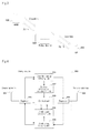
  • FIG. 7 is a schematic diagram describing an operation of the radio communication system according to working examples 1 and 2 of the present invention.
  • FIG. 8 is a schematic diagram describing an operation of a radio communication system according to working example 1 of the present invention.
  • FIG. 9 is a flow chart describing an operation of a radio communication system according to working example 2 of the present invention.
  • FIG. 10 is a schematic diagram describing an operation of the radio communication system according to working example 2 of the present invention.
  • FIG. 11 is a schematic diagram showing an outlined structure of a radio communication system according to working example 3 of the present invention.
  • FIG. 12 is a block diagram showing a structure of a relay device according to working example 3 of the present invention.
  • FIG. 13 is a flow chart describing an operation of the radio communication system according to working example 3 of the present invention.
  • FIG. 14 is a schematic diagram describing an operation of the radio communication system according to working example 3 of the present invention.
  • FIG. 1 shows an outlined structure of a radio communication system according to an embodiment of the present invention.
  • the radio communication system has base station 10 , mobile station 20 , and relay device 30 that amplifies a downlink signal and an uplink signal transmitted from base station 10 and mobile station 20 and re-transmits them.
  • FIG. 1 shows one base stations 10 , one mobile stations 20 , and one relay devices 30 , their numbers are not limited to one, but may be plural.
  • OFDMA Orthogonal Frequency Division Multiple Access
  • SC-FDMA Single-Carrier Frequency Division Multiple Access
  • FIG. 2 shows a structure of relay device 30 according to this embodiment.
  • FIG. 2 shows only constituent elements with respect to an uplink signal relaying operation that is a characteristic portion of the present invention.
  • relay device 30 has antenna for base station 31 , antenna for mobile station 32 , uplink signal relaying unit 33 , frequency information acquisition unit 34 , uplink signal detection unit 35 , and control unit 36 .
  • Uplink signal relaying unit 33 performs an uplink signal relaying operation that amplifies an uplink signal transmitted from base station 10 and received by antenna for mobile station 32 and re-transmits the amplified uplink signal to mobile station 20 through the antenna for base station 31 .
  • Frequency information acquisition unit 34 acquires frequency information that represents a frequency band that base station 10 uses for an uplink channel periodically or at particular timings.
  • frequency information may be acquired according to the following methods, details will be described later.
  • Uplink signal detection unit 35 determines whether or not the average reception power of the uplink signal in the frequency band represented by the frequency information acquired by frequency information acquisition unit 34 exceeds a predetermined threshold.
  • Control unit 36 controls the uplink signal relaying operation that uplink signal relaying unit 33 performs based on the determined result of uplink signal detection unit 35 .
  • the uplink signal relaying operation may be turned on.
  • relay device 30 acquires frequency information that represents the frequency band that mobile station 20 uses for the uplink channel periodically or at predetermined timings and controls the uplink signal relaying operation based on the uplink signal in the frequency band.
  • relay device 30 can reflect the changed frequency band to the uplink signal relaying operation, relay device 30 can perform the uplink signal relaying operation corresponding to the changed frequency band of the uplink channel.
  • FIG. 3 shows an outlined structure of a radio communication system according to working example 1 of the present invention.
  • the radio communication system has eNB (evolved Node B) 100 , UE (User Equipment) 200 , and relay device 300 .
  • eNB evolved Node B
  • UE User Equipment
  • relay device 300 relay device
  • eNB 100 is an example of base station 10 shown in FIG. 1 ;
  • UE 200 is an example of mobile station 20 shown in FIG. 1 ;
  • relay device 300 is an example of relay device 30 shown in FIG. 1 .
  • FIG. 3 shows one eNB 100 , one UE 200 , and one relay device 300 , their numbers are not specified to one, but may be plural.
  • the radio communication system according to this working example is applied to for example an FDD-LTE (Frequency Division Duplex-Long Term Evolution) scheme based mobile telephone system defined in 3GPP (Third Generation Partnership Project/[URL] http://www.3gpp.org).
  • FDD-LTE Frequency Division Duplex-Long Term Evolution
  • the transmission scheme for a downlink from eNB 100 to UE 200 is OFDMA
  • the transmission scheme for an uplink from UE 200 to eNB 100 is SC-FDMA.
  • relay device 300 is located at a position where relay device 300 can receive physical downlink channel signals such as PBCH (Physical Broadcast Channel), PDSCH (Physical Downlink Shared Channel), and PDCCH (Physical Downlink Control Channel), and physical downlink signals such as P-SS (Primary Synchronization Signal), S-SS (Secondary Synchronization Signal), and RS (Reference Signal) with a predetermined signal power level.
  • PBCH Physical Broadcast Channel
  • PDSCH Physical Downlink Shared Channel
  • PDCCH Physical Downlink Control Channel
  • P-SS Primary Synchronization Signal
  • S-SS Secondary Synchronization Signal
  • RS Reference Signal
  • eNB 100 receives signals that have been amplified and re-transmitted as physical uplink channel signals such as PRACH (Physical Random Access Channel), PUSCH (Physical Uplink Shared Channel), PUCCH (Physical Uplink Control Channel) and physical uplink signals such as RS (Reference Signal).
  • PRACH Physical Random Access Channel
  • PUSCH Physical Uplink Shared Channel
  • PUCCH Physical Uplink Control Channel
  • RS Reference Signal
  • FIG. 4 shows a structure of relay device 300 according to this working example.
  • relay device 300 has donor antenna 301 , service antenna 302 , downlink signal relaying unit 303 , uplink signal relaying unit 304 , duplexers 305 and 306 , system information acquisition unit 307 , uplink signal detection unit 308 , and control unit 309 .
  • donor antenna 301 is an example of antenna for base station 31 shown in FIG. 2 ; service antenna 302 is an example of antenna for mobile station 32 shown in FIG. 2 ; uplink signal relaying unit 304 is an example of uplink signal relaying unit 33 shown in FIG. 2 ; system information acquisition unit 307 is an example of frequency information acquisition unit 34 shown in FIG. 2 ; uplink signal detection unit 308 is an example of uplink signal detection unit 35 shown in FIG. 2 ; and control unit 309 is an example of control unit 36 shown in FIG. 2 .
  • a downlink signal transmitted from eNB 100 is received by donor antenna 301 and output to downlink signal relaying unit 303 through duplexer 305 .
  • downlink signal relaying unit 303 filters the downlink signal received by donor antenna 301 depending on whether or not the downlink signal is included in the frequency band needed for the relaying operation, causes an amplifier to amplify the filtered downlink signal, and then outputs the amplified downlink signal.
  • the downlink signal that is output from downlink signal relaying unit 303 is output to service antenna 302 through duplexer 306 and then re-transmitted through service antenna 302 to UE 200 in the neighborhood of relay device 300 .
  • the frequency band for downlink signals that downlink signal relaying unit 303 relays, the gain of the amplifier, and ON/OFF operations of the downlink signal relaying operation are set by control unit 309 .
  • an uplink signal transmitted from UE 200 is received by service antenna 302 and then output to uplink signal relaying unit 304 through duplexer 306 .
  • Uplink signal relaying unit 304 performs an uplink signal relaying operation that amplifies the uplink signal received by service antenna 302 and re-transmits the amplified uplink signal to eNB 100 through donor antenna 301 .
  • uplink signal relaying unit 304 filters the uplink signal received by service antenna 302 depending on whether or not uplink signal is included in the frequency band needed for the relaying operation, causes an amplifier to amplify the filtered uplink signal, and then outputs the amplified uplink signal.
  • the uplink signal that is output from uplink signal relaying unit 304 is output to donor antenna 301 through duplexer 305 and re-transmitted to eNB 100 through donor antenna 301 .
  • the frequency band for uplink signals that uplink signal relaying unit 304 relays, the gain of the amplifier, and the ON/OFF operations of the uplink signal relaying operation are set by control unit 309 .
  • downlink signal relaying unit 303 inputs a downlink signal to system information acquisition unit 307 .
  • system information acquisition unit 307 transforms the downlink signal into base band digital signals having I phase and Q phase according to an orthogonal demodulation technique. Thereafter, system information acquisition unit 307 performs a process for the downlink base band signals according to an FFT (Fast Fourier Transform) or IDFT (Inverse Discrete Fourier Transform) technique and, using an equalizer as an LTE based UE, performs, acquires system information from PBCH and PDSCH, and notifies control unit 309 of the acquired system information.
  • the system information contains information for PRACH that is a random access channel that UE 200 initially uses when it originates a call. This information also contains frequency information that represents a frequency band that PRACH uses (for example, prach-FrequencyOffset).
  • uplink signal relaying unit 304 inputs an uplink signal to uplink signal detection unit 308 .
  • FIG. 5 shows a structure of uplink signal detection unit 308 .
  • uplink signal detection unit 308 has orthogonal demodulation unit 308 A, FFT unit 308 B, reception power measurement unit 308 C, and level determination unit 308 D.
  • orthogonal demodulation unit 308 A located in uplink signal detection unit 308 transforms the uplink signal into base band digital signals having I and Q phases according to the orthogonal demodulation technique. Thereafter, FFT unit 308 B performs an FFT process for the base band digital signals having I and Q phases so as to transform the signals into base band digital signals corresponding to individual subcarriers.
  • Reception power measurement unit 308 C measures the average reception power of base band digital signals corresponding to the individual subcarriers.
  • level determination unit 308 D acquires frequency information for PRACH contained in the system information from control unit 309 .
  • level determination unit 308 D acquires predetermined threshold A that has been set for control unit 309 and determines whether or not the average reception power of a subcarrier corresponding to the frequency band that PRACH uses exceeds threshold A (hereinafter, this operation is referred to as the level determination operation). If the average reception power of PRACH exceeds threshold A, level determination unit 308 D notifies control unit 309 about that.
  • control unit 309 When control unit 309 is notified by uplink signal detection unit 308 that the average reception power of PRACH exceeds threshold A, control unit 309 causes uplink signal relaying unit 304 to turn on the uplink signal relaying operation.
  • level determination unit 308 D continues the level determination operation for the average reception power of PRACH.
  • the level determination operation is performed based on threshold B (B ⁇ A).
  • threshold B has been set for control unit 309 and thereby acquired therefrom.
  • level determination unit 308 D notifies control unit 309 about that.
  • control unit 309 When control unit 309 is notified by uplink signal detection unit 308 that the average reception power of PRACH becomes equal to or lower than threshold B, after a predetermined period elapses, if control unit 309 is not notified by uplink signal detection unit 308 that the average reception power of PRACH exceeds threshold B again, control unit 309 causes uplink signal relaying unit 304 to turn off the uplink signal relaying operation.
  • relay device 300 while relay device 300 is stopping the uplink signal relaying operation (at step S 1 ), relay device 300 acquires service information from a downlink signal transmitted through PBCH and PDSCH from eNB 100 (at steps S 2 and S 3 ). In addition, relay device 300 acquires frequency information that represents a frequency band that PRACH uses (at step S 4 ).
  • relay device 300 starts the level determination operation for the average reception power of the frequency band that PRACH uses (at step S 5 ).
  • relay device 300 determines whether or not the average reception power of the uplink signal in the frequency band that PRACH uses from among uplink signals received from UE 200 exceeds threshold A (at steps S 6 and S 7 ).
  • the average reception power is measured periodically in a sufficiently short period.
  • relay device 300 starts the uplink signal relaying operation (at step S 8 ; refer to the lower illustration shown in FIG. 7 ) so as to relay the signal of PRACH that has been just received and other uplink signals (at steps S 9 , S 10 , and S 11 ). If it takes a time before relay device 300 starts the uplink signal relaying operation, the signal of PRACH that UE 200 has just transmitted may not be relayed to eNB 100 . However, in this case, since UE 200 transmits the signal of PRACH again, no adverse result may occur in the system.
  • relay device 300 periodically measures the average reception power of the frequency band that PRACH uses and performs the level determination operation for that based on threshold B (B ⁇ A) (at step S 12 ).
  • relay device 300 Even if the average reception power becomes equal to or lower than threshold B (the result of level determination operation is NG) at step S 12 , before a predetermined period elapses, if the average reception power exceeds threshold B (at steps S 13 and S 14 ), relay device 300 continues the uplink signal relaying operation (at step S 15 ).
  • relay device 300 After the average reception power becomes equal to or lower than threshold B (the result of level determination operation is NG at step S 12 ; refer to the upper illustration shown in FIG. 8 ) and then a predetermined period elapses, if the average reception power does not exceed threshold B (at steps S 13 and S 14 ), relay device 300 stops the uplink signal relaying operation (at step S 16 ; refer to the lower illustration shown in FIG. 8 ). In this case, relay device 300 returns to the process at step S 7 (not shown) and then starts the level determination operation for the average reception power based on threshold A again.
  • the frequency band that PRACH uses may be changed by the communication provider during its operation.
  • relay device 300 periodically acquires system information and performs the process shown in FIG. 6 based on the acquired system information.
  • relay device 300 reflects the changed frequency band to the uplink signal relaying operation. Since the period for which relay device 300 acquires system information needs to be as short as possible in consideration of the object of the present invention where relay device 300 follows changed frequency band, it is assumed that the period is around 1 second. However, according to the present invention, since the period is not specified to 1 second, it may be 1 second or shorter.
  • relay device 300 periodically acquires frequency information that represents the frequency band of PRACH from system information transmitted from eNB 100 and controls the uplink signal relaying operation based on the uplink signal in the frequency band.
  • relay device 300 can reflect the changed frequency band to the uplink signal relaying operation, relay device 300 can perform the uplink signal relaying operation corresponding to the changed frequency band.
  • relay device 300 since relay device 300 extracts uplink signals of individual frequency bands according to the FFT technique, even if the frequency band of PRACH is changed, relay device 300 can easily follow the changed frequency band. Moreover, according to this working example, the circuit scale of relay device 300 can be reduced compared to the structure that uses a digital filter that performs the extracting process.
  • relay device 300 After relay device 300 starts the uplink signal relaying operation, relay device 300 performs the level determination operation for the average reception power in the frequency band that PRACH uses. After a predetermined period elapses, if the result of the level determination operation for PRACH is still NG, relay device 300 stops the uplink signal relaying operation.
  • relay device 300 after relay device 300 starts the uplink signal relaying operation, it also performs the level determination operation for the average reception power of a frequency band that a physical channel other than PRACH (for example, PUCCH) uses. After a predetermined period elapses, if the result of the level determination for PRACH and the result of the level determination operation for the physical uplink channel other than PRACH are NG, relay device 300 stops the uplink signal relaying operation.
  • PRACH Physical channel other than PRACH
  • threshold C may be the same value as threshold A and threshold B or different from threshold A and threshold B.
  • level determination unit 308 D located in uplink signal detection unit 308 and control unit 309 perform the following operations.
  • Level determination unit 308 D acquires not only frequency information for PRACH, threshold A, and threshold B from level determination unit 308 D, but also frequency information for the physical uplink channel other than PRACH and threshold C from control unit 309 .
  • the frequency information for the physical uplink channel other than PRACH is contained in the system information, whereas threshold C has been set for control unit 309 .
  • level determination unit 308 D notifies control unit 309 about that.
  • control unit 309 After relay device 300 starts the uplink signal relaying operation, if control unit 309 is notified by uplink signal detection unit 308 that the average reception power of PRACH becomes equal to or lower than threshold B, after a predetermined period elapses, if control unit 309 is not notified by uplink signal detection unit 308 that the average reception power of PRACH exceeds threshold B and/or that the average reception power of the physical uplink channel other than PRACH exceeds threshold C, control unit 309 notifies and causes uplink signal relaying unit 304 to turn off the uplink signal relaying operation.
  • relay device 300 performs the process from steps S 1 to S 3 so as to acquire system information like the process shown in FIG. 6 .
  • relay device 300 acquires frequency information for PRACH and PUCCH from the system information (at step S 20 ).
  • relay device 300 performs the process from step S 5 to S 12 like the process shown in FIG. 6 .
  • relay device 300 Even if the average reception power of PRACH becomes equal to or lower than threshold B (the result of level determination operation is NG at step s 12 ), before a predetermined period elapses, if the average reception power of PRACH exceeds threshold B or the average reception power of PUCCH exceeds threshold C (at steps S 13 and S 21 ), relay device 300 continues the uplink signal relaying operation (at step S 15 ).
  • relay device 300 stops the uplink signal relaying operation (at step S 16 ; refer to the lower illustration shown in FIG. 10 ).
  • step S 16 is the same as the process shown in FIG. 6 .
  • the physical uplink channel other than PRACH is not limited to the foregoing PUCCH, but limited any physical channel on which a predetermined uplink signal is periodically transmitted (for example, PUSCH).
  • relay device 300 according to this working example is different from relay device 300 according to working example 1 only in that the former performs not only the level determination operation for PRACH, but also that for the physical uplink channel other than PRACH and reflects the results to the uplink signal relaying operation.
  • the effects of the relay device 300 according to working example 2 are the same as those of relay device 300 according to working example 1.
  • FIG. 11 shows an outlined structure of a radio communication system according to working example 3 of the present invention.
  • the radio communication system according to this working example is different from relay device 300 according to each of working examples 1 and 2 only in that the former is also provided with monitor control unit 400 connected to relay device 300 .
  • Monitor control unit 400 is a computer or a server that notifies relay device 300 of setup information about the relaying operation of relay device 300 .
  • the setup information includes frequency information that represents a frequency band that UE 200 uses for an uplink channel.
  • monitor control unit 400 may notify relay device 300 of the foregoing setup information periodically or at predetermined timings, for example, whenever frequency information is updated.
  • the period during which monitor control unit 400 periodically notifies relay device 300 of the setup information may be the same as the period during which relay device 300 according to working example 1 acquires system information.
  • FIG. 12 shows a structure of relay device 300 according to this working example.
  • relay device 300 according to this working example is different from relay device 300 according to each of working examples 1 and 2 only in that the former is provided with external interface 310 that is connected to monitor control unit 400 instead of system information acquisition unit 307 .
  • external interface 310 is an example of frequency information acquisition unit 34 shown in FIG. 2 .
  • External interface 310 acquires setup information including the foregoing frequency information from monitor control unit 400 periodically or at predetermined timings as described above.
  • threshold A, threshold B, and threshold C have been set for control unit 309 .
  • threshold A, threshold B, and threshold C may be acquired from monitor control unit 400 .
  • relay device 300 After relay device 300 starts the uplink signal relaying operation, relay device 300 performs the level determination operation only for PRACH like relay device 300 according to working example 1.
  • FIG. 13 units similar to those shown in FIG. 6 are denoted by similar reference numerals.
  • relay device 300 performs the process from steps S 5 to S 12 like the process shown in FIG. 6 .
  • relay device 300 stops the uplink signal relaying operation (at step S 16 ; refer to the lower illustration shown in FIG. 14 ).
  • step S 16 is the same as the process shown in FIG. 6 .
  • relay device 300 may perform the level determination operation for PUCCH like relay device 300 according to working example 2 ( FIG. 9 ).
  • steps S 2 and S 3 shown in FIG. 9 are replaced with steps S 30 and S 31 shown in FIG. 13 and the frequency information for PRACH and PUCCH are acquired from the setup information.
  • relay device 300 according to this working example is different from relay device 300 according to each of working examples 1 and 2 only in that the former acquires frequency information from monitor control unit 400 .
  • the effects of relay device 300 according to this working example are the same as those of relay device 300 according to each of working examples 1 and 2.
  • the present invention may be applied to the following cases and environments.
  • the relay device is provided with one antenna through which an uplink signal is transmitted and one antenna through which a downlink signal is received.
  • the relay device may be provided with two or more antennas through which uplink signals are transmitted and two or more antennas through which downlink signals are received.
  • the relay device may not perform the uplink signal relaying operation.
  • the downlink signal relaying operation may be performed only if the total reception power of all downlink signals exceeds a reference power level. According to working examples 1 and 2, a condition in which the downlink signal relaying operation is performed only if system information has been correctly acquired, may be added.
  • the method by which the relay device according to the present invention performs may be applied to a program that causes a computer to execute the method.
  • the program can be stored in a storage medium and may also be provided to the outside through a network.

Abstract

A relay device according to the present invention includes an uplink signal relaying unit that performs an uplink signal relaying operation that amplifies an uplink signal transmitted through an uplink channel from a mobile station and re-transmits the amplified uplink signal to a base station; a frequency information acquisition unit that acquires frequency information that represents a frequency band that said mobile station uses for the uplink channel periodically or at predetermined timings; an uplink signal detection unit that determines whether or not the average reception power of the uplink signal in the frequency band represented by the frequency information acquired by said frequency information acquisition unit exceeds a predetermined threshold; and a control unit that controls the uplink signal relaying operation performed by said uplink signal relaying unit based on a determined result of said uplink signal detection unit.

Description

This application is the National Phase of PCT/JP2010/070440, filed Nov. 17, 2010, which claims priority to Japanese Application No. 2009-292521, filed Dec. 24, 2009, the disclosures of which are hereby incorporated by reference in their entirety.
TECHNICAL FIELD
The present invention relates to a Relay device, a relay system, a relay method, a radio communication system, and a program.
BACKGROUND ART
Recently, to improve users' convenience and satisfaction, communication providers have given high priority to the reduction of blind areas such as shadow of buildings in downtown, the insides of restaurants, cell edges, and high-rise buildings where radio waves of mobile stations such as mobile phones can not sufficiently reach.
In an area that does not have an enough space for the facility of a base station or a mountain area where the number of users is small, repeaters (relay devices) that perform a relaying operation that amplifies signals transmitted from base stations and mobile stations and re-transmits the amplified signals are often installed instead of new base stations.
However, since relay devices also amplify not only signals received from base stations and mobile stations, but also interference waves and noises received together with those signals and relay the resultant signals, the relay devices may lead to an adverse affect upon the system such that they deteriorate signals received by base stations and neighbor mobile stations.
Thus, it is desirable that while mobile stations in the neighborhood of a relay device are not communicating with a base station, the relay device needs to restrict the relaying operation whenever possible.
To do that, recent relay devices are controlled such that they perform the relaying operation only if the total reception power of all uplink signals exceeds a reference power level that has been set for them.
Radio communication systems that have been implemented or evaluated (hereinafter it is assumed that they includes mobile phone systems or the like) use a transmission scheme in which a wide system frequency band is ensured and segmented for individual mobile stations when necessary.
For example, in LTE (Long Term Evolution) that is being standardized in 3GPP (Third Generation Partnership Project), a frequency band that is as wide as a maximum of 20 MHz is segmented into 100 resource blocks and also chronologically segmented into short periods. The resource blocks are assigned to control channels and data channels.
Thus, in a high traffic area, the entire system frequency band is always used. In contrast, in a low traffic area, part of the system frequency band is used for a short period.
Consequently, under the LTE's system environment, when the relay device controls the relaying operation based on the total reception power of all uplink signals, namely the total reception power of the entire system frequency band, if the number of mobile stations in the neighborhood of the relay device is very small, even if a mobile station transmits an uplink signal, since the total reception power of the uplink signal that the relay device receives does not exceed the reference power level, the relay device may thus not correctly perform the relaying operation.
To solve such a problem, it can be contemplated that a relay device extracts an uplink signal in a frequency band that a mobile station uses for an uplink channel and performs the relaying operation based on only the reception power of the extracted uplink signal according to a narrow band signal extracting technique presented in Patent Literature 1.
RELATED ART LITERATURE Patent Literature
  • Patent Literature 1: JP2008-503907, Publication (translated version)
SUMMARY OF THE INVENTION Problem to be Solved by the Invention
However, Patent Literature 1 does not disclose any specific method that serves to extract a narrow band signal. In addition, according to the technique presented in Patent Literature 1, it is supposed that a signal in a predetermined frequency hand is extracted as a narrow band signal.
However, a frequency band that mobile stations use for uplink channels may be changed by their communication provider during its operation.
In such a situation, even if a relay device uses the technique that is presented in Patent Literature 1 and that extracts a signal of a predetermined frequency band, since the relay device cannot follow a changed frequency band for uplink channels, it cannot correctly perform the relaying operation for uplink signals.
Therefore, an object of the present invention is to solve the foregoing problem and provide a relay device, a relay system, a relay method, a radio communication system, and a program that can perform the uplink signal relaying operation corresponding to a changed frequency band that mobile stations use for uplink channels.
Means that Solve the Problem
A relay device according to the present invention comprises:
an uplink signal relaying unit that performs an uplink signal relaying operation that amplifies an uplink signal transmitted through an uplink channel from a mobile station and re-transmits the amplified uplink signal to a base station;
a frequency information acquisition unit that acquires frequency information that represents a frequency band that said mobile station uses for the uplink channel periodically or at predetermined timings;
an uplink signal detection unit that determines whether or not the average reception power of the uplink signal in the frequency band represented by the frequency information acquired by said frequency information acquisition unit exceeds a predetermined threshold; and
a control unit that controls the uplink signal relaying operation performed by said uplink signal relaying unit based on a determined result of said uplink signal detection unit.
A relay system according to the present invention comprises:
an uplink signal relaying unit that performs an uplink signal relaying operation that amplifies an uplink signal transmitted through an uplink channel from a mobile station and re-transmits the amplified uplink signal to a base station;
a frequency information acquisition unit that acquires frequency information that represents a frequency band that said mobile station uses for the uplink channel periodically or at predetermined timings;
an uplink signal detection unit that determines whether or not the average reception power of the uplink signal in the frequency band represented by the frequency information acquired by said frequency information acquisition unit exceeds a predetermined threshold; and
a control unit that controls the uplink signal relaying operation performed by said uplink signal relaying unit based on a determined result of said uplink signal detection unit.
A relay method according to the present invention comprises:
performing an uplink signal relaying operation that amplifies an uplink signal transmitted through an uplink channel from a mobile station and re-transmits the amplified uplink signal to a base station;
acquiring frequency information that represents a frequency band that said mobile station uses for the uplink channel periodically or at predetermined timings;
determining whether or not the average reception power of the uplink signal in the frequency band represented by said acquired frequency information exceeds a predetermined threshold; and
controlling said uplink signal relaying operation based on said determined result.
A radio communication system according to the present invention comprises:
a mobile station; a base station; and a relay device,
wherein said relay device, includes:
an uplink signal relaying unit that performs an uplink signal relaying operation that amplifies an uplink signal transmitted through an uplink channel from said mobile station and re-transmits the amplified uplink signal to said base station;
a frequency information acquisition unit that acquires frequency information that represents a frequency band that said mobile station uses for the uplink channel periodically or at predetermined timings;
an uplink signal detection unit that determines whether or not the average reception power of the uplink signal in the frequency band represented by the frequency information acquired by said frequency information acquisition unit exceeds a predetermined threshold; and
a control unit that controls the uplink signal relaying operation performed by said uplink signal relaying unit based on a determined result of said uplink signal detection unit.
A program according to the present invention causes a relay device to execute procedures comprising:
performing an uplink signal relaying operation that amplifies an uplink signal transmitted through an uplink channel from a mobile station and re-transmits the amplified uplink signal to a base station;
acquiring frequency information that represents a frequency band that said mobile station uses for the uplink channel periodically or at predetermined timings;
determining whether or not the average reception power of the uplink signal in the frequency band represented by said acquired frequency information exceeds a predetermined threshold; and
controlling said uplink signal relaying operation based on said determined result.
Effect of the Invention
According to the present invention, a relay device acquires frequency information that represents a frequency band that mobile stations use for uplink channels periodically or at predetermined timings and controls the relaying operation for uplink signals based on the uplink signals in the frequency band that the acquired frequency information represents.
Thus, even if a frequency band that is used for uplink channels is changed, since the relay device can reflect the changed frequency band to its relaying operation, it can control the uplink signal relaying operation corresponding to the changed frequency band.
BRIEF DESCRIPTION OF DRAWINGS
[FIG. 1] is a schematic diagram showing an outlined structure of a radio communication system according to an embodiment of the present invention.
[FIG. 2] is a block diagram showing a structure of a relay device according to the embodiment of the present invention.
[FIG. 3] is a schematic diagram showing an outlined structure of a radio communication system according to working examples 1 and 2 of the present invention.
[FIG. 4] is a block diagram showing a structure of a relay device according to working examples 1 and 2 of the present invention.
[FIG. 5] is a block diagram showing a structure of an uplink detection unit located in a relay device according to working examples 1, 2, and 3 of the present invention.
[FIG. 6] is a flow chart describing an operation of the radio communication system according to working example 1 of the present invention.
[FIG. 7] is a schematic diagram describing an operation of the radio communication system according to working examples 1 and 2 of the present invention.
[FIG. 8] is a schematic diagram describing an operation of a radio communication system according to working example 1 of the present invention.
[FIG. 9] is a flow chart describing an operation of a radio communication system according to working example 2 of the present invention.
[FIG. 10] is a schematic diagram describing an operation of the radio communication system according to working example 2 of the present invention.
[FIG. 11] is a schematic diagram showing an outlined structure of a radio communication system according to working example 3 of the present invention.
[FIG. 12] is a block diagram showing a structure of a relay device according to working example 3 of the present invention.
[FIG. 13] is a flow chart describing an operation of the radio communication system according to working example 3 of the present invention.
[FIG. 14] is a schematic diagram describing an operation of the radio communication system according to working example 3 of the present invention.
BEST MODES THAT CARRY OUT THE INVENTION
Next, with reference to the accompanying drawings, an embodiment of the present invention will be described.
FIG. 1 shows an outlined structure of a radio communication system according to an embodiment of the present invention.
Referring to FIG. 1, the radio communication system according to this embodiment has base station 10, mobile station 20, and relay device 30 that amplifies a downlink signal and an uplink signal transmitted from base station 10 and mobile station 20 and re-transmits them.
Although FIG. 1 shows one base stations 10, one mobile stations 20, and one relay devices 30, their numbers are not limited to one, but may be plural.
It is assumed that an uplink transmission scheme (OFDMA (Orthogonal Frequency Division Multiple Access), SC-FDMA (Single-Carrier Frequency Division Multiple Access), or the like) in which a wide system frequency band is segmented and assigned to mobile station 20 is used.
FIG. 2 shows a structure of relay device 30 according to this embodiment. FIG. 2 shows only constituent elements with respect to an uplink signal relaying operation that is a characteristic portion of the present invention.
Referring to FIG. 2, relay device 30 according to this embodiment has antenna for base station 31, antenna for mobile station 32, uplink signal relaying unit 33, frequency information acquisition unit 34, uplink signal detection unit 35, and control unit 36.
Uplink signal relaying unit 33 performs an uplink signal relaying operation that amplifies an uplink signal transmitted from base station 10 and received by antenna for mobile station 32 and re-transmits the amplified uplink signal to mobile station 20 through the antenna for base station 31.
Frequency information acquisition unit 34 acquires frequency information that represents a frequency band that base station 10 uses for an uplink channel periodically or at particular timings.
Although frequency information may be acquired according to the following methods, details will be described later.
    • (1) Frequency information is periodically acquired from system information transmitted from base station 10.
    • (2) Frequency information is acquired from setup information concerning which a monitor control device (not shown) notifies relay device 30 periodically or at predetermined timings.
Uplink signal detection unit 35 determines whether or not the average reception power of the uplink signal in the frequency band represented by the frequency information acquired by frequency information acquisition unit 34 exceeds a predetermined threshold.
Control unit 36 controls the uplink signal relaying operation that uplink signal relaying unit 33 performs based on the determined result of uplink signal detection unit 35. As a control method for the uplink signal relaying operation, if the average reception power exceeds the predetermined threshold, the uplink signal relaying operation may be turned on.
As described above, according to this embodiment, relay device 30 acquires frequency information that represents the frequency band that mobile station 20 uses for the uplink channel periodically or at predetermined timings and controls the uplink signal relaying operation based on the uplink signal in the frequency band.
Thus, even if the frequency band of the uplink channel is changed, since relay device 30 can reflect the changed frequency band to the uplink signal relaying operation, relay device 30 can perform the uplink signal relaying operation corresponding to the changed frequency band of the uplink channel.
WORKING EXAMPLES
Next, working examples of the embodiment of the present invention will be described.
Working Example 1
FIG. 3 shows an outlined structure of a radio communication system according to working example 1 of the present invention.
Referring to FIG. 3, the radio communication system according to this working example has eNB (evolved Node B) 100, UE (User Equipment) 200, and relay device 300.
In FIG. 3, eNB 100 is an example of base station 10 shown in FIG. 1; UE 200 is an example of mobile station 20 shown in FIG. 1; and relay device 300 is an example of relay device 30 shown in FIG. 1.
Although FIG. 3 shows one eNB 100, one UE 200, and one relay device 300, their numbers are not specified to one, but may be plural.
The radio communication system according to this working example is applied to for example an FDD-LTE (Frequency Division Duplex-Long Term Evolution) scheme based mobile telephone system defined in 3GPP (Third Generation Partnership Project/[URL] http://www.3gpp.org).
Thus, the transmission scheme for a downlink from eNB 100 to UE 200 is OFDMA, whereas the transmission scheme for an uplink from UE 200 to eNB 100 is SC-FDMA.
It is assumed that relay device 300 is located at a position where relay device 300 can receive physical downlink channel signals such as PBCH (Physical Broadcast Channel), PDSCH (Physical Downlink Shared Channel), and PDCCH (Physical Downlink Control Channel), and physical downlink signals such as P-SS (Primary Synchronization Signal), S-SS (Secondary Synchronization Signal), and RS (Reference Signal) with a predetermined signal power level.
In contrast, it is assumed that since UE 200 is not located at a position where UE 200 can directly receive such physical downlink channel signals and physical signals from eNB 100, UE 200 receives signals that have been amplified and re-transmitted by relay device 300.
Likewise, it is assumed that eNB 100 receives signals that have been amplified and re-transmitted as physical uplink channel signals such as PRACH (Physical Random Access Channel), PUSCH (Physical Uplink Shared Channel), PUCCH (Physical Uplink Control Channel) and physical uplink signals such as RS (Reference Signal).
FIG. 4 shows a structure of relay device 300 according to this working example.
Referring to FIG. 4, relay device 300 according to this working example has donor antenna 301, service antenna 302, downlink signal relaying unit 303, uplink signal relaying unit 304, duplexers 305 and 306, system information acquisition unit 307, uplink signal detection unit 308, and control unit 309.
In FIG. 4, donor antenna 301 is an example of antenna for base station 31 shown in FIG. 2; service antenna 302 is an example of antenna for mobile station 32 shown in FIG. 2; uplink signal relaying unit 304 is an example of uplink signal relaying unit 33 shown in FIG. 2; system information acquisition unit 307 is an example of frequency information acquisition unit 34 shown in FIG. 2; uplink signal detection unit 308 is an example of uplink signal detection unit 35 shown in FIG. 2; and control unit 309 is an example of control unit 36 shown in FIG. 2.
A downlink signal transmitted from eNB 100 is received by donor antenna 301 and output to downlink signal relaying unit 303 through duplexer 305.
Downlink signal relaying unit 303 performs a downlink signal relaying operation that amplifies the downlink signal received by donor antenna 301 and re-transmits the amplified downlink signal to UE 200 through service antenna 302.
Specifically, downlink signal relaying unit 303 filters the downlink signal received by donor antenna 301 depending on whether or not the downlink signal is included in the frequency band needed for the relaying operation, causes an amplifier to amplify the filtered downlink signal, and then outputs the amplified downlink signal. The downlink signal that is output from downlink signal relaying unit 303 is output to service antenna 302 through duplexer 306 and then re-transmitted through service antenna 302 to UE 200 in the neighborhood of relay device 300. At this point, the frequency band for downlink signals that downlink signal relaying unit 303 relays, the gain of the amplifier, and ON/OFF operations of the downlink signal relaying operation are set by control unit 309.
On the other hand, an uplink signal transmitted from UE 200 is received by service antenna 302 and then output to uplink signal relaying unit 304 through duplexer 306.
Uplink signal relaying unit 304 performs an uplink signal relaying operation that amplifies the uplink signal received by service antenna 302 and re-transmits the amplified uplink signal to eNB 100 through donor antenna 301.
Specifically, uplink signal relaying unit 304 filters the uplink signal received by service antenna 302 depending on whether or not uplink signal is included in the frequency band needed for the relaying operation, causes an amplifier to amplify the filtered uplink signal, and then outputs the amplified uplink signal. The uplink signal that is output from uplink signal relaying unit 304 is output to donor antenna 301 through duplexer 305 and re-transmitted to eNB 100 through donor antenna 301. At this point, the frequency band for uplink signals that uplink signal relaying unit 304 relays, the gain of the amplifier, and the ON/OFF operations of the uplink signal relaying operation are set by control unit 309.
As a characteristic operation of the present invention, downlink signal relaying unit 303 inputs a downlink signal to system information acquisition unit 307.
When the downlink signal that is input from downlink signal relaying unit 303 is an RF (Radio Frequency) signal or an IF (Inter frequency) signal, system information acquisition unit 307 transforms the downlink signal into base band digital signals having I phase and Q phase according to an orthogonal demodulation technique. Thereafter, system information acquisition unit 307 performs a process for the downlink base band signals according to an FFT (Fast Fourier Transform) or IDFT (Inverse Discrete Fourier Transform) technique and, using an equalizer as an LTE based UE, performs, acquires system information from PBCH and PDSCH, and notifies control unit 309 of the acquired system information. The system information contains information for PRACH that is a random access channel that UE 200 initially uses when it originates a call. This information also contains frequency information that represents a frequency band that PRACH uses (for example, prach-FrequencyOffset).
As a further characteristic operation of the present invention, uplink signal relaying unit 304 inputs an uplink signal to uplink signal detection unit 308.
FIG. 5 shows a structure of uplink signal detection unit 308.
Referring to FIG. 5, uplink signal detection unit 308 has orthogonal demodulation unit 308A, FFT unit 308B, reception power measurement unit 308C, and level determination unit 308D.
When an uplink signal that is input from uplink signal relaying unit 304 is an RF signal or an IF signal, orthogonal demodulation unit 308A located in uplink signal detection unit 308 transforms the uplink signal into base band digital signals having I and Q phases according to the orthogonal demodulation technique. Thereafter, FFT unit 308B performs an FFT process for the base band digital signals having I and Q phases so as to transform the signals into base band digital signals corresponding to individual subcarriers. Reception power measurement unit 308C measures the average reception power of base band digital signals corresponding to the individual subcarriers. Thereafter, level determination unit 308D acquires frequency information for PRACH contained in the system information from control unit 309. In addition, level determination unit 308D acquires predetermined threshold A that has been set for control unit 309 and determines whether or not the average reception power of a subcarrier corresponding to the frequency band that PRACH uses exceeds threshold A (hereinafter, this operation is referred to as the level determination operation). If the average reception power of PRACH exceeds threshold A, level determination unit 308D notifies control unit 309 about that.
When control unit 309 is notified by uplink signal detection unit 308 that the average reception power of PRACH exceeds threshold A, control unit 309 causes uplink signal relaying unit 304 to turn on the uplink signal relaying operation.
After the uplink signal relaying operation is turned ON, level determination unit 308D continues the level determination operation for the average reception power of PRACH. In this case, the level determination operation is performed based on threshold B (B≦A). Like threshold A, threshold B has been set for control unit 309 and thereby acquired therefrom.
If the average reception power of PRACH becomes equal to or lower than threshold B or thereafter if the average reception power of PRACH exceeds threshold B again, level determination unit 308D notifies control unit 309 about that.
When control unit 309 is notified by uplink signal detection unit 308 that the average reception power of PRACH becomes equal to or lower than threshold B, after a predetermined period elapses, if control unit 309 is not notified by uplink signal detection unit 308 that the average reception power of PRACH exceeds threshold B again, control unit 309 causes uplink signal relaying unit 304 to turn off the uplink signal relaying operation.
Next, with reference to FIG. 6, FIG. 7, and FIG. 8, the operation of the radio communication system according to this working example will be described.
Referring to FIG. 6,while relay device 300 is stopping the uplink signal relaying operation (at step S1), relay device 300 acquires service information from a downlink signal transmitted through PBCH and PDSCH from eNB 100 (at steps S2 and S3). In addition, relay device 300 acquires frequency information that represents a frequency band that PRACH uses (at step S4).
Thereafter, relay device 300 starts the level determination operation for the average reception power of the frequency band that PRACH uses (at step S5).
First, relay device 300 determines whether or not the average reception power of the uplink signal in the frequency band that PRACH uses from among uplink signals received from UE 200 exceeds threshold A (at steps S6 and S7). The average reception power is measured periodically in a sufficiently short period.
If the average reception power exceeds threshold A at step S7 (the result of level determination operation is OK; refer to the lower illustration shown in FIG. 7), relay device 300 starts the uplink signal relaying operation (at step S8; refer to the lower illustration shown in FIG. 7) so as to relay the signal of PRACH that has been just received and other uplink signals (at steps S9, S10, and S11). If it takes a time before relay device 300 starts the uplink signal relaying operation, the signal of PRACH that UE 200 has just transmitted may not be relayed to eNB 100. However, in this case, since UE 200 transmits the signal of PRACH again, no adverse result may occur in the system.
Thereafter, relay device 300 periodically measures the average reception power of the frequency band that PRACH uses and performs the level determination operation for that based on threshold B (B≦A) (at step S12).
Even if the average reception power becomes equal to or lower than threshold B (the result of level determination operation is NG) at step S12, before a predetermined period elapses, if the average reception power exceeds threshold B (at steps S13 and S14), relay device 300 continues the uplink signal relaying operation (at step S15).
After the average reception power becomes equal to or lower than threshold B (the result of level determination operation is NG at step S12; refer to the upper illustration shown in FIG. 8) and then a predetermined period elapses, if the average reception power does not exceed threshold B (at steps S13 and S14), relay device 300 stops the uplink signal relaying operation (at step S16; refer to the lower illustration shown in FIG. 8). In this case, relay device 300 returns to the process at step S7 (not shown) and then starts the level determination operation for the average reception power based on threshold A again.
The frequency band that PRACH uses may be changed by the communication provider during its operation. Thus, relay device 300 periodically acquires system information and performs the process shown in FIG. 6 based on the acquired system information. As a result, even if the frequency band that PRACH uses is changed, relay device 300 reflects the changed frequency band to the uplink signal relaying operation. Since the period for which relay device 300 acquires system information needs to be as short as possible in consideration of the object of the present invention where relay device 300 follows changed frequency band, it is assumed that the period is around 1 second. However, according to the present invention, since the period is not specified to 1 second, it may be 1 second or shorter.
As described above, according to this working example, relay device 300 periodically acquires frequency information that represents the frequency band of PRACH from system information transmitted from eNB 100 and controls the uplink signal relaying operation based on the uplink signal in the frequency band.
Thus, even if the frequency band of PRACH is changed, since relay device 300 can reflect the changed frequency band to the uplink signal relaying operation, relay device 300 can perform the uplink signal relaying operation corresponding to the changed frequency band.
In addition, according to this working example, since relay device 300 extracts uplink signals of individual frequency bands according to the FFT technique, even if the frequency band of PRACH is changed, relay device 300 can easily follow the changed frequency band. Moreover, according to this working example, the circuit scale of relay device 300 can be reduced compared to the structure that uses a digital filter that performs the extracting process.
Working Example 2
Although the structure of the radio communication system according to working example 2 is the same as the structure of the radio communication system according to working example 1, they differ in their operations.
According to working example 1, after relay device 300 starts the uplink signal relaying operation, relay device 300 performs the level determination operation for the average reception power in the frequency band that PRACH uses. After a predetermined period elapses, if the result of the level determination operation for PRACH is still NG, relay device 300 stops the uplink signal relaying operation.
In contrast, according to this working example, after relay device 300 starts the uplink signal relaying operation, it also performs the level determination operation for the average reception power of a frequency band that a physical channel other than PRACH (for example, PUCCH) uses. After a predetermined period elapses, if the result of the level determination for PRACH and the result of the level determination operation for the physical uplink channel other than PRACH are NG, relay device 300 stops the uplink signal relaying operation.
However, according to this working example, the level determination operation for the physical uplink channel other than PRACH is performed based on threshold C. According to this working example, threshold C may be the same value as threshold A and threshold B or different from threshold A and threshold B.
To accomplish the foregoing operation, level determination unit 308D located in uplink signal detection unit 308 and control unit 309 perform the following operations.
Level determination unit 308D acquires not only frequency information for PRACH, threshold A, and threshold B from level determination unit 308D, but also frequency information for the physical uplink channel other than PRACH and threshold C from control unit 309. The frequency information for the physical uplink channel other than PRACH is contained in the system information, whereas threshold C has been set for control unit 309.
After relay device 300 starts the uplink signal relaying operation, if the average reception power of PRACH becomes equal to or lower than threshold B or thereafter if the average reception power of PRACH exceeds threshold B again or the average reception power of the physical uplink channel other than PRACH exceeds threshold C, level determination unit 308D notifies control unit 309 about that.
After relay device 300 starts the uplink signal relaying operation, if control unit 309 is notified by uplink signal detection unit 308 that the average reception power of PRACH becomes equal to or lower than threshold B, after a predetermined period elapses, if control unit 309 is not notified by uplink signal detection unit 308 that the average reception power of PRACH exceeds threshold B and/or that the average reception power of the physical uplink channel other than PRACH exceeds threshold C, control unit 309 notifies and causes uplink signal relaying unit 304 to turn off the uplink signal relaying operation.
Next, with reference to FIG. 9 and FIG. 10, the operation of the radio communication system according to this working example will be described. In the following, it is assumed that the physical uplink channel other than PRACH is PUCCH. In FIG. 9, units similar to those shown in FIG. 6 are denoted by similar reference numerals.
Referring to FIG. 9, relay device 300 performs the process from steps S1 to S3 so as to acquire system information like the process shown in FIG. 6.
Thereafter, relay device 300 acquires frequency information for PRACH and PUCCH from the system information (at step S20).
Thereafter, relay device 300 performs the process from step S5 to S12 like the process shown in FIG. 6.
Even if the average reception power of PRACH becomes equal to or lower than threshold B (the result of level determination operation is NG at step s12), before a predetermined period elapses, if the average reception power of PRACH exceeds threshold B or the average reception power of PUCCH exceeds threshold C (at steps S13 and S21), relay device 300 continues the uplink signal relaying operation (at step S15).
In contrast, after the average reception power of PEACH becomes equal to or lower than threshold B (the result of level determination operation is NG at step S12) and then a predetermined period elapses, if the average reception power of PRACH does not exceed threshold B and the average reception power of PUCCH does not exceed threshold C (at steps S13 and S21; refer to the upper illustration shown in FIG. 10), relay device 300 stops the uplink signal relaying operation (at step S16; refer to the lower illustration shown in FIG. 10).
The process after step S16 is the same as the process shown in FIG. 6.
According to this working example, the physical uplink channel other than PRACH is not limited to the foregoing PUCCH, but limited any physical channel on which a predetermined uplink signal is periodically transmitted (for example, PUSCH).
As described above, relay device 300 according to this working example is different from relay device 300 according to working example 1 only in that the former performs not only the level determination operation for PRACH, but also that for the physical uplink channel other than PRACH and reflects the results to the uplink signal relaying operation. Thus, the effects of the relay device 300 according to working example 2 are the same as those of relay device 300 according to working example 1.
Working Example 3
FIG. 11 shows an outlined structure of a radio communication system according to working example 3 of the present invention.
Referring to FIG. 11, the radio communication system according to this working example is different from relay device 300 according to each of working examples 1 and 2 only in that the former is also provided with monitor control unit 400 connected to relay device 300.
Monitor control unit 400 is a computer or a server that notifies relay device 300 of setup information about the relaying operation of relay device 300. The setup information includes frequency information that represents a frequency band that UE 200 uses for an uplink channel. At this point, monitor control unit 400 may notify relay device 300 of the foregoing setup information periodically or at predetermined timings, for example, whenever frequency information is updated. The period during which monitor control unit 400 periodically notifies relay device 300 of the setup information may be the same as the period during which relay device 300 according to working example 1 acquires system information.
FIG. 12 shows a structure of relay device 300 according to this working example.
Referring to FIG. 12, relay device 300 according to this working example is different from relay device 300 according to each of working examples 1 and 2 only in that the former is provided with external interface 310 that is connected to monitor control unit 400 instead of system information acquisition unit 307.
In other words, according to this working example, external interface 310 is an example of frequency information acquisition unit 34 shown in FIG. 2. External interface 310 acquires setup information including the foregoing frequency information from monitor control unit 400 periodically or at predetermined timings as described above.
According to working examples 1 and 2, it was assumed that threshold A, threshold B, and threshold C have been set for control unit 309. In contrast, according to working example 3, threshold A, threshold B, and threshold C may be acquired from monitor control unit 400.
Next, with reference to FIG. 13 and FIG. 14, the operation of the radio communication system according to this working example will be described. In the following, it is assumed that after relay device 300 starts the uplink signal relaying operation, relay device 300 performs the level determination operation only for PRACH like relay device 300 according to working example 1. In FIG. 13, units similar to those shown in FIG. 6 are denoted by similar reference numerals.
Referring to FIG. 13, while relay device 300 is stopping the uplink signal relaying operation (at step S1), relay device 300 acquires setup information from monitor control unit 400 (at steps S30 and S31) and also frequency information that represents the frequency band that PRACH uses from the setup information (at step S32).
Thereafter, relay device 300 performs the process from steps S5 to S12 like the process shown in FIG. 6.
Even if the average reception power of PRACH becomes equal to or lower than threshold B (the result of level determination operation is NG at step S12), before a predetermined period elapses, if the average reception power of PRACH exceeds threshold B (at steps S13 and S 14), relay device 300 continues the uplink signal relaying operation (at step S15).
In contrast, after the average reception power of PRACH becomes equal to or lower than threshold B (the result of level determination operation is NG at step S12), after a predetermined period elapses, if the average reception power of PRACH does not exceed threshold B (at steps S13 and S14; refer to the upper illustration shown in FIG. 14), relay device 300 stops the uplink signal relaying operation (at step S16; refer to the lower illustration shown in FIG. 14).
The process after step S16 is the same as the process shown in FIG. 6.
According to this working example, after relay device 300 starts the uplink signal relaying operation, relay device 300 may perform the level determination operation for PUCCH like relay device 300 according to working example 2 (FIG. 9). In this case, steps S2 and S3 shown in FIG. 9 are replaced with steps S30 and S31 shown in FIG. 13 and the frequency information for PRACH and PUCCH are acquired from the setup information.
As described above, relay device 300 according to this working example is different from relay device 300 according to each of working examples 1 and 2 only in that the former acquires frequency information from monitor control unit 400. Thus, the effects of relay device 300 according to this working example are the same as those of relay device 300 according to each of working examples 1 and 2.
With reference to the embodiment and working examples, the present invention has been described. However, it should be understood by those skilled in the art that the structure and details of the present invention may be changed in various manners without departing from the scope of the present invention.
For example, the present invention may be applied to the following cases and environments.
    • (1) According to working examples 1 to 3, FDD-LTE scheme based mobile phone systems are exemplified. Alternatively, the present invention may be applied to OFDMA or SC-FDMA scheme based mobile phone networks and radio networks.
    • (2) According to the embodiment and working examples 1 to 3, a relay device and a base station are radio-linked. Alternatively, a relay device and a base station may be linked with a cable (a coaxial cable, an optical cable, a LAN cable, or the like).
However, when a relay device and a base station are linked with a cable, the effects of the present invention can be fulfilled when the following conditions are satisfied:
when a plurality of relay devices are linked to a base station and uplink signals transmitted from the plurality of relay devices are combined by the base station.
when a cable extending from a relay device is connected to a cable that connects a base station and its antenna.
    • (3) According to the embodiment and working examples 1 to 3, a relay device is provided with one antenna through which a downlink signal is transmitted and one antenna through which an uplink signal is received. Alternatively, the relay device may be provided with two or more antennas through which downlink signals are transmitted and two or more antennas through which uplink signals are received.
Likewise, according to the embodiment and working examples 1 to 3, the relay device is provided with one antenna through which an uplink signal is transmitted and one antenna through which a downlink signal is received. Alternatively, the relay device may be provided with two or more antennas through which uplink signals are transmitted and two or more antennas through which downlink signals are received.
    • (4) According to the embodiment and working examples 1 to 3, one relay device is provided. Alternatively, the functions of the relay device may be distributed to a plurality of units (hardware units) and they may be configured as “relay system” that radio- or cable-links these units.
    • (5) According to working examples 1 to 3, a down link signal and an uplink signal relayed by the relay device are digital signals. Alternatively, these signals may be analog signals instead of digital signals.
    • (6) According to the embodiment and working examples 1 to 3, a relay device controls the uplink signal relaying operation according to the present invention independent from the downlink signal relaying operation. Alternatively, while the relay device is performing the downlink signal relaying operation, it may control the uplink signal relaying operation according to the present invention.
For example, while the relay device is not performing the downlink signal relaying operation, even if the average reception power exceeds a predetermined threshold, the relay device may not perform the uplink signal relaying operation.
Although the downlink signal relaying operation is not specifically controlled, the downlink signal relaying operation may be performed only if the total reception power of all downlink signals exceeds a reference power level. According to working examples 1 and 2, a condition in which the downlink signal relaying operation is performed only if system information has been correctly acquired, may be added.
    • (7) According to working examples 1 to 3, after a relay device starts the uplink signal relaying operation, if the result of the level determination operation denotes that the average reception power does not exceed a predetermined threshold for a predetermined period, the relay device stops the uplink signal relaying operation. Alternatively, the relay device may decrease the gain of an amplifier that amplifies the uplink signal (lower than the gain of the amplifier acquired when the relay device starts the uplink signal relaying operation) and that continues the uplink signal operation with very low power instead of stopping the downlink signal relaying operation.
    • (8) According to working examples 1 to 3, when reception power measurement unit 308C measures the average reception power of a base band digital signal of a subcarrier corresponding to the frequency band of PRACH, reception power measurement unit 308C may compute a correlation of the based band digital signal and a known code sequence of PRACH and treat the computed correlation value as the average reception power of the base band digital signal of the corresponding subcarrier. Reception power measurement unit 308C may measure the average reception power for a physical uplink channel other than PRACH in the similar manner.
The method by which the relay device according to the present invention performs may be applied to a program that causes a computer to execute the method. The program can be stored in a storage medium and may also be provided to the outside through a network.

Claims (15)

The invention claimed is:
1. A relay device, comprising:
an uplink signal relaying unit that performs an uplink signal relaying operation that amplifies an uplink signal transmitted through an uplink channel from a mobile station and re-transmits the amplified uplink signal to a base station;
a frequency information acquisition unit that acquires frequency information that represents a frequency band that said mobile station uses for the uplink channel periodically or at predetermined timings;
an uplink signal detection unit that determines whether or not the average reception power of the uplink signal in the frequency band represented by the frequency information acquired by said frequency information acquisition unit exceeds a predetermined threshold;
a control unit that controls the uplink signal relaying operation performed by said uplink signal relaying unit based on a determined result of said uplink signal detection unit; and
a downlink signal relaying unit that performs a downlink signal relaying operation that amplifies the downlink signal transmitted through a downlink channel from said base station and re-transmits the amplified downlink signal to said mobile station,
wherein said frequency information acquisition unit periodically acquires system information containing said frequency information from the downlink signal received from said base station,
wherein said frequency information acquisition unit acquires frequency information that represents a first frequency band that said mobile station used for a first channel,
wherein said uplink signal detection unit determines whether or not the average reception power of the uplink signal in said first frequency band exceeds a first threshold, and
wherein said control unit causes said uplink signal relaying unit to start the uplink signal relaying operation if the average reception power of the uplink signal in said first frequency band exceeds said first threshold.
2. The relay device as set forth in claim 1,
wherein said uplink signal detection unit determines whether or not the average reception power of the uplink signal in said first frequency band exceeds a second threshold that is equal to or lower than said first threshold after said uplink signal relaying unit starts the uplink signal relaying operation, and
wherein said control unit causes said uplink signal relaying unit to stop the uplink signal relaying operation after said uplink signal relaying unit starts the uplink signal relaying operation and then a predetermined period elapses, if the average reception power of the uplink signal of said first frequency band is equal to or lower than said second threshold.
3. The relay device as set forth in claim 1,
wherein said uplink signal detection unit determines whether or not the average reception power of the uplink signal in said first frequency band exceeds a second threshold that is equal to or lower than said first threshold after said uplink signal relaying unit starts the uplink signal relaying operation, and
wherein said control unit causes said uplink signal relaying unit to decrease an amplification gain for the uplink signal and continue the uplink signal relaying operation after said uplink signal relaying unit starts the uplink signal relaying operation and then a predetermined period elapses, if the average reception power of the uplink signal of said first frequency band is equal to or lower than said second threshold.
4. The relay device as set forth in claim 1,
wherein said frequency information acquisition unit further acquires frequency information that represents a second frequency band that said mobile station uses for a second uplink channel,
wherein said uplink signal detection unit determines whether or not the average reception power of the uplink signal in said first frequency band exceeds a second threshold that is equal to or lower than said first threshold and whether or not the average reception power of the uplink signal in said second frequency band exceeds a third threshold after said uplink signal relaying unit starts the uplink signal relaying operation, and
wherein said control unit causes said uplink signal relaying unit to stop the uplink signal relaying operation after said uplink signal relaying unit starts the uplink signal relaying operation and then a predetermined period elapses, if the average reception power of the uplink signal in said first frequency band is equal to or lower than said second threshold and the average reception power of the uplink signal in said second frequency band is equal to or lower than said third threshold.
5. The relay device as set forth in claim 1,
wherein said frequency information acquisition unit further acquires frequency information that represents a second frequency band that said mobile station uses for a second uplink channel,
wherein said uplink signal detection unit determines whether or not the average reception power of the uplink signal in said first frequency band exceeds a second threshold that is equal to or lower than said first threshold and also determines whether or not the average reception power of the uplink signal in said second frequency band exceeds a third threshold after said uplink signal relaying unit starts the uplink signal relaying operation, and
wherein said control unit causes said uplink signal relaying unit to decrease an amplification gain for the uplink signal and continue the uplink signal relaying operation after said uplink signal relaying unit starts the uplink signal relaying operation and then a predetermined period elapses, if the average reception power of the uplink signal in said first frequency band is equal to or lower than said second threshold and the average reception power of the uplink signal in said second frequency band is equal to or lower than said third threshold.
6. The relay device as set forth in claim 2,
wherein said first uplink channel is a random access channel that said mobile station initially uses when it originates a call.
7. The relay device as set forth in claim 4,
wherein said first uplink channel is a random access channel that said mobile station initially uses when it originates a call, and
wherein said second uplink channel is a physical channel through which said mobile station periodically transmits a predetermined uplink signal.
8. The relay device as set forth in claim 1,
wherein said control unit causes said uplink signal relaying unit to start the uplink signal relaying operation while said downlink signal relaying unit is performing the downlink signal relaying operation and only if the average reception power of the uplink signal in said first frequency band exceeds said first threshold.
9. The relay device as set forth in claim 1,
wherein said uplink signal detection unit includes:
an orthogonal demodulation unit that transforms the uplink signal received from said mobile station by said uplink signal relaying unit into base band digital signals having I and Q phases according to an orthogonal demodulation technique;
an FFT unit that transforms the base band signals having I and Q phases according to an FFT technique so as to transform them into base band digital signals corresponding to subcarriers; and
a reception power measurement unit that measures the average reception power of the base band digital signals corresponding to the subcarriers; and
a level determination unit that determines whether or not the average reception power of an uplink signal of a subcarrier corresponding to a frequency band represented by said frequency information exceeds a predetermined threshold.
10. The relay device as set forth in claim 9,
wherein said reception power measurement unit measures the average reception power of a base band signal corresponding to a subcarrier corresponding to a frequency band used for an uplink channel in such a manner that said reception power measurement unit computes a correlation of the base band digital signal corresponding to the subcarrier and a known code sequence of the uplink channel and treats the computed correlation value as the average reception power of the base band digital signals corresponding to the subcarrier.
11. A relay system, comprising:
an uplink signal relaying unit that performs an uplink signal relaying operation that amplifies an uplink signal transmitted through an uplink channel from a mobile station and re-transmits the amplified uplink signal to a base station;
a frequency information acquisition unit that acquires frequency information that represents a frequency band that said mobile station uses for the uplink channel periodically or at predetermined timings;
an uplink signal detection unit that determines whether or not the average reception power of the uplink signal in the frequency band represented by the frequency information acquired by said frequency information acquisition unit exceeds a predetermined threshold;
a control unit that controls the uplink signal relaying operation performed by said uplink signal relaying unit based on a determined result of said uplink signal detection unit; and
a downlink signal relaying unit that performs a downlink signal relaying operation that amplifies the downlink signal transmitted through a downlink channel from said base station and re-transmits the amplified downlink signal to said mobile station,
wherein said frequency information acquisition unit periodically acquires system information containing said frequency information from the downlink signal received from said base station,
wherein said frequency information acquisition unit acquires frequency information that represents a first frequency band that said mobile station used for a first channel,
wherein said uplink signal detection unit determines whether or not the average reception power of the uplink signal in said first frequency band exceeds a first threshold, and
wherein said control unit causes said uplink signal relaying unit to start the uplink signal relaying operation if the average reception power of the uplink signal in said first frequency band exceeds said first threshold.
12. A relay method, comprising:
performing an uplink signal relaying operation that amplifies an uplink signal transmitted through an uplink channel from a mobile station and re-transmits the amplified uplink signal to a base station;
acquiring frequency information that represents a frequency band that said mobile station uses for the uplink channel periodically or at predetermined timings;
determining whether or not the average reception power of the uplink signal in the frequency band represented by said acquired frequency information exceeds a predetermined threshold;
controlling said uplink signal relaying operation based on said determined result; and
performing a downlink signal relaying operation that amplifies the downlink signal transmitted through a downlink channel from said base station and re-transmits the amplified downlink signal to said mobile station,
wherein said step of acquiring frequency information comprises periodically acquiring system information containing said frequency information from the downlink signal received from said base station,
wherein said step of acquiring frequency information comprises acquiring frequency information that represents a first frequency band that said mobile station used for a first channel,
wherein said step of determining comprises determining whether or not the average reception power of the uplink signal in said first frequency band exceeds a first threshold, and
wherein said step of controlling said uplink signal relaying operation comprises causing to start the step of performing an uplink signal relaying operation if the average reception power of the uplink signal in said first frequency band exceeds said first threshold.
13. A relay device, comprising:
an uplink signal relaying unit that performs an uplink signal relaying operation that amplifies an uplink signal transmitted through an uplink channel from a mobile station and re-transmits the amplified uplink signal to a base station;
a frequency information acquisition unit that acquires frequency information that represents a frequency band that said mobile station uses for the uplink channel periodically or at predetermined timings;
an uplink signal detection unit that determines whether or not the average reception power of the uplink signal in the frequency band represented by the frequency information acquired by said frequency information acquisition unit exceeds a predetermined threshold; and
a control unit that controls the uplink signal relaying operation performed by said uplink signal relaying unit based on a determined result of said uplink signal detection unit,
wherein said frequency information acquisition unit acquires frequency information that represents a first frequency band that said mobile station used for a first channel,
wherein said uplink signal detection unit determines whether or not the average reception power of the uplink signal in said first frequency band exceeds a first threshold,
wherein said control unit causes said uplink signal relaying unit to start the uplink signal relaying operation if the average reception power of the uplink signal in said first frequency band exceeds said first threshold,
wherein said frequency information acquisition unit is connected to a monitor control unit located outside said relay device and acquires control information containing said frequency information, said control information being transmitted from said monitor control unit periodically or at predetermined timings.
14. A relay system, comprising:
an uplink signal relaying unit that performs an uplink signal relaying operation that amplifies an uplink signal transmitted through an uplink channel from a mobile station and re-transmits the amplified uplink signal to a base station;
a frequency information acquisition unit that acquires frequency information that represents a frequency band that said mobile station uses for the uplink channel periodically or at predetermined timings;
an uplink signal detection unit that determines whether or not the average reception power of the uplink signal in the frequency band represented by the frequency information acquired by said frequency information acquisition unit exceeds a predetermined threshold; and
a control unit that controls the uplink signal relaying operation performed by said uplink signal relaying unit based on a determined result of said uplink signal detection unit,
wherein said frequency information acquisition unit acquires frequency information that represents a first frequency band that said mobile station used for a first channel,
wherein said uplink signal detection unit determines whether or not the average reception power of the uplink signal in said first frequency band exceeds a first threshold,
wherein said control unit causes said uplink signal relaying unit to start the uplink signal relaying operation if the average reception power of the uplink signal in said first frequency band exceeds said first threshold,
wherein said frequency information acquisition unit is connected to a monitor control unit located outside said relay device and acquires control information containing said frequency information, said control information being transmitted from said monitor control unit periodically or at predetermined timings.
15. A relay method, comprising:
performing an uplink signal relaying operation that amplifies an uplink signal transmitted through an uplink channel from a mobile station and re-transmits the amplified uplink signal to a base station;
acquiring frequency information that represents a frequency band that said mobile station uses for the uplink channel periodically or at predetermined timings;
determining whether or not the average reception power of the uplink signal in the frequency band represented by said acquired frequency information exceeds a predetermined threshold; and
controlling said uplink signal relaying operation based on said determined result,
wherein said step of acquiring frequency information comprises acquiring frequency information that represents a first frequency band that said mobile station used for a first channel,
wherein said step of determining comprises determining whether or not the average reception power of the uplink signal in said first frequency band exceeds a first threshold,
wherein said step of controlling said uplink signal relaying operation comprises causing to start the step of performing an uplink signal relaying operation if the average reception power of the uplink signal in said first frequency band exceeds said first threshold, and
wherein said step of acquiring frequency information comprises connecting to a monitor control unit and acquiring control information containing said frequency information, said control information being transmitted from said monitor control unit periodically or at predetermined timings.
US13/518,275 2009-12-24 2010-11-17 Relay device, relay system, relay method, radio communication system, and program Expired - Fee Related US8755328B2 (en)

Applications Claiming Priority (3)

Application Number Priority Date Filing Date Title
JP2009292521 2009-12-24
JP2009-292521 2009-12-24
PCT/JP2010/070440 WO2011077862A1 (en) 2009-12-24 2010-11-17 Relay apparatus, relay system, relay method, wireless communication system, and program

Publications (2)

Publication Number Publication Date
US20120257532A1 US20120257532A1 (en) 2012-10-11
US8755328B2 true US8755328B2 (en) 2014-06-17

Family

ID=44195404

Family Applications (1)

Application Number Title Priority Date Filing Date
US13/518,275 Expired - Fee Related US8755328B2 (en) 2009-12-24 2010-11-17 Relay device, relay system, relay method, radio communication system, and program

Country Status (5)

Country Link
US (1) US8755328B2 (en)
JP (1) JP5712934B2 (en)
KR (1) KR101402569B1 (en)
CN (1) CN102687550B (en)
WO (1) WO2011077862A1 (en)

Families Citing this family (17)

* Cited by examiner, † Cited by third party
Publication number Priority date Publication date Assignee Title
WO2013044957A1 (en) * 2011-09-28 2013-04-04 Fujitsu Limited Activation of supplementary transmission unit
CN103916864B (en) * 2013-01-04 2017-09-29 中国移动通信集团公司 A kind of wireless discharging-directly station and its transmission signal method
WO2015171808A1 (en) * 2014-05-06 2015-11-12 Nextivity, Inc. Detecting uplink repeater capacity
JP6193481B2 (en) * 2014-05-09 2017-09-06 株式会社Nttドコモ User device and transmission control method
CN106211026B (en) * 2014-12-22 2019-05-24 中兴通讯股份有限公司 A kind of method, network control node and user equipment for realizing the selection of equipment straightforward trunking
WO2017026542A1 (en) * 2015-08-13 2017-02-16 株式会社Nttドコモ Relay device and relay method
JP6645849B2 (en) * 2016-01-29 2020-02-14 株式会社東芝 Communication relay device, communication relay system, method and program
JP6691448B2 (en) * 2016-07-08 2020-04-28 電気興業株式会社 Distributed antenna device
JP2018011137A (en) * 2016-07-11 2018-01-18 株式会社東芝 Communication relay device, communication relay system, method, and program
WO2018187778A1 (en) * 2017-04-07 2018-10-11 Commscope Technologies Llc Output muting for active repeater systems
CN109152016B (en) 2017-06-16 2022-04-05 华为技术有限公司 Communication method and device
FR3092457B1 (en) * 2019-02-01 2021-01-22 Sigfox Method and system for wireless communication between transmitting devices and a receiving device by means of a simultaneous repeater device
FR3092456B1 (en) * 2019-02-01 2021-01-15 Sigfox Method and system for wireless communication between a sending device and a receiving device by means of a repeater device, without loss of information on a physical property
CN114616865A (en) * 2019-11-08 2022-06-10 华为技术有限公司 Communication method and device
JP7366947B2 (en) 2021-01-07 2023-10-23 アンリツ株式会社 Measuring device and measuring method
CN115473615A (en) * 2021-06-11 2022-12-13 北京三星通信技术研究有限公司 Method and apparatus for receiving and transmitting data and/or control information
CN113891366B (en) * 2021-10-15 2024-02-06 中国联合网络通信集团有限公司 Relay device control method, device, system and storage medium

Citations (10)

* Cited by examiner, † Cited by third party
Publication number Priority date Publication date Assignee Title
JPH1070498A (en) 1996-08-27 1998-03-10 Kokusai Electric Co Ltd Frequency conversion repeater
JP2002111571A (en) 2000-09-28 2002-04-12 Nippon Telegr & Teleph Corp <Ntt> Radio repeater
JP2006503481A (en) 2002-10-15 2006-01-26 ワイデファイ インコーポレイテッド Wireless local area network repeater with automatic gain control to extend network coverage
US7233771B2 (en) 2004-05-13 2007-06-19 Widefi, Inc. Non-frequency translating repeater with downlink detection for uplink and downlink synchronization
JP2007251789A (en) 2006-03-17 2007-09-27 Ntt Docomo Inc Wireless repeating apparatus and method
JP2008236370A (en) 2007-03-20 2008-10-02 Fujitsu Ltd Radio transmission system
US20090047898A1 (en) * 2005-03-29 2009-02-19 Matsushita Electric Industrial Co., Ltd. Communication system, communication relay apparatus, and communication relay method
JP2009524303A (en) 2006-01-17 2009-06-25 上海原動力通信科技有限公司 Method, apparatus and terminal for physical layer random access in a broadband TDD mobile communication system
JP2009246508A (en) 2008-03-28 2009-10-22 Fujitsu Ltd Relay station for wireless communication, wireless communication system, and method of controlling relay station
US7944871B2 (en) * 2005-04-28 2011-05-17 Panasonic Corporation Communication relay apparatus and communication relay method

Family Cites Families (2)

* Cited by examiner, † Cited by third party
Publication number Priority date Publication date Assignee Title
JP2000324548A (en) * 1999-05-12 2000-11-24 Nec Corp Mobile communication system and mobile communication channel switching method
CN101119153B (en) * 2006-08-03 2010-12-08 中兴通讯股份有限公司 Method for selecting wireless digital relay system and transmission time spacing

Patent Citations (14)

* Cited by examiner, † Cited by third party
Publication number Priority date Publication date Assignee Title
JPH1070498A (en) 1996-08-27 1998-03-10 Kokusai Electric Co Ltd Frequency conversion repeater
JP2002111571A (en) 2000-09-28 2002-04-12 Nippon Telegr & Teleph Corp <Ntt> Radio repeater
US8060009B2 (en) 2002-10-15 2011-11-15 Qualcomm Incorporated Wireless local area network repeater with automatic gain control for extending network coverage
JP2006503481A (en) 2002-10-15 2006-01-26 ワイデファイ インコーポレイテッド Wireless local area network repeater with automatic gain control to extend network coverage
US7233771B2 (en) 2004-05-13 2007-06-19 Widefi, Inc. Non-frequency translating repeater with downlink detection for uplink and downlink synchronization
JP2008503907A (en) 2004-05-13 2008-02-07 ワイデファイ インコーポレイテッド Non-frequency conversion repeater for detection and media access control
US8023885B2 (en) 2004-05-13 2011-09-20 Qualcomm Incorporated Non-frequency translating repeater with downlink detection for uplink and downlink synchronization
US20090047898A1 (en) * 2005-03-29 2009-02-19 Matsushita Electric Industrial Co., Ltd. Communication system, communication relay apparatus, and communication relay method
US7944871B2 (en) * 2005-04-28 2011-05-17 Panasonic Corporation Communication relay apparatus and communication relay method
JP2009524303A (en) 2006-01-17 2009-06-25 上海原動力通信科技有限公司 Method, apparatus and terminal for physical layer random access in a broadband TDD mobile communication system
US8072932B2 (en) 2006-01-17 2011-12-06 Shanghai Ultimate Power Communications Technology Co., Ltd. Method, device, and terminal for physical layer random access in wideband TDD mobile communication system
JP2007251789A (en) 2006-03-17 2007-09-27 Ntt Docomo Inc Wireless repeating apparatus and method
JP2008236370A (en) 2007-03-20 2008-10-02 Fujitsu Ltd Radio transmission system
JP2009246508A (en) 2008-03-28 2009-10-22 Fujitsu Ltd Relay station for wireless communication, wireless communication system, and method of controlling relay station

Also Published As

Publication number Publication date
KR20120112645A (en) 2012-10-11
WO2011077862A1 (en) 2011-06-30
CN102687550B (en) 2016-08-03
CN102687550A (en) 2012-09-19
JPWO2011077862A1 (en) 2013-05-02
JP5712934B2 (en) 2015-05-07
US20120257532A1 (en) 2012-10-11
KR101402569B1 (en) 2014-05-30

Similar Documents

Publication Publication Date Title
US8755328B2 (en) Relay device, relay system, relay method, radio communication system, and program
US9253647B2 (en) Mobile device for a smart relay network
US11742931B2 (en) Time division duplex (TDD) network protection repeater
CN105814936B (en) The method and its communication equipment of auxiliary component carrier measurement are deactivated
US9287965B2 (en) Smart relay network
US8873463B2 (en) Method and apparatus for transmitting/receiving data in a relay communication system
US8767865B2 (en) Wireless station, an interference estimation method, a wireless communication system and a computer program
EP2605421A1 (en) Method, system and wireless communication device for auxiliary transmission to adjacent channels
US9820222B2 (en) Wireless communication method, wireless communication system, base station, and wireless terminal
US10341159B2 (en) Head-end device and method of recovering synchronization detection error using the same
JP4887413B2 (en) Non-regenerative wireless relay device and wireless relay system
US9198230B2 (en) Radio base station and communication control method
KR102372870B1 (en) Relay device obtaining synchronization based on aritifical intelligence and operating method of the relay device
KR101712914B1 (en) Method and apparatus of relaying operation using uplink resource
KR101825417B1 (en) Interference cancellation repeater
JP2012114861A (en) Base station and communication control method
KR20200090449A (en) Relay system for improving accuracy of synchronization and synchronization method in the system
KR102541290B1 (en) Relay device and operating method of the relay device
EP3573255B1 (en) Repeater and operating method of the repeater
US20230136719A1 (en) Excessive interference indication
US11101970B2 (en) Repeater and operating method thereof
US20240056126A1 (en) Relay station, transmission method for relay station, and communication system
US20230050960A1 (en) Target cell selection of autonomous mobile repeaters
KR101486855B1 (en) Method and apparatus for controlling output level of mobile telecommunication signal
CN112118060A (en) Method, apparatus, and computer readable medium for channel sensing

Legal Events

Date Code Title Description
AS Assignment

Owner name: NEC CORPORATION, JAPAN

Free format text: ASSIGNMENT OF ASSIGNORS INTEREST;ASSIGNOR:NAKADA, SUGURU;REEL/FRAME:028425/0364

Effective date: 20120601

AS Assignment

Owner name: NEC CORPORATION, JAPAN

Free format text: CORRECTIVE ASSIGNMENT TO CORRECT THE APPLICATION NUMBER 12518275 PREVIOUSLY RECORDED ON REEL 028425 FRAME 0364. ASSIGNOR(S) HEREBY CONFIRMS THE ASSIGNMENT;ASSIGNOR:NAKADA, SURURU;REEL/FRAME:028467/0319

Effective date: 20120601

STCF Information on status: patent grant

Free format text: PATENTED CASE

MAFP Maintenance fee payment

Free format text: PAYMENT OF MAINTENANCE FEE, 4TH YEAR, LARGE ENTITY (ORIGINAL EVENT CODE: M1551)

Year of fee payment: 4

FEPP Fee payment procedure

Free format text: MAINTENANCE FEE REMINDER MAILED (ORIGINAL EVENT CODE: REM.); ENTITY STATUS OF PATENT OWNER: LARGE ENTITY

LAPS Lapse for failure to pay maintenance fees

Free format text: PATENT EXPIRED FOR FAILURE TO PAY MAINTENANCE FEES (ORIGINAL EVENT CODE: EXP.); ENTITY STATUS OF PATENT OWNER: LARGE ENTITY

STCH Information on status: patent discontinuation

Free format text: PATENT EXPIRED DUE TO NONPAYMENT OF MAINTENANCE FEES UNDER 37 CFR 1.362

FP Lapsed due to failure to pay maintenance fee

Effective date: 20220617