US8837101B2 - Voltage-modifying device for electric meter - Google Patents
Voltage-modifying device for electric meter Download PDFInfo
- Publication number
- US8837101B2 US8837101B2 US13/210,499 US201113210499A US8837101B2 US 8837101 B2 US8837101 B2 US 8837101B2 US 201113210499 A US201113210499 A US 201113210499A US 8837101 B2 US8837101 B2 US 8837101B2
- Authority
- US
- United States
- Prior art keywords
- voltage
- electric meter
- power supply
- modifying device
- predetermined power
- Prior art date
- Legal status (The legal status is an assumption and is not a legal conclusion. Google has not performed a legal analysis and makes no representation as to the accuracy of the status listed.)
- Active, expires
Links
Images


Classifications
-
- G—PHYSICS
- G01—MEASURING; TESTING
- G01R—MEASURING ELECTRIC VARIABLES; MEASURING MAGNETIC VARIABLES
- G01R21/00—Arrangements for measuring electric power or power factor
- G01R21/133—Arrangements for measuring electric power or power factor by using digital technique
-
- G—PHYSICS
- G01—MEASURING; TESTING
- G01R—MEASURING ELECTRIC VARIABLES; MEASURING MAGNETIC VARIABLES
- G01R15/00—Details of measuring arrangements of the types provided for in groups G01R17/00 - G01R29/00, G01R33/00 - G01R33/26 or G01R35/00
- G01R15/08—Circuits for altering the measuring range
-
- G—PHYSICS
- G01—MEASURING; TESTING
- G01R—MEASURING ELECTRIC VARIABLES; MEASURING MAGNETIC VARIABLES
- G01R22/00—Arrangements for measuring time integral of electric power or current, e.g. electricity meters
- G01R22/06—Arrangements for measuring time integral of electric power or current, e.g. electricity meters by electronic methods
Definitions
- the subject matter disclosed herein relates generally to a voltage-modifying device. More specifically, the present disclosure relates to a voltage-modifying device for an electric meter that provides higher voltage capability, lower voltage capability and/or high voltage transient protection.
- electricity distribution is the final stage in the delivery of electricity to customers.
- a typical electrical distribution system e.g., electrical sub-stations, power lines, pole-mounted transformers, distribution wiring, electric energy meters, etc.
- the electrical distribution system carries the electricity generated from a transmission system (e.g., power plant, transformers, high voltage transmission lines, etc.) and supplies the electricity to customers via an electric meter.
- a transmission system e.g., power plant, transformers, high voltage transmission lines, etc.
- industrial application power supplies range from 120 volts (V) to 480 V. Approximately ninety-seven percent of these applications fall within the 120V to 277V range. Therefore, only approximately three percent of the industrial applications require 480 V Delta configurations. Additionally, systems for oil and irrigation applications require 480 V with substantial transients due to long transmission lines and motor starts or stops. In Canada, industrial application power supplies require 600 V. There are also a small percentage of applications that require 57V to 120V. It is cost prohibitive to qualify a new meter for each specific power supply requirement at these lower volumes. Further, it may require extensive development time to qualify these new meters.
- aspects of the invention provide for qualifying a new meter with specific power supply requirements.
- aspects of the invention include a system, including: an electric meter having a housing; and a voltage-modifying device connected to the electric meter for modifying a received voltage, such that the electric meter operates in accordance with a predetermined power supply requirement, wherein the voltage-modifying device is located within the electric meter housing or external to the electric meter housing.
- a first aspect of the invention provides a system, comprising: an electric meter having a housing; and a voltage-modifying device connected to the electric meter for modifying a received voltage, such that the electric meter operates in accordance with a predetermined power supply requirement, wherein the voltage-modifying device is located within the electric meter housing or external to the electric meter housing.
- a second aspect of the invention provides a system, comprising: a power supply; an electric meter including an electronic board within a housing; and a voltage-modifying device connected to the electronic board and the power supply, the voltage-modifying device for modifying a received voltage from the power supply, such that the electric meter operates in accordance with a predetermined power supply requirement, wherein the voltage-modifying device is located within the electric meter housing or external to the electric meter housing.
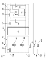
- FIG. 1 shows a schematic diagram of a system according to aspects of the invention
- FIG. 2 shows a more detailed schematic diagram of a voltage-modifying device of a system according to aspects of the invention
- FIG. 3 shows a more detailed schematic diagram of a voltage-modifying device of a system according to aspects of the invention
- FIG. 4 shows a more detailed schematic diagram of a voltage-modifying device of a system according to aspects of the invention
- FIG. 5 shows a more detailed schematic diagram of a voltage-modifying device of a system according to aspects of the invention
- FIG. 6 shows a more detailed schematic diagram of a voltage-modifying device of a system according to aspects of the invention.
- FIG. 7 shows a more detailed schematic diagram of a voltage-modifying device of a system according to aspects of the invention.
- aspects of the invention provide for qualifying a new meter with specific power supply requirements.
- aspects of the invention include a system, including: an electric meter having a housing; and a voltage-modifying device connected to the electric meter for modifying a received voltage, such that the electric meter operates in accordance with a predetermined power supply requirement, wherein the voltage-modifying device is located within the electric meter housing or external to the electric meter housing.
- power supplies for industrial applications range from 120V to 480V.
- 120V to 277V Only approximately ninety-seven percent of these applications require 120V to 277V. It is more cost effective to design a 120V to 277V power supply instead of a 120V to 480V power supply
- the voltage-modifying device enables a 120V to 277V power supply to be used for applications from 120V to 480V. Further, in oil and irrigation applications that require 480V Delta systems, overvoltage can often occur, which results in voltage transient problems.
- the voltage-modifying device described herein provides protection against high voltage transients. Therefore, it is not required to fully re-qualify a new meter for a specific power supply requirement of each application.
- a power supply 10 may be connected to a voltage-modifying device 20 .
- Voltage-modifying device 20 may be connected to an electronic board 32 of an electric meter 30 .
- the electric meter 30 includes a housing 31 .
- the voltage-modifying device 20 enables the electric meter 30 to operate in accordance with a predetermined power supply requirement.
- the voltage-modifying device 20 may be located within the housing of the electric meter 30 or external to the electric meter 30 .
- System 100 will be described with respect to a three-phase power supply system. Accordingly, three lines (i.e., phases) connect the power supply 10 to the voltage-modifying device 20 .
- An optional neutral line 107 is shown, that includes a resistor 108 .
- An additional line (an adapter terminal) 101 connects the voltage-modifying device 20 to the electric meter 30 . As will be described herein, the adapter terminal 101 provides voltage feedback and supply separation for the meter 30 .
- system 100 is applied to a three-phase power supply system, it is understood that the applications of system 100 may be applied to any now known or later developed power supply system.
- FIG. 2 a more detailed schematic diagram of the voltage-modifying device 20 of system 100 is shown.
- System 100 and voltage-modifying device 20 , is show including a first phase 102 , a second phase 104 , and a third phase 106 .
- An adapter terminal 101 connects the voltage-modifying device 20 to the electric meter 30 ( FIG. 1 ). As will be described herein, the adapter terminal 101 provides voltage feedback and supply separation for the meter 30 .
- voltage-modifying device 20 includes a surge protection circuit 40 connected to first phase 102 and second phase 104 .
- Surge protection circuit 40 includes a surge resistor 42 coupled in series with at least one varistor 44 .
- FIG. 2 shows surge protection circuit 40 including two varistors 44 ; however, it is understood that surge protection circuit 40 may include any number of varistors 44 .
- Varistor 44 may include a metal oxide varistor, or any now known or later developed type of varistor. Varistor 44 is used to protect against excess transient voltages by shunting the current created by the high voltage away from other parts of the circuit.
- Voltage-modifying device 20 includes an electromagnetic interference (EMI) filtering device 60 coupled in series with the surge protection circuit 40 .
- EMI is a disturbance that can affect the operation of the electrical circuitry within the voltage-modifying device 20 by interrupting, obstructing, or limiting the effect performance of the circuit.
- Examples of EMI filtering devices include a common mode choke, an x-capacitor, or an inductor and capacitor (“LC”) filter.
- LC inductor and capacitor
- other EMI filtering devices as known in the art, may be used.
- voltage-modifying device 20 includes an overvoltage protection module 70 .
- Overvoltage protection module 70 is configured to turn off power to the electric meter 30 ( FIG. 1 ) in response to receiving a voltage that exceeds the predetermined power supply requirement. For example, a 120 V-480 V meter may turn off the power supply voltage to the switch power mode in order to protect it when there is a voltage more than 480V.
- An overvoltage detection circuit 72 within the overvoltage protection module 70 , detects when an overvoltage occurs. In response to an overvoltage occurring, the overvoltage detection circuit 72 turns on the overvoltage protection module 70 .
- the overvoltage protection module 70 includes a diode 71 electrically connected in series with a varistor 73 , a diode 74 , and a metal-oxide-semiconductor field-effect transistor (MOSFET) 75 , which are electrically connected in parallel.
- the overvoltage protection module 70 also includes a capacitor 76 .
- overvoltage protection module may include any devices necessary to turn off power to the electric meter ( FIG. 1 ), in response to an overvoltage that exceeds the predetermined power supply requirement.
- At least one additional resistor 77 may be provided for voltage feedback.
- an additional resistor 77 is shown in FIG. 2 to provide voltage feedback of the first phase 102 to the meter 30 ( FIG. 1 ) through the adapter terminal 101 .
- This additional resistor 77 also provides a separate terminal 101 off of the first phase 102 in order to provide supply separation.
- a second additional resistor 78 may also be provided for voltage feedback and supply separation for the third phase 106 .
- the second phase 104 passes through EMI filtering device 60 and is used as a reference potential. This is often the case for a half-wave rectification system.
- FIG. 3 a detailed schematic diagram of an alternative embodiment of the voltage-modifying device 20 in FIG. 2 is shown.
- a third additional resistor 79 is provided for the second phase 104 .
- this third additional resistor 79 provides voltage feedback and supply separation for the second phase 104 .
- the second phase 104 passes through the EMI filtering device 60 .
- the voltage-modifying device 20 includes a high voltage module 80 (or step-down circuit) coupled in series with the EMI filtering device 60 .
- High voltage module 80 is configured to decrease a received voltage in response to the receiving a voltage that exceeds the predetermined power supply requirement.
- the meter may be a 120 V-277 V meter and the voltage-modifying device 20 is configured to so that meter is compatible with higher voltage lines, such as, 600 V lines.
- a buck control circuit 82 within the high voltage module 80 , regulates and reduces the voltage to a voltage level that is compatible with the meter 30 . For example, for a 120V-277V meter that is connected to 600V lines, the buck control circuit 82 , within the voltage-modifying device 20 , will reduce the voltage to a voltage that is compatible with the 120V-277V meter.
- the buck converter includes two switches (a diode 81 and a switch 83 ), an inductor 84 , and a capacitor 85 . The two switches 81 , 83 alternate between charging the inductor 84 and discharging the inductor 84 to decrease the voltage. It is understood that other configurations of a buck converter, as known in the art, may be used in high voltage module 80 .
- the high voltage module 80 may include other electrical circuit components, such as an additional diode 86 and an additional capacitor 87 . These may be known as half-wave rectification elements. However, it is understood that the high voltage module 80 may include any devices necessary to decrease the voltage to the electric meter ( FIG. 1 ), in response to a voltage that exceeds the predetermined power supply requirement.
- At least one additional resistor 77 may be provided for voltage feedback.
- an additional resistor 77 is shown in FIG. 4 to provide voltage feedback of the first phase 102 to the meter 30 ( FIG. 1 ) through the adapter terminal 101 .
- the additional resistor 77 also increases the voltage divider ratio of the voltage feedback.
- This additional resistor 77 also provides a separate terminal 101 off of the first phase 102 in order to provide supply separation.
- a second additional resistor 78 may also be provided for voltage feedback and supply separation for the third phase 106 . In this embodiment, the second phase 104 does not pass through the EMI filtering device 60 .
- FIG. 5 a detailed schematic diagram of an alternative embodiment of the voltage-modifying device 20 in FIG. 4 is shown.
- a third additional resistor 79 is provided for the second phase 104 .
- this third additional resistor 79 provides voltage feedback and supply separation for the second phase 104 .
- the second phase 104 passes through the EMI filtering device 60 .
- the voltage-modifying device 20 includes a low voltage module 90 (or a step-up circuit), such as a boost converter, coupled in series with the EMI filtering device 60 .
- Low voltage module 90 is configured to increase a received voltage in response to the receiving a voltage that does not meet the predetermined power supply requirement. For example, substation units may require 57 V-120 V power supplies, which would make the substation units not compatible with a 120V-277V meter.
- a control circuit 92 within the low voltage module 90 , regulates an input supply voltage from the power supply 10 ( FIG. 1 ) to deliver a voltage that is compatible with a predetermined power supply requirement of the meter 30 ( FIG. 1 ).
- the components within the low voltage module 90 make up a boost converter that increases the voltage from the power supply 10 ( FIG. 1 ) to the predetermined power supply requirement of the meter 30 ( FIG. 1 ).
- the boost converter includes two switches (a switch 93 and a diode 94 ), an inductor 95 , and a capacitor 96 .
- the two switches 93 , 94 alternate between charging the inductor 95 and discharging the inductor 95 to increase the voltage. It is understood that other configurations of a boost converter, as known in the art, may be used in low voltage module 90 .
- the low voltage module 90 may include other electrical circuit components, such as an additional diode 97 and an additional capacitor 98 . These may be known as half-wave rectification elements. However, it is understood that the low voltage module 90 may include any devices necessary to increase the voltage to the electric meter ( FIG. 1 ), in response to a voltage that does not meet the predetermined power supply requirement.
- At least one additional resistor 77 may be provided for voltage feedback.
- an additional resistor 77 is shown in FIG. 6 to provide voltage feedback of the first phase 102 to the meter 30 ( FIG. 1 ) through the adapter terminal 101 .
- the additional resistor 77 also increases the voltage divider ratio of the voltage feedback.
- This additional resistor 77 also provides a separate terminal 101 off of the first phase 102 in order to provide supply separation.
- a second additional resistor 78 may also be provided for voltage feedback and supply separation for the third phase 106 . In this embodiment, the second phase 104 does not pass through the EMI filtering device 60 .
- FIG. 7 a detailed schematic diagram of an alternative embodiment of the voltage-modifying device 20 in FIG. 6 is shown.
- a third additional resistor 79 is provided for the second phase 104 .
- this third additional resistor 79 provides voltage feedback and supply separation for the second phase 104 .
- the second phase 104 passes through the EMI filtering device 60 .
- the voltage-modifying device 20 may include a combination of the embodiment shown in FIGS. 4-5 and the embodiment shown in FIGS. 6-7 . That is, the voltage-modifying device 20 may include a buck-boost converter or a sepic converter, which can increase or decrease the received voltage to the predetermined power supply requirement of the meter 30 .
Abstract
Description
Claims (18)
Priority Applications (7)
| Application Number | Priority Date | Filing Date | Title |
|---|---|---|---|
| US13/210,499 US8837101B2 (en) | 2011-08-16 | 2011-08-16 | Voltage-modifying device for electric meter |
| BR102012018928-3A BR102012018928B1 (en) | 2011-08-16 | 2012-07-30 | system comprising a voltage modification device |
| JP2012173524A JP6317539B2 (en) | 2011-08-16 | 2012-08-06 | Voltage change device for electric meters |
| AU2012211433A AU2012211433B2 (en) | 2011-08-16 | 2012-08-08 | Voltage-modifying device for electric meter |
| NZ601721A NZ601721B (en) | 2011-08-16 | 2012-08-08 | Voltage-modifying device for electric meter |
| CA2785367A CA2785367C (en) | 2011-08-16 | 2012-08-09 | Voltage-modifying device for electric meter |
| EP12180017A EP2560012A1 (en) | 2011-08-16 | 2012-08-10 | Voltage-modifying device for electric meter |
Applications Claiming Priority (1)
| Application Number | Priority Date | Filing Date | Title |
|---|---|---|---|
| US13/210,499 US8837101B2 (en) | 2011-08-16 | 2011-08-16 | Voltage-modifying device for electric meter |
Publications (2)
| Publication Number | Publication Date |
|---|---|
| US20130044400A1 US20130044400A1 (en) | 2013-02-21 |
| US8837101B2 true US8837101B2 (en) | 2014-09-16 |
Family
ID=47115205
Family Applications (1)
| Application Number | Title | Priority Date | Filing Date |
|---|---|---|---|
| US13/210,499 Active 2032-09-08 US8837101B2 (en) | 2011-08-16 | 2011-08-16 | Voltage-modifying device for electric meter |
Country Status (6)
| Country | Link |
|---|---|
| US (1) | US8837101B2 (en) |
| EP (1) | EP2560012A1 (en) |
| JP (1) | JP6317539B2 (en) |
| AU (1) | AU2012211433B2 (en) |
| BR (1) | BR102012018928B1 (en) |
| CA (1) | CA2785367C (en) |
Cited By (1)
| Publication number | Priority date | Publication date | Assignee | Title |
|---|---|---|---|---|
| WO2020174004A1 (en) * | 2019-02-27 | 2020-09-03 | Phoenix Contact Gmbh & Co.Kg | Adapter for an energy meter and energy measurement device |
Families Citing this family (4)
| Publication number | Priority date | Publication date | Assignee | Title |
|---|---|---|---|---|
| WO2015015365A1 (en) * | 2013-07-31 | 2015-02-05 | Manohar Alfred | An electricity theft deterrent system and a method thereof |
| CA2832237A1 (en) | 2013-11-07 | 2015-05-07 | Circuitmeter Inc. | Isolation interface for an electricity meter and electricity metering system |
| CN106066412A (en) * | 2016-07-20 | 2016-11-02 | 柳州六品科技有限公司 | A kind of metering separate intelligent electric energy meter |
| CN107623455B (en) * | 2017-09-27 | 2023-08-22 | 深圳市富优镁科技有限公司 | Power supply system of intelligent ammeter |
Citations (15)
| Publication number | Priority date | Publication date | Assignee | Title |
|---|---|---|---|---|
| FR2438846A1 (en) | 1978-10-12 | 1980-05-09 | Riken Denshi Co Ltd | VALUE RANGE SWITCH FOR ELECTRICAL MEASURING DEVICE |
| US5392188A (en) | 1991-02-15 | 1995-02-21 | Epstein; Barry M. | Power surge transient voltage protection and filtering circuit having current controlling characteristics |
| US5544089A (en) | 1992-02-21 | 1996-08-06 | Abb Power T&D Company Inc. | Programmable electrical energy meter using multiplexed analog-to-digital converters |
| US5572396A (en) * | 1995-04-21 | 1996-11-05 | Ekstrom Industries, Inc. | Electric service safety disconnect apparatus with overvoltage and overcurrent protection |
| US5574362A (en) | 1993-06-11 | 1996-11-12 | Schneider Electric Sa | Electrical energy measuring and metering device |
| US6046582A (en) | 1998-07-30 | 2000-04-04 | United Dominion Industries, Inc. | Self-powered digital clamp meter |
| US20040027101A1 (en) * | 2002-08-08 | 2004-02-12 | Patrizio Vinciarelli | Buck-boost DC-DC switching power conversion |
| US20040032267A1 (en) * | 2002-08-14 | 2004-02-19 | The Regents Of The University Of California | DC attenuation meter |
| US20040105206A1 (en) * | 1992-02-21 | 2004-06-03 | Schleifer Fred F. | Apparatus for metering at least one type of electrical power over a predetermined range of service voltages |
| US20080234957A1 (en) | 2005-01-27 | 2008-09-25 | Electro Industries/Gauge Tech. | Intelligent Electronic Device and Method Thereof |
| US7432720B1 (en) | 2006-08-04 | 2008-10-07 | Cisco Technology, Inc. | Method and system for isolated current and voltage monitoring |
| WO2010100392A1 (en) | 2009-03-06 | 2010-09-10 | Utility Metering Services Limited | Utility meter and method of operation |
| CN201751848U (en) | 2010-06-07 | 2011-02-23 | 江苏爱可信电气有限公司 | Meter with adjustable sampling range |
| CN102116794A (en) | 2010-12-06 | 2011-07-06 | 广东雅达电子股份有限公司 | Metering method of single-phase electric energy meter with wide range |
| US20110309811A1 (en) * | 2010-06-21 | 2011-12-22 | Fujitsu Limited | Regulator apparatus |
Family Cites Families (4)
| Publication number | Priority date | Publication date | Assignee | Title |
|---|---|---|---|---|
| IL116111A0 (en) * | 1995-11-23 | 1997-11-20 | Magnify Electronic Systems 199 | Uninterruptible power system card |
| JP2005114479A (en) * | 2003-10-06 | 2005-04-28 | Cimx Kk | Measuring circuit of electric information |
| JP2008072826A (en) * | 2006-09-13 | 2008-03-27 | Fujitsu Ltd | Decentralized power circuit |
| CN102026448A (en) * | 2010-11-01 | 2011-04-20 | 王子能 | LED power circuit |
-
2011
- 2011-08-16 US US13/210,499 patent/US8837101B2/en active Active
-
2012
- 2012-07-30 BR BR102012018928-3A patent/BR102012018928B1/en active IP Right Grant
- 2012-08-06 JP JP2012173524A patent/JP6317539B2/en active Active
- 2012-08-08 AU AU2012211433A patent/AU2012211433B2/en not_active Ceased
- 2012-08-09 CA CA2785367A patent/CA2785367C/en active Active
- 2012-08-10 EP EP12180017A patent/EP2560012A1/en active Pending
Patent Citations (17)
| Publication number | Priority date | Publication date | Assignee | Title |
|---|---|---|---|---|
| US4433287A (en) | 1978-10-12 | 1984-02-21 | Riken Denshi Co., Ltd. | Range switching device for electric meter |
| FR2438846A1 (en) | 1978-10-12 | 1980-05-09 | Riken Denshi Co Ltd | VALUE RANGE SWITCH FOR ELECTRICAL MEASURING DEVICE |
| US5392188A (en) | 1991-02-15 | 1995-02-21 | Epstein; Barry M. | Power surge transient voltage protection and filtering circuit having current controlling characteristics |
| US20040105206A1 (en) * | 1992-02-21 | 2004-06-03 | Schleifer Fred F. | Apparatus for metering at least one type of electrical power over a predetermined range of service voltages |
| US5544089A (en) | 1992-02-21 | 1996-08-06 | Abb Power T&D Company Inc. | Programmable electrical energy meter using multiplexed analog-to-digital converters |
| US5574362A (en) | 1993-06-11 | 1996-11-12 | Schneider Electric Sa | Electrical energy measuring and metering device |
| US5572396A (en) * | 1995-04-21 | 1996-11-05 | Ekstrom Industries, Inc. | Electric service safety disconnect apparatus with overvoltage and overcurrent protection |
| US6046582A (en) | 1998-07-30 | 2000-04-04 | United Dominion Industries, Inc. | Self-powered digital clamp meter |
| US20040027101A1 (en) * | 2002-08-08 | 2004-02-12 | Patrizio Vinciarelli | Buck-boost DC-DC switching power conversion |
| US20040032267A1 (en) * | 2002-08-14 | 2004-02-19 | The Regents Of The University Of California | DC attenuation meter |
| US20080234957A1 (en) | 2005-01-27 | 2008-09-25 | Electro Industries/Gauge Tech. | Intelligent Electronic Device and Method Thereof |
| US7432720B1 (en) | 2006-08-04 | 2008-10-07 | Cisco Technology, Inc. | Method and system for isolated current and voltage monitoring |
| WO2010100392A1 (en) | 2009-03-06 | 2010-09-10 | Utility Metering Services Limited | Utility meter and method of operation |
| US20120026007A1 (en) * | 2009-03-06 | 2012-02-02 | Utility Metering Services Limited | Utility Meter and Method of Operation |
| CN201751848U (en) | 2010-06-07 | 2011-02-23 | 江苏爱可信电气有限公司 | Meter with adjustable sampling range |
| US20110309811A1 (en) * | 2010-06-21 | 2011-12-22 | Fujitsu Limited | Regulator apparatus |
| CN102116794A (en) | 2010-12-06 | 2011-07-06 | 广东雅达电子股份有限公司 | Metering method of single-phase electric energy meter with wide range |
Non-Patent Citations (2)
| Title |
|---|
| Search Report and Written Opinion for corresponding EP Application No. 12180017.1-1524, dated Jan. 22. 2013. |
| Unofficial English translation of Office Action from NZ dated Aug. 14, 2013. |
Cited By (1)
| Publication number | Priority date | Publication date | Assignee | Title |
|---|---|---|---|---|
| WO2020174004A1 (en) * | 2019-02-27 | 2020-09-03 | Phoenix Contact Gmbh & Co.Kg | Adapter for an energy meter and energy measurement device |
Also Published As
| Publication number | Publication date |
|---|---|
| BR102012018928B1 (en) | 2020-12-22 |
| BR102012018928A8 (en) | 2017-02-21 |
| AU2012211433B2 (en) | 2016-12-01 |
| US20130044400A1 (en) | 2013-02-21 |
| CA2785367C (en) | 2017-12-05 |
| NZ601721A (en) | 2014-02-28 |
| BR102012018928A2 (en) | 2014-03-18 |
| AU2012211433A1 (en) | 2013-03-07 |
| JP6317539B2 (en) | 2018-04-25 |
| JP2013042649A (en) | 2013-02-28 |
| EP2560012A1 (en) | 2013-02-20 |
| CA2785367A1 (en) | 2013-02-16 |
Similar Documents
| Publication | Publication Date | Title |
|---|---|---|
| CN101960550B (en) | Insulator integrated power supply | |
| US9735725B2 (en) | Methods and systems for transient voltage protection | |
| AU2012211433B2 (en) | Voltage-modifying device for electric meter | |
| US8520355B2 (en) | Methods and systems for transient voltage protection | |
| CN111697847B (en) | Weissach rectifier assembly | |
| CN105531896A (en) | System and method of providing isolated power to gate driving circuits in solid state fault current limiters | |
| CN105703322B (en) | electrical device with power quality event protection and related method | |
| WO2016048187A1 (en) | Surge protector | |
| WO2008039293A2 (en) | Power supply and electronic ballast with auxiliary protection circuit | |
| US11381076B2 (en) | AC controlled relay drive circuit | |
| CN102270858A (en) | Charging device | |
| EP3394971A1 (en) | Grounding scheme for power conversion system | |
| US11811304B2 (en) | Power converters, power systems, and methods for protecting power converters | |
| DE202015106305U1 (en) | Protection circuit for operating devices | |
| NZ601721B (en) | Voltage-modifying device for electric meter | |
| CN102064683B (en) | Wide voltage input and invariable voltage output power supply module | |
| US9654022B2 (en) | Power conversion device and control method thereof | |
| CA2954404C (en) | Voltage booster for utility meter | |
| JP2012095446A (en) | Power supply unit and withstand voltage test method therefor | |
| CN110100364B (en) | Protection of inductive components | |
| EP3543714B1 (en) | Power supply device and an associated method thereof | |
| CN106160431B (en) | Power supply change-over device and its control method | |
| KR20180131272A (en) | Data concentration unit that implements multi-step surge and noise protection | |
| US10666088B2 (en) | Inductive element protection in a power supply system | |
| EP3262901B1 (en) | Operating device for an illuminant |
Legal Events
| Date | Code | Title | Description |
|---|---|---|---|
| AS | Assignment |
Owner name: GENERAL ELECTRIC COMPANY, NEW YORK Free format text: ASSIGNMENT OF ASSIGNORS INTEREST;ASSIGNOR:ROUAUD, DIDIER GILBERT;REEL/FRAME:026863/0225 Effective date: 20110816 |
|
| STCF | Information on status: patent grant |
Free format text: PATENTED CASE |
|
| AS | Assignment |
Owner name: PNC BANK, NATIONAL ASSOCIATION, PENNSYLVANIA Free format text: SECURITY INTEREST;ASSIGNOR:MRH METERS LLC;REEL/FRAME:037359/0375 Effective date: 20151221 Owner name: CERBERUS BUSINESS FINANCE, LLC, AS AGENT, NEW YORK Free format text: PATENT SECURITY AGREEMENT;ASSIGNOR:MRH METERS LLC;REEL/FRAME:037362/0603 Effective date: 20151221 |
|
| AS | Assignment |
Owner name: MRH METERS LLC (F/K/A LJF METERS LLC), FLORIDA Free format text: ASSIGNMENT OF ASSIGNORS INTEREST;ASSIGNOR:GENERAL ELECTRIC COMPANY;REEL/FRAME:037398/0877 Effective date: 20151221 |
|
| AS | Assignment |
Owner name: ACLARA METERS LLC, FLORIDA Free format text: CHANGE OF NAME;ASSIGNOR:MRH METERS LLC;REEL/FRAME:037852/0418 Effective date: 20160115 |
|
| AS | Assignment |
Owner name: MORGAN STANLEY SENIOR FUNDING, INC., AS COLLATERAL Free format text: SECURITY AGREEMENT;ASSIGNORS:ACLARA TECHNOLOGIES LLC;ACLARA METERS LLC;REEL/FRAME:039872/0227 Effective date: 20160829 Owner name: ACLARA METERS LLC F/K/A MRH METERS LLC, MISSOURI Free format text: RELEASE OF SECURITY INTEREST IN PATENTS;ASSIGNOR:CERBERUS BUSINESS FINANCE, LLC;REEL/FRAME:039880/0908 Effective date: 20160829 Owner name: ACLARA TECHNOLOGIES LLC, MISSOURI Free format text: RELEASE OF SECURITY INTEREST IN PATENTS;ASSIGNOR:CERBERUS BUSINESS FINANCE, LLC;REEL/FRAME:039880/0908 Effective date: 20160829 |
|
| AS | Assignment |
Owner name: ACLARA METERS LLC, MISSOURI Free format text: RELEASE BY SECURED PARTY;ASSIGNOR:MORGAN STANLEY SENIOR FUNDING, INC.;REEL/FRAME:045245/0231 Effective date: 20180202 Owner name: ACLARA TECHNOLOGIES LLC, MISSOURI Free format text: RELEASE BY SECURED PARTY;ASSIGNOR:MORGAN STANLEY SENIOR FUNDING, INC.;REEL/FRAME:045245/0231 Effective date: 20180202 |
|
| MAFP | Maintenance fee payment |
Free format text: PAYMENT OF MAINTENANCE FEE, 4TH YEAR, LARGE ENTITY (ORIGINAL EVENT CODE: M1551) Year of fee payment: 4 |
|
| AS | Assignment |
Owner name: MRH METERS LLC, MISSOURI Free format text: TERMINATION AND RELEASE OF PATENT SECURITY AGREEMENT;ASSIGNOR:PNC BANK, NATIONAL ASSOCIATION;REEL/FRAME:046117/0792 Effective date: 20180202 |
|
| MAFP | Maintenance fee payment |
Free format text: PAYMENT OF MAINTENANCE FEE, 8TH YEAR, LARGE ENTITY (ORIGINAL EVENT CODE: M1552); ENTITY STATUS OF PATENT OWNER: LARGE ENTITY Year of fee payment: 8 |