US8942222B2 - Frequency synchronization in wireless communication systems - Google Patents
Frequency synchronization in wireless communication systems Download PDFInfo
- Publication number
- US8942222B2 US8942222B2 US11/668,311 US66831107A US8942222B2 US 8942222 B2 US8942222 B2 US 8942222B2 US 66831107 A US66831107 A US 66831107A US 8942222 B2 US8942222 B2 US 8942222B2
- Authority
- US
- United States
- Prior art keywords
- frequency
- signal
- base station
- modification
- mobile unit
- Prior art date
- Legal status (The legal status is an assumption and is not a legal conclusion. Google has not performed a legal analysis and makes no representation as to the accuracy of the status listed.)
- Expired - Fee Related, expires
Links
Images


Classifications
-
- H—ELECTRICITY
- H04—ELECTRIC COMMUNICATION TECHNIQUE
- H04L—TRANSMISSION OF DIGITAL INFORMATION, e.g. TELEGRAPHIC COMMUNICATION
- H04L27/00—Modulated-carrier systems
- H04L27/26—Systems using multi-frequency codes
- H04L27/2601—Multicarrier modulation systems
- H04L27/2647—Arrangements specific to the receiver only
- H04L27/2655—Synchronisation arrangements
- H04L27/2657—Carrier synchronisation
-
- H—ELECTRICITY
- H04—ELECTRIC COMMUNICATION TECHNIQUE
- H04L—TRANSMISSION OF DIGITAL INFORMATION, e.g. TELEGRAPHIC COMMUNICATION
- H04L27/00—Modulated-carrier systems
- H04L27/26—Systems using multi-frequency codes
- H04L27/2601—Multicarrier modulation systems
- H04L27/2647—Arrangements specific to the receiver only
- H04L27/2655—Synchronisation arrangements
- H04L27/2668—Details of algorithms
- H04L27/2673—Details of algorithms characterised by synchronisation parameters
- H04L27/2675—Pilot or known symbols
-
- H—ELECTRICITY
- H04—ELECTRIC COMMUNICATION TECHNIQUE
- H04L—TRANSMISSION OF DIGITAL INFORMATION, e.g. TELEGRAPHIC COMMUNICATION
- H04L27/00—Modulated-carrier systems
- H04L27/0014—Carrier regulation
- H04L2027/0044—Control loops for carrier regulation
- H04L2027/0053—Closed loops
-
- H—ELECTRICITY
- H04—ELECTRIC COMMUNICATION TECHNIQUE
- H04L—TRANSMISSION OF DIGITAL INFORMATION, e.g. TELEGRAPHIC COMMUNICATION
- H04L27/00—Modulated-carrier systems
- H04L27/0014—Carrier regulation
- H04L2027/0044—Control loops for carrier regulation
- H04L2027/0063—Elements of loops
- H04L2027/0065—Frequency error detectors
-
- H—ELECTRICITY
- H04—ELECTRIC COMMUNICATION TECHNIQUE
- H04L—TRANSMISSION OF DIGITAL INFORMATION, e.g. TELEGRAPHIC COMMUNICATION
- H04L27/00—Modulated-carrier systems
- H04L27/0014—Carrier regulation
- H04L2027/0083—Signalling arrangements
- H04L2027/0087—Out-of-band signals, (e.g. pilots)
Definitions
- This invention relates generally to communication systems, and, more particularly, to wireless communication systems.
- Wireless communication systems typically include one or more base stations or access points for providing wireless connectivity to mobile units in a geographic area associated with each base station or access point.
- Mobile units and base stations communicate by transmitting modulated radiofrequency signals over a wireless communication link, or air interface.
- the air interface includes downlink (or forward link) channels for transmitting information from the base station to the mobile unit and uplink (or reverse link) channels for transmitting information from the mobile unit to the base station.
- the uplink and downlink channels are typically divided into data channels, random access channels, broadcast channels, paging channels, control channels, and the like.
- the channels in a wireless communication system are defined by one or more transmission protocols.
- FDMA Frequency Division Multiple Access
- CDMA Code Division Multiple Access
- OFDMA Orthogonal Frequency Division Multiple Access
- SC-FDMA Single Carrier-FDMA
- the available bandwidth may be divided into a plurality of orthogonal subcarrier frequencies (commonly referred to as subcarriers), which may be allocated to one or more subchannels so that multiple users may transmit data concurrently using separate groups of subchannels.
- SC-FDMA the available bandwidth is also divided into a plurality of orthogonal subcarriers similar to OFDMA, but discrete Fourier transform (DFT) pre-coding is used to provide low Peak-to-Average-Power Ratio (PAPR) compared with OFDMA transmission.
- DFT discrete Fourier transform
- Evolved UMTS Terrestrial Radio Access Evolved UMTS Terrestrial Radio Access
- UE user equipment
- the frequency error at the base station and the UE is required to be less that 0.05 ppm and 0.1 ppm of the carrier frequency, respectively.
- the maximum frequency offset is therefore 781 Hz for a UE moving at the velocity 120 kmph, and can be as large as 2260 Hz, when the velocity is 500 kmph.
- FIG. 1 shows the frequency offset of one mobile unit as a function of the velocity of the mobile unit.
- the vertical axis indicates the frequency offset in Hertz and the horizontal axis indicates the velocity in kilometers per hour.
- the frequency offset at 0 kph corresponds to the base station frequency drift and the user equipment frequency error.
- the frequency offset increases approximately linearly with increasing velocity as the Doppler shift of the moving mobile unit increases. In FIG. 1 , the frequency offset increases from approximately 350 Hertz to approximately 2260 Hertz.
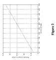
- FIG. 2 shows the normalized frequency offset of one mobile unit as a function of the velocity of the mobile unit.
- the frequency offset is normalized to the sub carrier spacing.
- the normalized frequency offset (denoted as ⁇ ) is obtained as
- the vertical axis indicates the normalized frequency offset as a percentage of the subcarrier spacing and the horizontal axis indicates the velocity in kilometers per hour.
- the normalized frequency offset at 0 kmph corresponds to the base station frequency drift and the user equipment frequency error. In FIG. 2 , the normalized frequency offset at 0 kmph is approximately 0.03 of the subcarrier spacing. However, the Doppler shift causes the normalized frequency offset to increase to approximately 23% of the subcarrier spacing at velocities of 500 kph. Furthermore, when there are two UEs travelling in opposite directions, the amount of residual frequency offset between the two UEs can be twice that of the frequency offset between a single UE and the eNodeB.
- FIGS. 3 and 4 show the impact of frequency offset on the modulation symbol in a SC-FDMA system.
- the vertical axes in these figures indicate the imaginary part of the modulation symbol and the horizontal axes indicate the real part of the modulation symbol.
- FIG. 3 shows a received signal constellation in the presence of frequency offset for QPSK modulation and a normalized frequency offset of 0.1.
- FIG. 4 shows a received signal constellation in the presence of frequency offset for 16-QAM modulation and a normalized frequency offset of 0.1.
- frequency offset introduces rotation of the signal constellation. The amount of rotation depends on the sampling rate and the symbol duration.
- Conventional wireless communication systems implement a frequency offset estimation and compensation algorithm on the receiver-side.
- the frequency offset estimation and compensation algorithms can rotate the signal approximately back to the original constellation.
- frequency offsets also exacerbate inter-carrier interference (ICI) and these effects cannot be corrected by simply applying a frequency offset estimation and compensation algorithm, at least in part because of the difficulty in separating contributions from symbols transmitted using the different carriers with different frequency offset.
- ICI inter-carrier interference
- the ICI can be significant and limit the performance of multi-user SC-FDMA system.
- the signal degradation caused by ICI may be particularly acute when users with different received SNR requirements are scheduled in adjacent subcarriers.
- FIG. 5 shows the degradation in received signal power due to frequency offset.
- the vertical axis indicates the received signal power degradation in decibels and the horizontal axis indicates the normalized frequency offset.
- ICI is assumed to be produced by a single interfering user.
- the symbol SNR of the user of interest and the symbol SNR of the interfering user are assumed to be equal.
- Increasing the normalized frequency offset causes the received signal-to-interference-plus-noise ratio (SINR) to be increasingly degraded.
- SINR received signal-to-interference-plus-noise ratio
- FIG. 6 shows the degradation in the signal-to-interference-plus-noise ratio (SINR) caused by ICI between users having a normalized frequency offset.
- SINR signal-to-interference-plus-noise ratio
- the vertical axis indicates the approximate SINR and the horizontal axis indicates the normalized frequency offset.
- FIG. 6 shows that even in the presence of small residual frequency offset, the amount of SINR degradation can be significant.
- the degradation of the SINR is larger when the SNR is large.
- the symbol constellation of the user of interest may be rotated to approximately the original constellation, conventional frequency offset estimation and compensation algorithms are not typically able to compensate for frequency offset of the interfering user. Consequently, ICI from the frequency offset signal from the interfering user may result in significant degradation in the SINR for the user of interest. This can be a limiting factor in achieving a high target data rate on the uplink in high date rate systems such as the Long Term Evolution (LTE) system.
- LTE Long Term Evolution
- the present invention is directed to addressing the effects of one or more of the problems set forth above.
- the following presents a simplified summary of the invention in order to provide a basic understanding of some aspects of the invention. This summary is not an exhaustive overview of the invention. It is not intended to identify key or critical elements of the invention or to delineate the scope of the invention. Its sole purpose is to present some concepts in a simplified form as a prelude to the more detailed description that is discussed later.
- methods are provided for wireless communication over a communication link including at least one carrier that comprises a plurality of sub-carriers.
- One embodiment of the method includes modifying at least one frequency of at least one uplink sub-carrier in response to a signal indicating a modification of the frequency.
- Another embodiment of the method includes providing a signal indicating a modification of at least one frequency of at least one uplink sub-carrier.
- FIG. 1 shows the frequency offset of one mobile unit as a function of the velocity of the mobile unit
- FIG. 2 shows the normalized frequency offset of one mobile unit as a function of the velocity of the mobile unit
- FIGS. 3 and 4 show the impact of frequency offset on the modulation symbol in a SC-FDMA system
- FIG. 5 shows the degradation in received SINR due to frequency offset
- FIG. 6 shows the degradation in the signal-to-interference-plus-noise ratio (SINR) caused by inter-carrier interference (ICI) between users having a normalized frequency offset;
- SINR signal-to-interference-plus-noise ratio
- ICI inter-carrier interference
- FIG. 7 conceptually illustrates one exemplary embodiment of a wireless communication system, in accordance with one embodiment of the present invention.
- FIGS. 8A and 8B conceptually illustrate received carrier signal frequencies, in accordance with one embodiment of the present invention.
- FIG. 9 conceptually illustrates one exemplary embodiment of a method of frequency synchronization, in accordance with one embodiment of the present invention.
- the software implemented aspects of the invention are typically encoded on some form of program storage medium or implemented over some type of transmission medium.
- the program storage medium may be magnetic (e.g., a floppy disk or a hard drive) or optical (e.g., a compact disk read only memory, or “CD ROM”), and may be read only or random access.
- the transmission medium may be twisted wire pairs, coaxial cable, optical fiber, or some other suitable transmission medium known to the art. The invention is not limited by these aspects of any given implementation.
- the wireless communication system 700 includes a base station 705 . Although a single base station 705 is depicted in the illustrated embodiment, the present invention is not limited to one base station 705 for providing wireless connectivity. In alternative embodiments, the wireless communication system 700 may include any number of the base stations 705 and/or other devices for providing wireless connectivity, such as access points, base station routers, nodes-B, e-nodes-B, and the like.
- the wireless communication system 700 operates according to Single Channel-FDMA (SC-FDMA). However, the present invention is not limited to systems that operate exclusively according to SC-FDMA.
- alternative embodiments of the wireless communication system 700 may operate according to Orthogonal Frequency Division Multiple Access (OFDMA) and/or other wireless indication protocols or standards.
- OFDMA Orthogonal Frequency Division Multiple Access
- the wireless communication system 700 also includes two mobile units 710 ( 1 - 2 ).
- the distinguishing indices ( 1 - 2 ) may be used to indicate individual mobile units 710 ( 1 - 2 ) four subsets thereof. However, the indices may be dropped when the mobile units 710 are referred to collectively. This convention may also be applied to other elements shown in the drawings and indicated by reference numerals and one or more distinguishing indices.
- the mobile units 710 ( 1 - 2 ) communicate with the base station 705 over wireless communication links (also known as air interfaces) that include an uplink (or reverse link) 715 and a downlink (or forward link) 720 .
- a band of carrier frequencies is allocated to the wireless communication link and the available frequency spectrum is then divided into a plurality of sub-carriers within the carrier frequency bandwidth.
- the available bandwidth is divided into a plurality of orthogonal subcarriers similar to OFDMA, and discrete Fourier transform (DFT) pre-coding is used to provide low Peak-to-Average-Power Ratio (PAPR) compared with OFDMA transmission.
- DFT discrete Fourier transform
- PAPR Peak-to-Average-Power Ratio
- Each sub-carrier has a selected frequency and the frequencies associated with different sub-carriers are selected to be orthogonal to each other.
- Information may then be transmitted between a base station 705 and the mobile unit 710 concurrently over one or more channels of the uplink 715 and downlink 720 that are formed using the sub-carriers.
- Frequency offsets may exist between the mobile unit 710 and a base station 705 .
- the sub-carrier frequency transmitted by the mobile unit 710 e.g., over the uplink 715
- the sub carrier frequency transmitted by the base station 705 may differ from a sub carrier frequency received at the mobile unit 710 .
- Frequency drifts and/or errors within the transmitting or receiving elements (not shown) of the mobile unit 710 and/or the base stations 705 may also contribute to the frequency offsets.
- the mobile unit 710 ( 1 ) is moving approximately towards the base station 705 , as indicated by the velocity vector 725 ( 1 ).
- the Doppler shift of the sub-carrier increases the frequency of the sub-carrier relative to the transmitted frequency of the sub-carrier.
- the mobile unit 710 ( 2 ) is moving approximately away from the base station 705 , as indicated by the velocity vector 725 ( 2 ).
- the Doppler shift of the sub-carrier decreases the frequency of the sub-carrier relative to the transmitted frequency of the sub-carrier.
- FIG. 8A conceptually illustrates the transmitted frequency 800 of the sub-carrier and the received frequency 805 .
- the vertical axis indicates the amplitude of the received signal (in arbitrary units) and the horizontal axis indicates the frequency of the sub-carrier.
- the transmitting and receiving elements are moving towards each other.
- the Doppler shift and any other frequency offsets result in the received frequency 805 being larger than the transmitted frequency 800 by a frequency error 810 .
- FIG. 8B conceptually illustrates the transmitted frequency 815 of the sub-carrier and the received frequency 820 .
- the vertical axis indicates the amplitude of the received signal (in arbitrary units) and the horizontal axis indicates the frequency of the sub-carrier.
- the transmitting and receiving elements are moving away from each other.
- the Doppler shift and any other frequency offsets result in the received frequency 820 being smaller than the transmitted frequency 815 by a frequency error 825 .
- the frequency of one or more sub-carriers may be modified to compensate for associated frequency offsets.
- the base station 705 may monitor a channel, such as a random access channel, for signals such as pilot signals transmitted by the mobile units 710 .
- a channel such as a random access channel
- the base station 705 may determine a frequency offset or error by comparing the received frequency to an expected frequency of the pilot signal. The base station 705 may then determine an appropriate correction that approximately compensates for the measured frequency offset or error and may transmit information indicating this correction to the mobile unit 710 that transmitted the received pilot signal over the random access channel.
- the mobile unit 710 may then use this correction signal to modify the frequency of one or more sub-carriers used to transmit information over the uplink 715 .
- the station 705 may determine modifications to the sub-carrier frequency periodically or in response to the measured frequency offset or error exceeding a threshold value.
- FIG. 9 conceptually illustrates one exemplary embodiment of a method 900 of frequency synchronization.
- a base station receives (at 905 ) a pilot signal from a mobile unit.
- the base station may be monitoring a random access channel and may receive (at 905 ) a pilot signal transmitted by the mobile unit over the random access channel.
- the received pilot signal may include one or more reference symbols, such as the reference symbols that may be used for channel estimation.
- the received signal may be a channel sounding reference signal, which may be used for timing and/or frequency estimation, at least in part because the channel sounding reference signal has a large bandwidth and has better timing resolution relative to other reference signals, such as a data demodulation reference signal.
- the channel sounding reference signal and the data demodulation reference signal are both defined by LTE.
- the received signal may include a cyclic prefix, such as the cyclic prefix that may be attached to orthogonal frequency division multiplexed (OFDM) signals to reduce or avoid inter-symbol interference.
- OFDM orthogonal frequency division multiplexed
- the base station may then determine (at 910 ) the frequency ( ⁇ SC ) of the subcarrier used to transmit the pilot signal.
- the received frequency ( ⁇ SC ) may not correspond to the frequency ( ⁇ 0 ) used or expected by the receiver in the base station.
- the base station may therefore determine (at 915 ) whether the received frequency ( ⁇ SC ) is equal to the frequency ( ⁇ 0 ) expected at the base station.
- the received signal may be down-modulated at the expected subcarrier frequency ( ⁇ SC ) and then the autocorrelation properties may be used to estimate the frequency offset in the equivalent complex baseband representation of the received and down-modulated signal. For example, the autocorrelation properties of reference symbols corresponding to the received pilot signal may be used to estimate the frequency offset.
- the base station may determine (at 915 ) whether the received frequency ( ⁇ SC ) is within a selected tolerance of the frequency ( ⁇ 0 ). For example, if the received frequency ( ⁇ SC ) is within the selected tolerance of the frequency ( ⁇ 0 ), then the receiver may determine that the received frequency ( ⁇ SC ) is substantially equal to the frequency ( ⁇ 0 ). However, if the received frequency ( ⁇ SC ) is not within the selected tolerance of the frequency ( ⁇ 0 ), then the receiver may determine that the received frequency ( ⁇ SC ) is not substantially equal to the frequency ( ⁇ 0 ).
- the base station may wait for additional signals from the mobile unit. For example, the base station may monitor a random access channel or other channels or sub-channels for signals that may be used to determine (at 910 ) sub-carrier frequencies associated with mobile units in communication with the base station. If the base station determines (at 915 ) that the received frequency ( ⁇ SC ) is not substantially equal to the frequency ( ⁇ 0 ), then the base station may determine (at 920 ) a sub-carrier frequency error.
- the sub-carrier frequency error may be defined as the difference between the received frequency ( ⁇ SC ) and the expected frequency ( ⁇ 0 ).
- a change in the sub-carrier frequency may then be determined (at 925 ) using the sub-carrier frequency error.
- the received frequency ( ⁇ SC ) and the expected frequency ( ⁇ 0 ) may also be used to determine (at 925 ) the change in the sub-carrier frequency.
- the change in the sub-carrier frequency may be determined (at 925 ) to be approximately equal to the difference between the received frequency ( ⁇ SC ) and the expected frequency ( ⁇ 0 ).
- the estimated frequency offset can be quantized, e.g., into quantized steps that are a selected fraction of the received frequency ( ⁇ SC ).
- the quantized value may be used to signal a quantized frequency offset to the mobile station, which then compensates for the corresponding quantized frequency offset.
- the residual frequency offset (residual error) after frequency compensation may be limited to a value that is less than the quantization stepsize.
- the base station may then provide (at 930 ) a signal to the mobile unit indicating a modified sub-carrier frequency.
- the signal may be a Frequency Advance signal that includes information indicating the value of the sub-carrier frequency that should be used by the mobile unit.
- the Frequency Advance signal may include information indicating a change in the sub-carrier frequency that should be used by the mobile unit to modify the subcarriers. The change may be indicated as a frequency shift, a percentage change in the frequency, a frequency step (in the case when the possible subcarrier frequencies are predetermined and known to the mobile unit), and the like.
- the mobile unit may utilize the signal from the base station to modify one or more sub-carrier frequencies to improve frequency synchronization between the mobile unit and the base station.
- the Frequency Advance signal may be transmitted to the mobile station on a random access channel with a Timing Advance signal prior to initialization of dedicated communication channels between the mobile unit and the base station.
- the pilot signal transmitted on a random access channel is used to estimate frequency errors and/or offsets that are used for frequency synchronization.
- the present invention is not limited to use of the pilot signal.
- dedicated communication channels or sub-channels may already be formed between the mobile unit and the base station. Signals transmitted on these communication channels or sub-channels may therefore be used to determine (at 910 ) the frequency ( ⁇ SC ) of the subcarrier used to transmit the signals on these communication channels or sub-channels.
- a closed-loop frequency synchronization mechanism may therefore be implemented to maintain frequency synchronization during communications between the mobile unit and the base station.
- the base station may periodically determine (at 910 ) the frequency ( ⁇ SC ) of the subcarrier used to transmit the signals on the established communication channels or sub-channels.
- the determined frequency ( ⁇ SC ) may then be used to synchronize frequencies, as discussed above.
- the base station may monitor the frequency ( ⁇ SC ) of the subcarrier and may initiate the frequency synchronization procedure described herein in response to the frequency ( ⁇ SC ) of the subcarrier differing from the expected frequency ( ⁇ 0 ) by a selected value or fractional value.
Abstract
Description
f offset =Δf BS +Δf UE+2×f Doppler
where ΔfBS, ΔfUE, and fDoppler
The vertical axis indicates the normalized frequency offset as a percentage of the subcarrier spacing and the horizontal axis indicates the velocity in kilometers per hour. The normalized frequency offset at 0 kmph corresponds to the base station frequency drift and the user equipment frequency error. In
f offset =Δf BS +Δf UE+2×f Doppler
where ΔfBS, ΔfUE, and fDoppler
Claims (16)
Priority Applications (1)
| Application Number | Priority Date | Filing Date | Title |
|---|---|---|---|
| US11/668,311 US8942222B2 (en) | 2007-01-29 | 2007-01-29 | Frequency synchronization in wireless communication systems |
Applications Claiming Priority (1)
| Application Number | Priority Date | Filing Date | Title |
|---|---|---|---|
| US11/668,311 US8942222B2 (en) | 2007-01-29 | 2007-01-29 | Frequency synchronization in wireless communication systems |
Publications (2)
| Publication Number | Publication Date |
|---|---|
| US20080182582A1 US20080182582A1 (en) | 2008-07-31 |
| US8942222B2 true US8942222B2 (en) | 2015-01-27 |
Family
ID=39668576
Family Applications (1)
| Application Number | Title | Priority Date | Filing Date |
|---|---|---|---|
| US11/668,311 Expired - Fee Related US8942222B2 (en) | 2007-01-29 | 2007-01-29 | Frequency synchronization in wireless communication systems |
Country Status (1)
| Country | Link |
|---|---|
| US (1) | US8942222B2 (en) |
Cited By (1)
| Publication number | Priority date | Publication date | Assignee | Title |
|---|---|---|---|---|
| US20150257149A1 (en) * | 2014-03-10 | 2015-09-10 | Hon Hai Precision Industry Co., Ltd. | Femtocell and method of adjusting frequency |
Families Citing this family (13)
| Publication number | Priority date | Publication date | Assignee | Title |
|---|---|---|---|---|
| KR100965673B1 (en) * | 2006-11-15 | 2010-06-24 | 삼성전자주식회사 | A method for transmitting and receiving in a communication system |
| US8401561B2 (en) * | 2007-03-22 | 2013-03-19 | Telefonaktiebolaget Lm Ericsson (Publ) | Method and arrangement in a telecommunication system |
| JP5042320B2 (en) | 2007-03-29 | 2012-10-03 | エルジー エレクトロニクス インコーポレイティド | Sounding reference signal transmission method in wireless communication system |
| GB0708345D0 (en) * | 2007-04-30 | 2007-06-06 | Nokia Siemens Networks Oy | Signalling within a communication system |
| KR101380558B1 (en) | 2007-06-19 | 2014-04-02 | 엘지전자 주식회사 | Method of Transmitting Sounding Reference Signal |
| KR101397039B1 (en) * | 2007-08-14 | 2014-05-20 | 엘지전자 주식회사 | Signal Transmission Method Using CDM Against The Effect Of Channel Estimation Error in Transmit Diversity System |
| RU2439809C2 (en) | 2007-08-14 | 2012-01-10 | Эл Джи Электроникс Инк. | Method of acquiring resource region information for phich and method of receiving pdcch |
| KR101430267B1 (en) * | 2007-08-14 | 2014-08-18 | 엘지전자 주식회사 | Method of Transmitting Data in a Wireless Communication System |
| KR101405974B1 (en) * | 2007-08-16 | 2014-06-27 | 엘지전자 주식회사 | Methods for transmitting codewords in multiple input multiple output system |
| KR101507785B1 (en) | 2007-08-16 | 2015-04-03 | 엘지전자 주식회사 | A method for transmitting channel quality information in a MIMO (Multiple Input Multiple Output) system |
| CN102612162B (en) * | 2008-01-07 | 2015-09-09 | 三星电子株式会社 | The equipment of transmitting random access preamble signal and method |
| US9660775B2 (en) * | 2010-06-15 | 2017-05-23 | Huawei Technologies Co., Ltd. | System and method for punctured pilot transmission in a wireless network |
| IT201900002785A1 (en) * | 2019-02-26 | 2020-08-26 | Teko Telecom S R L | BASE RADIO STATION AND WIRELESS TELECOMMUNICATION PROCESS FOR HIGH MOBILITY SCENARIOS |
Citations (13)
| Publication number | Priority date | Publication date | Assignee | Title |
|---|---|---|---|---|
| US5604768A (en) * | 1992-01-09 | 1997-02-18 | Cellnet Data Systems, Inc. | Frequency synchronized bidirectional radio system |
| US5991344A (en) * | 1996-06-14 | 1999-11-23 | Kabushiki Kaisha Toshiba | Mobile communication device and method for setting AFC initial value |
| US20020101840A1 (en) * | 2000-11-29 | 2002-08-01 | Stefan Davidsson | Timing drift compensation in wireless packet-based systems |
| US20040076239A1 (en) * | 2002-10-22 | 2004-04-22 | Hee-Jung Yu | Apparatus and method for tracking residual frequency offset for single carrier-frequency domain equalizer system |
| US20040076246A1 (en) * | 2002-10-21 | 2004-04-22 | Stmicroelectronics Nv | Methods and apparatus for synchronization of training sequences |
| US20050025042A1 (en) * | 1999-09-20 | 2005-02-03 | Zion Hadad | Bi-directional communication channel |
| US20050147188A1 (en) * | 2003-12-30 | 2005-07-07 | Hong Liu | Frequency control for a mobile communications device |
| US6985432B1 (en) * | 2000-01-28 | 2006-01-10 | Zion Hadad | OFDM communication channel |
| US6985705B2 (en) * | 1999-08-10 | 2006-01-10 | Broadcom Corporation | Radio frequency control for communication systems |
| US20060239368A1 (en) * | 2005-04-11 | 2006-10-26 | Samsung Electronics Co., Ltd. | Apparatus and method for estimating frequency offset in Orthogonal Frequency Division Multiplexing system |
| US7170943B1 (en) * | 2000-06-30 | 2007-01-30 | Soma Networks, Inc. | Control channel for a wireless digital subscriber line system |
| US20090129495A1 (en) * | 2004-06-25 | 2009-05-21 | Yongseok Jin | Allocation of radio resource in orthogonal frequency division multiplexing system |
| US20090141700A1 (en) * | 2005-10-21 | 2009-06-04 | Robert Baldemair | Technique for performing a random access procedure over a radio interface |
-
2007
- 2007-01-29 US US11/668,311 patent/US8942222B2/en not_active Expired - Fee Related
Patent Citations (13)
| Publication number | Priority date | Publication date | Assignee | Title |
|---|---|---|---|---|
| US5604768A (en) * | 1992-01-09 | 1997-02-18 | Cellnet Data Systems, Inc. | Frequency synchronized bidirectional radio system |
| US5991344A (en) * | 1996-06-14 | 1999-11-23 | Kabushiki Kaisha Toshiba | Mobile communication device and method for setting AFC initial value |
| US6985705B2 (en) * | 1999-08-10 | 2006-01-10 | Broadcom Corporation | Radio frequency control for communication systems |
| US20050025042A1 (en) * | 1999-09-20 | 2005-02-03 | Zion Hadad | Bi-directional communication channel |
| US6985432B1 (en) * | 2000-01-28 | 2006-01-10 | Zion Hadad | OFDM communication channel |
| US7170943B1 (en) * | 2000-06-30 | 2007-01-30 | Soma Networks, Inc. | Control channel for a wireless digital subscriber line system |
| US20020101840A1 (en) * | 2000-11-29 | 2002-08-01 | Stefan Davidsson | Timing drift compensation in wireless packet-based systems |
| US20040076246A1 (en) * | 2002-10-21 | 2004-04-22 | Stmicroelectronics Nv | Methods and apparatus for synchronization of training sequences |
| US20040076239A1 (en) * | 2002-10-22 | 2004-04-22 | Hee-Jung Yu | Apparatus and method for tracking residual frequency offset for single carrier-frequency domain equalizer system |
| US20050147188A1 (en) * | 2003-12-30 | 2005-07-07 | Hong Liu | Frequency control for a mobile communications device |
| US20090129495A1 (en) * | 2004-06-25 | 2009-05-21 | Yongseok Jin | Allocation of radio resource in orthogonal frequency division multiplexing system |
| US20060239368A1 (en) * | 2005-04-11 | 2006-10-26 | Samsung Electronics Co., Ltd. | Apparatus and method for estimating frequency offset in Orthogonal Frequency Division Multiplexing system |
| US20090141700A1 (en) * | 2005-10-21 | 2009-06-04 | Robert Baldemair | Technique for performing a random access procedure over a radio interface |
Cited By (2)
| Publication number | Priority date | Publication date | Assignee | Title |
|---|---|---|---|---|
| US20150257149A1 (en) * | 2014-03-10 | 2015-09-10 | Hon Hai Precision Industry Co., Ltd. | Femtocell and method of adjusting frequency |
| US9258819B2 (en) * | 2014-03-10 | 2016-02-09 | Hon Hai Precision Industry Co., Ltd. | Femtocell and method of adjusting frequency |
Also Published As
| Publication number | Publication date |
|---|---|
| US20080182582A1 (en) | 2008-07-31 |
Similar Documents
| Publication | Publication Date | Title |
|---|---|---|
| US8942222B2 (en) | Frequency synchronization in wireless communication systems | |
| US10700840B2 (en) | Control and data signaling in SC-FDMA communication systems | |
| US20210075572A1 (en) | Method and apparatus for generating pilot tone in orthogonal frequency division multiplexing access system, and method and apparatus for estimating channel using it | |
| CN101563899B (en) | Uplink inter-carrier interference cancellation for OFDMA systems | |
| EP1956771B1 (en) | Wireless communication system and wireless communication method | |
| US20120087393A1 (en) | Reference symbol structure for dft spread ofdm system | |
| EP1596525A1 (en) | Hybrid wireless communications system | |
| JP6555827B2 (en) | Communication device and communication method | |
| US20110243190A1 (en) | Mobile terminal apparatus, base station apparatus and method for transmitting shared channel signal | |
| WO2016207607A1 (en) | Transmitter and receiver and methods of transmitting and receiving | |
| US20110096867A1 (en) | Method and Apparatus for Providing Pilot Signals in OFDM Frames | |
| US8036190B2 (en) | Methods and devices for allocating data in a wireless communication system | |
| US20090168811A1 (en) | Method of signal multiplexing and transmitter in radio communication system | |
| KR100646553B1 (en) | Method and apparatus for multi-carrier transmission | |
| EP2129035A1 (en) | Improved pilot allocation in multi-carrier systems with frequency notching | |
| WO2009069088A2 (en) | Ici cancellation apparatus and method for ofdm systems | |
| EP2129036B1 (en) | Improved pilot allocation in multi-carrier systems with frequency notching |
Legal Events
| Date | Code | Title | Description |
|---|---|---|---|
| AS | Assignment |
Owner name: LUCENT TECHNOLOGIES, INC., NEW JERSEY Free format text: ASSIGNMENT OF ASSIGNORS INTEREST;ASSIGNORS:BACHL, RAINER;LEE, JUNG A.;REEL/FRAME:018820/0474 Effective date: 20070125 |
|
| AS | Assignment |
Owner name: CREDIT SUISSE AG, NEW YORK Free format text: SECURITY INTEREST;ASSIGNOR:ALCATEL-LUCENT USA INC.;REEL/FRAME:030510/0627 Effective date: 20130130 |
|
| AS | Assignment |
Owner name: ALCATEL-LUCENT USA INC., NEW JERSEY Free format text: MERGER;ASSIGNOR:LUCENT TECHNOLOGIES INC.;REEL/FRAME:031087/0026 Effective date: 20081101 |
|
| FEPP | Fee payment procedure |
Free format text: PAYOR NUMBER ASSIGNED (ORIGINAL EVENT CODE: ASPN); ENTITY STATUS OF PATENT OWNER: LARGE ENTITY |
|
| AS | Assignment |
Owner name: ALCATEL-LUCENT USA INC., NEW JERSEY Free format text: RELEASE BY SECURED PARTY;ASSIGNOR:CREDIT SUISSE AG;REEL/FRAME:033949/0016 Effective date: 20140819 |
|
| STCF | Information on status: patent grant |
Free format text: PATENTED CASE |
|
| AS | Assignment |
Owner name: ALCATEL LUCENT, FRANCE Free format text: ASSIGNMENT OF ASSIGNORS INTEREST;ASSIGNOR:ALCATEL-LUCENT USA INC.;REEL/FRAME:034694/0604 Effective date: 20150108 |
|
| MAFP | Maintenance fee payment |
Free format text: PAYMENT OF MAINTENANCE FEE, 4TH YEAR, LARGE ENTITY (ORIGINAL EVENT CODE: M1551) Year of fee payment: 4 |
|
| FEPP | Fee payment procedure |
Free format text: MAINTENANCE FEE REMINDER MAILED (ORIGINAL EVENT CODE: REM.); ENTITY STATUS OF PATENT OWNER: LARGE ENTITY |
|
| LAPS | Lapse for failure to pay maintenance fees |
Free format text: PATENT EXPIRED FOR FAILURE TO PAY MAINTENANCE FEES (ORIGINAL EVENT CODE: EXP.); ENTITY STATUS OF PATENT OWNER: LARGE ENTITY |
|
| STCH | Information on status: patent discontinuation |
Free format text: PATENT EXPIRED DUE TO NONPAYMENT OF MAINTENANCE FEES UNDER 37 CFR 1.362 |
|
| FP | Lapsed due to failure to pay maintenance fee |
Effective date: 20230127 |