US9035572B1 - Combined lighting device with an integrated dimming control system - Google Patents

Combined lighting device with an integrated dimming control system Download PDF

Info

Publication number
US9035572B1
US9035572B1 US13/762,186 US201313762186A US9035572B1 US 9035572 B1 US9035572 B1 US 9035572B1 US 201313762186 A US201313762186 A US 201313762186A US 9035572 B1 US9035572 B1 US 9035572B1
Authority
US
United States
Prior art keywords
zone
lighting
scene
zones
settings
Prior art date
Legal status (The legal status is an assumption and is not a legal conclusion. Google has not performed a legal analysis and makes no representation as to the accuracy of the status listed.)
Active, expires
Application number
US13/762,186
Inventor
Patrick S. Dolan
Current Assignee (The listed assignees may be inaccurate. Google has not performed a legal analysis and makes no representation or warranty as to the accuracy of the list.)
Dolan Designs Inc
Original Assignee
Dolan Designs Inc
Priority date (The priority date is an assumption and is not a legal conclusion. Google has not performed a legal analysis and makes no representation as to the accuracy of the date listed.)
Filing date
Publication date
Application filed by Dolan Designs Inc filed Critical Dolan Designs Inc
Priority to US13/762,186 priority Critical patent/US9035572B1/en
Assigned to Dolan Designs Incorporated reassignment Dolan Designs Incorporated ASSIGNMENT OF ASSIGNORS INTEREST (SEE DOCUMENT FOR DETAILS). Assignors: DOLAN, PATRICK S.
Priority to US14/695,464 priority patent/US9538622B1/en
Application granted granted Critical
Publication of US9035572B1 publication Critical patent/US9035572B1/en
Priority to US15/392,216 priority patent/US9907149B1/en
Priority to US15/870,515 priority patent/US10278269B2/en
Priority to US16/172,000 priority patent/US10813199B2/en
Priority to US17/074,266 priority patent/US11466828B2/en
Active legal-status Critical Current
Adjusted expiration legal-status Critical

Links

Images

Classifications

    • H05B37/02
    • HELECTRICITY
    • H05ELECTRIC TECHNIQUES NOT OTHERWISE PROVIDED FOR
    • H05BELECTRIC HEATING; ELECTRIC LIGHT SOURCES NOT OTHERWISE PROVIDED FOR; CIRCUIT ARRANGEMENTS FOR ELECTRIC LIGHT SOURCES, IN GENERAL
    • H05B47/00Circuit arrangements for operating light sources in general, i.e. where the type of light source is not relevant
    • H05B47/10Controlling the light source
    • H05B47/175Controlling the light source by remote control
    • H05B47/19Controlling the light source by remote control via wireless transmission
    • FMECHANICAL ENGINEERING; LIGHTING; HEATING; WEAPONS; BLASTING
    • F21LIGHTING
    • F21SNON-PORTABLE LIGHTING DEVICES; SYSTEMS THEREOF; VEHICLE LIGHTING DEVICES SPECIALLY ADAPTED FOR VEHICLE EXTERIORS
    • F21S8/00Lighting devices intended for fixed installation
    • F21S8/04Lighting devices intended for fixed installation intended only for mounting on a ceiling or the like overhead structures
    • F21S8/06Lighting devices intended for fixed installation intended only for mounting on a ceiling or the like overhead structures by suspension
    • FMECHANICAL ENGINEERING; LIGHTING; HEATING; WEAPONS; BLASTING
    • F21LIGHTING
    • F21VFUNCTIONAL FEATURES OR DETAILS OF LIGHTING DEVICES OR SYSTEMS THEREOF; STRUCTURAL COMBINATIONS OF LIGHTING DEVICES WITH OTHER ARTICLES, NOT OTHERWISE PROVIDED FOR
    • F21V21/00Supporting, suspending, or attaching arrangements for lighting devices; Hand grips
    • F21V21/008Suspending from a cable or suspension line
    • HELECTRICITY
    • H02GENERATION; CONVERSION OR DISTRIBUTION OF ELECTRIC POWER
    • H02JCIRCUIT ARRANGEMENTS OR SYSTEMS FOR SUPPLYING OR DISTRIBUTING ELECTRIC POWER; SYSTEMS FOR STORING ELECTRIC ENERGY
    • H02J3/00Circuit arrangements for ac mains or ac distribution networks
    • HELECTRICITY
    • H05ELECTRIC TECHNIQUES NOT OTHERWISE PROVIDED FOR
    • H05BELECTRIC HEATING; ELECTRIC LIGHT SOURCES NOT OTHERWISE PROVIDED FOR; CIRCUIT ARRANGEMENTS FOR ELECTRIC LIGHT SOURCES, IN GENERAL
    • H05B35/00Electric light sources using a combination of different types of light generation
    • HELECTRICITY
    • H05ELECTRIC TECHNIQUES NOT OTHERWISE PROVIDED FOR
    • H05BELECTRIC HEATING; ELECTRIC LIGHT SOURCES NOT OTHERWISE PROVIDED FOR; CIRCUIT ARRANGEMENTS FOR ELECTRIC LIGHT SOURCES, IN GENERAL
    • H05B47/00Circuit arrangements for operating light sources in general, i.e. where the type of light source is not relevant
    • H05B47/10Controlling the light source
    • H05B47/175Controlling the light source by remote control
    • H05B47/19Controlling the light source by remote control via wireless transmission
    • H05B47/195Controlling the light source by remote control via wireless transmission the transmission using visible or infrared light

Definitions

  • the present invention generally relates to a lighting device with a master dimming control system enclosed with the lighting device. More particularly, the lighting device has a plurality of lighting effects, scenes and zones controlled by one or more remote control switches.
  • Prior art multi-zone multi-scene lighting controls have not been designed to control one lighting device in a room but rather a group of lights selected, and the lighting design for such a system usually requires the expertise of a professional lighting specialist who has been trained.
  • a typical installation over a table might include a pair of recessed lights mounted four feet apart and centered on the chandelier and the table, which would then provide task lighting or direct lighting on the table (zone 1).
  • Another recessed light would be installed to accent a centerpiece arrangement that would later be placed directly under the chandelier (zone 2), while another couple of recessed lights would be positioned to direct light at art work in the room (zone 3).
  • a chandelier would be installed, centered on the table (zone 4).
  • Lighting effects such as general area lighting, accent lighting, task lighting and are often used in lighting the interiors of residential and commercial spaces.
  • Grazing as a lighting effect is commonly used in interior design in order to accentuate the architecture of a residence or commercial building. This is accomplished by placing a light source close to the plane of a wall and then directing the light beam obliquely across the wall's surface. Grazing is a particularly dramatic way to highlight the texture of a stone or brick wall by creating shadows.
  • One aspect of the invention is a multi-zone, multi-scene dimming system that does not require installing new wiring in the walls or ceiling. With this invention no special wiring is required. For example, you could install the wall remote in place of an existing single-pole switch that controls a lighting device such as a chandelier.
  • the wall remote would fit in the same switch box and fit inside a decora style switch plate.
  • This wall-mounted remote would preferably have at least four actuators for selecting different scenes as well as an on/off button. There would be an antenna in or coupled to the remote.
  • Another aspect of the invention is incorporation of several different lighting techniques such as general area lighting, task lighting, grazing, indirect lighting and accent lighting into the support structure of a single lighting device wherein a multi-zone multi-scene dimming system is built into the base or body of the single device such as a chandelier, ceiling light, floor lamp, wall mounted light or ceiling fan.
  • a multi-zone multi-scene dimming system is built into the base or body of the single device such as a chandelier, ceiling light, floor lamp, wall mounted light or ceiling fan.
  • General area lighting provides light without concern for directing the light in any specific direction, lighting the general area without placing any focus on any features in the area, whereas task lighting provides bright lighting direct to a specific surface such as a dining room table or conference room table or rug. Ninety percent of the light is directed downward.
  • accent lighting for a lighting device is directed narrowly at a specific object such as a flower arrangement or statue centered directly under the center of the chandelier or at a piece of artwork on an adjacent wall.
  • Another aspect of the invention is to be able to offer a lighting device that has multiple scenes with layered lighting effects such as general area lighting, task lighting, grazing and accent lighting that can all be pre-programmed and easily selected.
  • Scenes are defined by different combinations of on/off and/or intensity conditions and fade rates of the zones.
  • a lighting zone is defined by one or more light sources that are commonly controlled. For example, consider a four scene system wherein zone 1 is defined by a lighting device with a plurality of general area lights, zone 2 is defined by a plurality of task lights, zone 3 is defined by a plurality of accent lights and zone 4 is defined by indirect lighting.
  • Various on/off and intensity combinations of the zones may be imagined, each of which defines one possible scene.
  • scene 1 might be defined by zone 1 (a plurality of general area lights) 10% intensity, zone 2 (plurality of task lights) at say, 50% intensity, zone 3 off and zone 4 (indirect lighting) at 20%.
  • Each scene may be selected by depressing on one of the scene select options on one of the different remotes, or all zones may be turned off by depressing an off button as is common.
  • the defined scenes are stored in a master dimming control memory, together with a fade time representing a desired time for effecting a change from existing intensity for each zone in the most recently selected scene to the desired intensity for each zone in the currently selected scene.
  • controls can be provided for color changes, e.g., drivers for selecting combinations of different color LEDs used as light sources in one or more zones.
  • Each scene can be preset at the factory; also fade rates can be preset at the factory.
  • One or more of the lighting devices are capable of being networked so they can operate with the same remote and can be turned on and off as well as display the same scenes when a given scene selection is made.
  • Each system can be controlled and programmed from a remote control.
  • a remote control could be installed in a standard single gang wall box and/or a hand-held or table top remote could be used.
  • a switch for an entry chandelier often is in a multi-gang box with a three or four-gang switch plates and other switches located adjacent to the entry chandelier switch.
  • This invention allows the entryway switch to be replaced with a wall-mounted remote control that fits in a standard single gang box and in one gang of a decora plate.
  • Another aspect of the invention is an ability to provide a multi-scene lighting device with a selling demonstration mode incorporated in the master dimming control of the lighting device that will allow each of scenes to continually cycle. For instance in a four-scene program, if it was on scene 1, it could remain at scene 1 for 10 seconds, then cycle to scene 2 and stay there for 10 seconds and then cycle to scene 3 for 10 seconds and then cycle to scene 4 for 10 seconds and then turn off for 10 seconds and go back to scene 1, continually recycling through the different scenes in a loop.
  • FIG. 2 shows a master dimming system, which would preferably include communications module, such as an Echelon transceiver, connected to the circuit board inside the unit. There can be at least one transceiver for each lighting channel.
  • Each chipset using wireless and/or power line technology can be individually addressable and can have a dimming module connected to it, if the electrical device is dimmable, otherwise it would just turn on and off.
  • the master dimming control system would be either installed inside part of the lighting device such as the canopy of a chandelier or the body of the lighting device. Alternately, more than one master dimming control could be installed in a lighting device.
  • the master dimming control can be a unitary module incorporating both control and communication circuitry and dimmers or its components can be distributed in different parts of the lighting device, for example, the canopy, and body of a chandelier.
  • a hard wired remote that would be capable of sending a signal over standard house wire using an Echelon power line smart transceivers to the master control panel or alternately by an infrared remote or a radio frequency remote that is wall mounted or handheld.
  • both power line technology and wireless might be used.
  • the invention can be hard-wired using three-wires (i.e., having connections to the hot, dimmed hot and neutral lines) or as a two wire system. It will work on a switched leg.
  • the wall mounted controls will work with single pole, 3-way and 4-way installations.
  • the remote units are preferably provided with manual controls for selecting different scenes and/or for temporarily raising or lowering the intensity of all zones simultaneously.
  • the manual controls can include dedicated push buttons, state-selectable buttons and soft-keys, a touch-screen displaying buttons or a combination thereof.
  • a feature of this device would be that it has a plurality of zones of lighting whereby different zones can be mixed to create different scenes.
  • Another feature of the remote control is that the remote control would be fully programmable.
  • the end user would like to change one or more of the pre-set scenes or fade rates set at the factory, it can be accomplished from the remote controllers or on the master control panel.
  • the invention enables a single lighting device that incorporates several lighting effects, such as general area lighting, down lighting, accent lighting, grazing, and indirect lighting and a plurality of up lighting each wired to different zones so that each type of lighting effect could be mixed to create different scenes of lighting.
  • several lighting effects such as general area lighting, down lighting, accent lighting, grazing, and indirect lighting and a plurality of up lighting each wired to different zones so that each type of lighting effect could be mixed to create different scenes of lighting.
  • FIG. 1 is a block diagram of a conventional single dimmer circuit.
  • FIG. 2 is a block diagram of a conventional multiple dimmer circuit.
  • FIG. 3 is a block diagram of an embodiment of the invention providing remote scene control of multiple lighting zones in a lighting fixture.
  • FIG. 4 is a block diagram of another embodiment of the invention providing remote scene control of multiple lighting zones in a lighting fixture which includes low voltage lighting elements.
  • FIG. 5 is a block diagram of an embodiment of a dimming control keypad that can be used in the embodiments of FIGS. 3 and 4 .
  • FIG. 6 is a schematic of an example of a keypad microprocessor for use in the keypad of FIG. 5 .
  • FIG. 7 is a schematic of an example of a keypad switch matrix for use in the keypad of FIG. 5 .
  • FIG. 8 is a schematic of an example of a wireless communications module for use in the keypad of FIG. 5 .
  • FIG. 9 is a schematic of an example of a powerline communications module for use in the keypad of FIG. 5 .
  • FIG. 10 is a schematic of an example of a keypad power supply for use in the keypad of FIG. 5 .
  • FIG. 11 is a schematic of an example of a master dimming controller microprocessor for use as the scene controller in the embodiments of FIGS. 3 and 4 .
  • FIG. 12 is a schematic of an example of an array of zone dimmer circuits used in the master dimming controller microprocessor circuit of FIG. 11 .
  • FIG. 13 is a schematic of an example of zero cross detection circuit used in the master dimming controller microprocessor circuit of FIG. 11 .
  • FIG. 14 is a schematic of an example of a powerline communications module for use in the master dimming controller of FIGS. 3 and 4 .
  • FIG. 15 is a schematic of an example of a wireless communications module for use in the master dimming controller of FIGS. 3 and 4 .
  • FIG. 16 is a schematic of an example of a power supply for use in the master dimming controller of FIGS. 3 and 4 .
  • FIG. 17 is a perspective view of one embodiment of a lighting device, in this case a modern-style chandelier, incorporating multiple zones of lighting in a single support structure to create different scenes based on different combinations of the various zones and their settings in accordance with the invention.
  • FIGS. 18 and 19 are side and end elevation views of the lighting device of FIG. 17 .
  • FIGS. 20 and 21 are top and bottom plan views of the lighting device of FIG. 17 .
  • FIG. 22 is a cross-sectional view of the lighting device of FIG. 17 .
  • FIG. 23 is a side-elevation view of a second embodiment of a lighting device according to the invention, in this case the support structure of a ceiling fan-lamp, with partial cutaways to show interior structure.
  • FIGS. 24-28 are elevation views similar to FIG. 23 showing details of wiring from the master dimming controller to each of the zones.
  • FIG. 29 is a composite of elevation and plan views of the elements of a third embodiment of a lighting device, in this case a classical-style chandelier, incorporating multiple zones of lighting in a single support structure, with partial cutaways to show interior structure.
  • FIG. 30 is a wiring diagram for the lighting device of FIG. 29 .
  • FIGS. 31-38 are elevation views of the lighting device of FIG. 29 showing details of wiring from the master dimming controller to each of the zones.
  • a lighting Scene is a group of Lighting Zones wherein each Zone's illumination level is determined by its respective dimmer.
  • a lighting Zone consists of one or more light sources or elements such as an incandescent lamps, halogen lamps or light emitting diodes whose illumination level is commonly controlled by a single dimmer.
  • a lighting zone can also be a motor, as in a ceiling fan, with direction and speed controls.
  • FIG. 1 exemplifies the prior art of a single dimmer 102 installed in a single gang electrical box controlling a single light fixture 105 .
  • This is representative of the most common existing wiring in residential buildings.
  • the single A.C. Hot wire 104 precludes the dimmer from controlling more than one lighting zone.
  • An existing residence wired in this configuration would require substantial and expensive remodeling of the existing wiring enclosed within the wall and ceiling spaces.
  • FIG. 2 exemplifies the prior art of multiple wall mounted dimmers controlling multiple lighting zones. This is representative of common existing wiring in residential buildings for multiple dimmers. In this configuration, existing residences are precluding from changing the location of or adding additional lighting zones without extensive remodeling.
  • FIG. 3 exemplifies the dimming control improvements over the prior art wiring limitations shown in FIG. 1 and FIG. 2 .
  • a Master Dimmer Controller 310 is mounted within the physical support structure of a lighting device 311 . Electrical power for the lighting device 311 is provided by a single A.C. circuit consisting of a A.C. Hot wire 303 , A.C. Neutral wire 302 and safety ground wire (not shown).
  • the Master Dimmer Controller 310 allows for a plurality of individually controlled dimmable lighting zones powered by a single A.C. circuit.
  • a wall mounted or portable keypad or remote control device 312 transmits digital information containing the illumination level for each lighting zone to the Master Dimmer Controller 310 via the Communication Link 304 .
  • the Communication Link 304 may be implemented in any of a plurality of wireless media including Radio Frequency (R.F.), Infrared Light (I.R.), Data over Power Line, or a directly wired connection.
  • the remote control device can be a special-purpose device or can be implemented by software in a smart-phone using, e.g., BLUETOOTH® communications.
  • the Zone Dimmers 308 may support the electrical and dimming requirements of a multitude of lighting technologies such as incandescent lamps, low voltage halogen lamps, or L.E.D. lamps.
  • Each Light Fixture Zone 309 has at least one lamp or other lighting element.
  • a lighting device with an integrated multiple zone dimming controller enables existing residential or commercial lighting fixtures to be retrofitted with an advanced lighting fixtures capable of providing advanced lighting architecture solutions without modifying the preexisting wiring.
  • FIG. 4 is an example of a generic lighting device consisting of an integrated Master Dimming Controller 402 , six independently dimmable Zone Dimmers 405 .
  • the lighting fixture utilizes three illumination technologies in six zones: Zone 1 three incandescent lamps 401 ; Zone 2 three low voltage halogen lamps 407 ; Zone 3 two incandescent lamps; Zone 4 three L.E.D. lamps 409 ; Zone 5 eight incandescent lamps; Zone 6 four incandescent lamps.
  • FIG. 5 is a block diagram of a typical wall mounted keypad for use in system 301 .
  • the microcontroller 508 detects and processes keypad 504 switch closures and transmits the state of each keypad switch to Master Dimmer Controller 310 via Communications Module 502 .
  • FIG. 6 is an example implementation of the keypad microcontroller circuit.
  • Microcontroller 601 such as a Microchip Technology microprocessor part number PIC18F4321, is programmed by interfacing the Programming Test Points 602 with a compatible programming device such as a Microchip Technology PICKIT3, ICD3 or RealICE.
  • the microcontroller 601 program scans the rows and columns of the keypad button matrix by sequentially setting one of the Key_Col — 0 through Key Col — 3 output pins to a logical ‘1’ (+5V) while the others are set to a logical ‘0’ (0V).
  • Each Key_Row — 0 through Key_Row — 3 input pins are read into a memory location indicating the current state of each of four buttons in the respective column.
  • FIG. 7 depicts the keypad button matrix.
  • the Mode field shall be toggled from a ‘0’ to a ‘1’ or a ‘1’ to a ‘0’ to indicate the mode is in Programming or Normal mode respectively.
  • the Scene button initiating the Programming mode shall be reported to the Master Dimming Controller in the Keypad Data Payload.
  • the microcontroller 601 program periodically reports the following Keypad data shown in TABLE 1 below to the Master Dimming Controller:
  • FIG. 7 is an example of a common industry practice combining a plurality of switches into a matrix of rows and columns to reduce the total number of I/O pins required to read each switch.
  • switch contact 701 forms a unique switch (button).
  • Isolation diodes 702 allow the microcontroller to detect multiple simultaneous switch closures. Detecting two or more simultaneous switch closures allows the microcontroller to implement alternative functionality.
  • FIG. 8 is an implementation of the keypad to use a Master Dimmer Controller communications link using, for example, an industry standard Wi-Fi 802.11b communications module 801 , Microchip Technology part number MRFWBOMA.
  • the MRFWBOMA module is controlled by the keypad microcontroller 601 via an industry standard SPI serial data interface port.
  • the module 801 has serial data input port 802 and serial data output port 803 .
  • FIG. 9 is an implementation of the keypad to use a Master Dimmer Controller communications link implemented using Echelon Corporation's Power Line Communications technology, Echelon P/N PL3170.
  • the PL3170 power line module is controlled by the keypad microcontroller 601 via an industry standard SPI serial data I/O interface port 904 , 905 .
  • FIG. 10 is a commonly used power supply implementation.
  • Transformer 1003 reduces the 110 volt A.C. input via lines 1001 , 1002 to 10 volts.
  • A.C. Bridge rectifier 1004 and capacitor C 11 convert the A.C. voltage to an unregulated, filtered D.C. voltage.
  • the linear voltage regulator 1005 converts the unregulated D.C. voltage to a fixed +5 volt output to power the remaining keypad components.
  • FIG. 11 is a block diagram of a Master Dimming Controller. This exemplary implementation uses a Microchip Technology PIC18F2321 microcontroller 1101 .
  • the microcontroller 1101 receives the keypad switch state data via the Communications Module 1105 .
  • the serial data interface 1106 is an industry standard SPI serial data interface.
  • each lighting fixture's ID “DIP” switch 1108 is set to a unique four binary bit combination.
  • the default setting for the “DIP” switch is 0000.
  • the microcontroller 1101 has internal non-volatile EEPROM memory which stores the illumination level for each of the dimming zones 1107 . In the event of a power failure optionally all zones will return to the factory settings.
  • the Master Dimming Controller microcontroller either polls for or is interrupted by the communication module's reception of a Keypad data payload. Upon receipt of the payload, the Master Dimming Controller compares the received “Target Light Fixture ID” to the value of the DIP Switch 1108 . If the values match, the Master Dimming Controller parses the remainder of the received data payload.
  • the Controller retrieves the respective Scene's Zone illumination from the non-volatile and sets all zone illumination levels respectively. If more than one Scene Button is determined to be in the “Make” condition, the remaining Scene Buttons are ignored.
  • Keypad Data Payload bit field “Mode” is set to ‘1’, programming mode is enabled.
  • the keypad switches K 1 -K 5 are remapped to different functions as shown in TABLE 3 below.
  • the Keypad Data Payload field “Program Scene Number” specifies which of 16 possible scenes is to be programmed based upon the last Scene button pressed for greater than two seconds.
  • Target Lighting Fixture Selection The Scene 1 buttons is now remapped and causes the Keypad to rotate through each of the 16 valid Target Lighting Fixture ID values each time the button is pressed. Each time the button is pressed, the corresponding lighting fixture will flash all of its lamps for a period of about one second. 3.
  • Zone Selection The Scene 2 button is now remapped and causes the Controller to rotate through each of the valid Zones each time the button is pressed. During programming, only the selected zone lamps will be illuminated. 4.
  • Zone Illumination Level The Scene 3 and Scene 4 buttons are now remapped to increase or decrease the lighting level for the selected zone with each respective button press. Upon release of a button press, the then current zone illumination level will be stored in the respective Scene and Zone non-volatile microcontroller memory location. 5. Additional lighting zones may be programmed as shown in steps 3 and 4 above. 6. Additional Target Lighting Fixtures may be programmed as shown in steps 2, 3, and 4 above. 7. Programming Exit: Press and hold any Scene button for greater than two seconds.
  • FIG. 12 depicts industry standard dimming control of A.C. line voltages. Each dimming zone is controlled by a semiconductor device known in the industry as a triac.
  • the triac control signal 1201 is set by the microcontroller to zero volts
  • the optically isolated triac driver 1202 triggers the gate of the triac 1203 , turning the triac switch on.
  • a triac inherently turns off upon the next occurring zero crossing of the A.C. voltage cycle if the triac gate is not triggered.
  • Dimming of a lamp is accomplished when a pulse is applied to the triac's gate at some time after a zero crossing of the A.C. signal. If the triac pulse is shorter that the total time of the A.C. half cycle period, the triac will inherently turn off. Thus, the triac is only on for a portion of a half cycle of the A.C. line voltage. The reduction in total power applied to a lamp results in a lower light output.
  • the use of triacs for dimming is compatible with all incandescent lamps and newer generation compact florescent lamps/L.E.D sources.
  • the microcontroller generates a triac trigger control pulse signal 1201 N microseconds after the Zero_Cross_Detect interrupt.
  • Ceiling fan motor speed and direction control is implemented by repurposing two dimming zones.
  • one dimming zone is designated as the Fan Speed Zone.
  • a second dimming zone is designated as the Fan Direction Zone.
  • a lamp dimming zone is repurposed as a Fan Direction A.C. switch by setting the triac control signal 1201 to a steady state of either ‘1’ or ‘0’.
  • the zone output 1204 is OFF;
  • the triac control signal 1201 is a ‘0’, the zone triac 1204 ON.
  • the Fan Direction Zone control power to the coil of single pole double throw (S.P.D.T.) relay (not shown).
  • the relay's Common contact is connected to the Fan Speed Zone.
  • the relay's Normally Open and Normally Closed contacts are connected to the ceiling fan motor's forward and reverse direction windings. If the Fan Direction Zone is ON, the ceiling fan rotates in the one direction. If the Fan Direction Zone is OFF, the ceiling fan rotates in the opposite direction.
  • the Fan Speed Zone controls the ceiling fan motor speed in the same manner as dimming a lamp, i.e. the triac is turned on only during a portion of the A.C. cycle, reducing the average power applied to the motor. As the average power decreases, the motor speed decreases.
  • the Zero Cross Detection Circuit in FIG. 13 generates a pulse 1302 every half cycle when the rectified A.C. voltage 1301 is above zero volts. Upon the rising edge of the Zero_Cross_Detect pulse, an interrupt is generated within the microcontroller indicating the beginning of each dimming control cycle.
  • FIG. 14 is an implementation of the Master Dimmer Controller to use a Keypad communications link implemented using Echelon Corporation's Power Line Communications technology, Echelon P/N PL3170.
  • the PL3170 module is coupled to the A.C. power line via an A.C. coupling circuit 1401 and is controlled by the keypad microcontroller via an industry standard SPI serial data I/O interface port 1402 , 1403 .
  • FIG. 15 is an implementation of the Master Dimmer Controller to use a Keypad communications link using an industry standard Wi-Fi 802.11b communications module 1501 , Microchip Technology part number MRFWBOMA.
  • the MRFWBOMA module is controlled by the keypad microcontroller 601 via an industry standard SPI serial data I/O interface port 1502 .
  • FIG. 16 is a commonly used power supply implementation that can be used in the disclosed lighting device.
  • Transformer 1603 reduces the 110 volt A.C. input via lines 1601 , 1602 to 10 volts.
  • A.C. Bridge rectifier 1604 and capacitor C 11 convert the A.C. voltage to an unregulated D.C. voltage.
  • the linear voltage regulator 1605 converts the unregulated D.C. voltage to a fixed +5 volt output to power the remaining keypad components.
  • a zero-crossing input signal 1605 is output from the rectifier for use as signal 1301 in FIG. 13 .
  • In each embodiment of the lighting device there are lighting zones. These zones can be included in any combination to create a plurality of scenes, preferably four to six scenes.
  • each remote controller has numerous scene buttons. By selecting a specific scene on one of the remote controllers, one or more zones are dimmed or one or more zones are raised in light intensity and one or more zones are turned on or off, one or more zones are dimmed or turned off while other zones increased in light intensity.
  • Each of the scenes and fade rates of each of the scenes is pre-programmed at the factory but can be re-programmed via the remote controller.
  • Another desired option is a display mode, in which the scenes cycle, staying a pre-determined time such as 15 seconds at each scene and then fading to the next scene.
  • Another option would be a security mode which could be programmed to come on at certain times of the night or a pre-selected scene would come on 30 seconds after outside motion lights or sensors were activated. This would only happen in the away mode.
  • FIGS. 17-22 show a modern-style chandelier incorporating six zones of lighting fixtures. Each of these zones is connected to and controlled by a master dimming controller, as previously described, mounted in the ceiling base.
  • Zone 6 Task lighting is powered from the controller through A.C. power lines extending through the base and the oppositely extending arms to the fixtures.
  • Zones 1 through 5 are powered by separate lines extending from the master dimming controller in the base through tubes that suspend the main body of the chandelier from the base.
  • the main body of the chandelier in this example has upper and lower cross beams interconnected by a web.
  • Zones 1 and 2 are downwardly directed lamps, which may be aimable, to provide accent lighting and task lighting.
  • Zone 3 has six upward-directed lamps to provide general area lighting.
  • the upper bar includes ten Zone 4 lamps, best seen in FIG. 22 , that are downward directed and spaced close to the web to providing grazing lighting on the face of the web which may be grooved to create artistic light effects.
  • the upper bar also includes Zone 5 lamps, best seen in FIG. 21 that are upward directed to illuminate the surrounding ceiling and thereby provide indirect lighting.
  • FIGS. 23-28 show a ceiling fan lamp incorporating five zones: four zones of lighting fixtures (Zones 1-4) plus one zone (Zone 5) for the fan motor.
  • Zones 1, 2 and 3 utilize low voltage lighting fixtures, which can be LEDs or high intensity lamps to provide different illumination effects, and are controlled by low voltage outputs from the master dimming control.
  • Zone 4 is a high voltage zone to provide general illumination from an incandescent lamps.
  • Zone 5 is the fan motor circuit, for which the master dimming controller can provide speed and direction controlled power signals.
  • FIGS. 29-39 show another example of a chandelier with a master control dimming system.
  • the dimming system is in the base or canopy of the light fixture mounted to the fire-plate.
  • the chandelier uses the Echelon power line Smart Transceivers to communicate between the chandelier and a remote control dimmer, mounted in a wall box.
  • a wireless handheld remote can also communicate with the master dimming control mounted within the canopy. (It is understood that other companies in addition to Echelon offer power line technology.)
  • this chandelier has 8 different zones. Each zone performs a different lighting effect such as in zone 1 general area lighting; in zone 2 indirect lighting near the top of the body of the chandelier; in zone 3 indirect lighting behind the decorative badges around the center decorative ring; in zone 4 task lighting; in zone 5 accent lighting under the chandelier's decorative ring; in zone 6 indirect lighting around and on the bottom side of the canopy; in zone 7 task lights on the upper arms extend in opposite directions from the canopy beyond the diameter of the body of the chandelier; and in zone 8 indirect lighting within the canopy.
  • the lights on the ends of the ceiling canopy arms extend beyond the diameter of the chandelier so that their light beams are not blocked by the chandelier.
  • FIG. 30 is a schematic of wiring from the master dimming control to the various zones.
  • One hot wire from the master dimming control to each of the high voltage zones in the chandelier (Zones 1 and 4) plus one neutral wire and a ground wire are laced through the chain and fed through the screw collar loop and pipe nipple. The wires pass out of the pipe nipple in the electrical box and are connected to the master dimming control.
  • One hot wire from each of the high voltage zones in the ceiling canopy (Zone 7) plus one neutral wire and a ground wire are also connected to the master dimming control. Wire connections could be completed with wire nuts or a quick-connect device.
  • Each of the low voltage zones (Zones 2, 3, 5, 6 and 8) are connected to the low voltage terminals of the master dimming control via DC wire pairs.
  • FIG. 31 shows exemplary high voltage wiring from the Zone 1 output of the master dimming control to the six lighting fixtures of Zone 1. Similar high voltage connections are shown in FIGS. 34 and 37 for Zones 4 and 7.
  • FIG. 32 shows exemplary low voltage wiring from the master dimming control to the four low voltage lighting fixtures of Zone 2. Similar low voltage connections are shown in FIGS. 33 , 35 , 36 and 38 for Zones 3, 5, 6 and 8.

Abstract

A multi-scene, multi-zone lighting device includes a support structure supporting multiple lighting zones, an ensemble of the zones defining a lighting scene. A master dimming control built into the support structure has a power input line and multiple dimmers. The zones are coupled to the dimmer output lines to receive a controlled setting from the corresponding dimmer. A remote control device communicates with the master dimming control, and has a memory for storing settings for the multiple zones and a user interface for a user to select a stored setting for each zone or a scene composed of multiple zones. Settings can be prestored or programmed by the user. The master dimming control includes a controller responsive to receiving the set of settings to set the controlled setting of the corresponding dimmer for each zone in the selected scene to conform the zones to the settings in the selected scene.

Description

CROSS REFERENCE TO RELATED APPLICATION
This application claims the benefit of U.S. provisional patent application Ser. No. 61/596,101, filed Feb. 7, 2012, herein incorporated by reference.
FIELD OF THE INVENTION
The present invention generally relates to a lighting device with a master dimming control system enclosed with the lighting device. More particularly, the lighting device has a plurality of lighting effects, scenes and zones controlled by one or more remote control switches.
BACKGROUND OF THE INVENTION
Existing lighting control systems that are multi-zone multi-scene are expensive to install and usually require a lighting designer or lighting specialist to create the lighting design. These lighting systems are not installed just to raise and lower the lighting in a room but rather they are installed so they will create a dramatically different lighting effect with each of the different actuators on a remote, wall control, or master control. In order to install a multi-zone multi-scene in new or existing construction, this type of system requires the electrician to run wiring, connecting each fixture on the same zone back to the master control station, which usually requires a four gang electrical box. In many installations in existing homes it is necessary to cut out sections of the ceiling drywall or lath and plaster to run wiring, which adds greatly to the complexity and cost of the installation. Prior art multi-zone multi-scene lighting controls have not been designed to control one lighting device in a room but rather a group of lights selected, and the lighting design for such a system usually requires the expertise of a professional lighting specialist who has been trained. A typical installation over a table might include a pair of recessed lights mounted four feet apart and centered on the chandelier and the table, which would then provide task lighting or direct lighting on the table (zone 1). Another recessed light would be installed to accent a centerpiece arrangement that would later be placed directly under the chandelier (zone 2), while another couple of recessed lights would be positioned to direct light at art work in the room (zone 3). A chandelier would be installed, centered on the table (zone 4).
Lighting effects such as general area lighting, accent lighting, task lighting and are often used in lighting the interiors of residential and commercial spaces.
Grazing as a lighting effect is commonly used in interior design in order to accentuate the architecture of a residence or commercial building. This is accomplished by placing a light source close to the plane of a wall and then directing the light beam obliquely across the wall's surface. Grazing is a particularly dramatic way to highlight the texture of a stone or brick wall by creating shadows.
A need remains for a way to provide multi-scene, multizone lighting with minimal wiring and ease of use.
SUMMARY OF THE INVENTION
One aspect of the invention is a multi-zone, multi-scene dimming system that does not require installing new wiring in the walls or ceiling. With this invention no special wiring is required. For example, you could install the wall remote in place of an existing single-pole switch that controls a lighting device such as a chandelier. The wall remote would fit in the same switch box and fit inside a decora style switch plate. This wall-mounted remote would preferably have at least four actuators for selecting different scenes as well as an on/off button. There would be an antenna in or coupled to the remote.
Another aspect of the invention is incorporation of several different lighting techniques such as general area lighting, task lighting, grazing, indirect lighting and accent lighting into the support structure of a single lighting device wherein a multi-zone multi-scene dimming system is built into the base or body of the single device such as a chandelier, ceiling light, floor lamp, wall mounted light or ceiling fan.
General area lighting provides light without concern for directing the light in any specific direction, lighting the general area without placing any focus on any features in the area, whereas task lighting provides bright lighting direct to a specific surface such as a dining room table or conference room table or rug. Ninety percent of the light is directed downward. On the other hand, accent lighting for a lighting device is directed narrowly at a specific object such as a flower arrangement or statue centered directly under the center of the chandelier or at a piece of artwork on an adjacent wall.
Another aspect of the invention is to be able to offer a lighting device that has multiple scenes with layered lighting effects such as general area lighting, task lighting, grazing and accent lighting that can all be pre-programmed and easily selected.
Scenes are defined by different combinations of on/off and/or intensity conditions and fade rates of the zones. A lighting zone is defined by one or more light sources that are commonly controlled. For example, consider a four scene system wherein zone 1 is defined by a lighting device with a plurality of general area lights, zone 2 is defined by a plurality of task lights, zone 3 is defined by a plurality of accent lights and zone 4 is defined by indirect lighting. Various on/off and intensity combinations of the zones may be imagined, each of which defines one possible scene. Thus, scene 1 might be defined by zone 1 (a plurality of general area lights) 10% intensity, zone 2 (plurality of task lights) at say, 50% intensity, zone 3 off and zone 4 (indirect lighting) at 20%. Each scene may be selected by depressing on one of the scene select options on one of the different remotes, or all zones may be turned off by depressing an off button as is common.
The defined scenes are stored in a master dimming control memory, together with a fade time representing a desired time for effecting a change from existing intensity for each zone in the most recently selected scene to the desired intensity for each zone in the currently selected scene. Optionally, controls can be provided for color changes, e.g., drivers for selecting combinations of different color LEDs used as light sources in one or more zones.
Each scene can be preset at the factory; also fade rates can be preset at the factory. One or more of the lighting devices are capable of being networked so they can operate with the same remote and can be turned on and off as well as display the same scenes when a given scene selection is made.
Each system can be controlled and programmed from a remote control. For instance, in a dining room a remote control could be installed in a standard single gang wall box and/or a hand-held or table top remote could be used.
In most entryways, a switch for an entry chandelier often is in a multi-gang box with a three or four-gang switch plates and other switches located adjacent to the entry chandelier switch. This invention allows the entryway switch to be replaced with a wall-mounted remote control that fits in a standard single gang box and in one gang of a decora plate.
In most dining rooms there is usually only one single gang box controlling a chandelier. With this invention, the existing switch is easily removed and replaced with a remote control with 4-6 different actuators from which to select different scenes, as well as an on/off control. There are no multi-zone multi-scene master controls that are able to fit into an industry standard single gang decora switch plate and box, so remotely installing the master dimming control in the chandelier or lighting device is a desirable advantage. A wall-mounted remote or a hand-held remote could use a touch screen or buttons as actuators that are commonly used in a smart phone or security controller along with any other known actuator.
Another aspect of the invention is an ability to provide a multi-scene lighting device with a selling demonstration mode incorporated in the master dimming control of the lighting device that will allow each of scenes to continually cycle. For instance in a four-scene program, if it was on scene 1, it could remain at scene 1 for 10 seconds, then cycle to scene 2 and stay there for 10 seconds and then cycle to scene 3 for 10 seconds and then cycle to scene 4 for 10 seconds and then turn off for 10 seconds and go back to scene 1, continually recycling through the different scenes in a loop.
Using either power line technology or wireless remote, would use a computer chipset that would include a dimming module. The chipset would be addressable. One of the preferred embodiments described in FIG. 2 (210) shows a master dimming system, which would preferably include communications module, such as an Echelon transceiver, connected to the circuit board inside the unit. There can be at least one transceiver for each lighting channel. Each chipset using wireless and/or power line technology can be individually addressable and can have a dimming module connected to it, if the electrical device is dimmable, otherwise it would just turn on and off.
The master dimming control system would be either installed inside part of the lighting device such as the canopy of a chandelier or the body of the lighting device. Alternately, more than one master dimming control could be installed in a lighting device. The master dimming control can be a unitary module incorporating both control and communication circuitry and dimmers or its components can be distributed in different parts of the lighting device, for example, the canopy, and body of a chandelier.
In the preferred embodiment of this invention there would be two types of remote controllers: a hard wired remote that would be capable of sending a signal over standard house wire using an Echelon power line smart transceivers to the master control panel or alternately by an infrared remote or a radio frequency remote that is wall mounted or handheld. In some applications, both power line technology and wireless might be used. The invention can be hard-wired using three-wires (i.e., having connections to the hot, dimmed hot and neutral lines) or as a two wire system. It will work on a switched leg. The wall mounted controls will work with single pole, 3-way and 4-way installations.
The remote units are preferably provided with manual controls for selecting different scenes and/or for temporarily raising or lowering the intensity of all zones simultaneously. The manual controls can include dedicated push buttons, state-selectable buttons and soft-keys, a touch-screen displaying buttons or a combination thereof.
A feature of this device would be that it has a plurality of zones of lighting whereby different zones can be mixed to create different scenes. Another feature of the remote control is that the remote control would be fully programmable.
If the end user would like to change one or more of the pre-set scenes or fade rates set at the factory, it can be accomplished from the remote controllers or on the master control panel.
In one embodiment of this invention, there are four scenes and four lighting zones. In selecting one of the four scenes, it would be possible to create a dramatic change in the mood of the room with the raising and lowering of different zones. It should be recognized that numerous types of lamps could be interchanged in this lighting device, such as incandescent, fluorescent, halogen and LED lighting, as well as other types. A different driver can be used for each LED channel.
The invention enables a single lighting device that incorporates several lighting effects, such as general area lighting, down lighting, accent lighting, grazing, and indirect lighting and a plurality of up lighting each wired to different zones so that each type of lighting effect could be mixed to create different scenes of lighting.
BRIEF DESCRIPTION OF DRAWINGS
FIG. 1 is a block diagram of a conventional single dimmer circuit.
FIG. 2 is a block diagram of a conventional multiple dimmer circuit.
FIG. 3 is a block diagram of an embodiment of the invention providing remote scene control of multiple lighting zones in a lighting fixture.
FIG. 4 is a block diagram of another embodiment of the invention providing remote scene control of multiple lighting zones in a lighting fixture which includes low voltage lighting elements.
FIG. 5 is a block diagram of an embodiment of a dimming control keypad that can be used in the embodiments of FIGS. 3 and 4.
FIG. 6 is a schematic of an example of a keypad microprocessor for use in the keypad of FIG. 5.
FIG. 7 is a schematic of an example of a keypad switch matrix for use in the keypad of FIG. 5.
FIG. 8 is a schematic of an example of a wireless communications module for use in the keypad of FIG. 5.
FIG. 9 is a schematic of an example of a powerline communications module for use in the keypad of FIG. 5.
FIG. 10 is a schematic of an example of a keypad power supply for use in the keypad of FIG. 5.
FIG. 11 is a schematic of an example of a master dimming controller microprocessor for use as the scene controller in the embodiments of FIGS. 3 and 4.
FIG. 12 is a schematic of an example of an array of zone dimmer circuits used in the master dimming controller microprocessor circuit of FIG. 11.
FIG. 13 is a schematic of an example of zero cross detection circuit used in the master dimming controller microprocessor circuit of FIG. 11.
FIG. 14 is a schematic of an example of a powerline communications module for use in the master dimming controller of FIGS. 3 and 4.
FIG. 15 is a schematic of an example of a wireless communications module for use in the master dimming controller of FIGS. 3 and 4.
FIG. 16 is a schematic of an example of a power supply for use in the master dimming controller of FIGS. 3 and 4.
FIG. 17 is a perspective view of one embodiment of a lighting device, in this case a modern-style chandelier, incorporating multiple zones of lighting in a single support structure to create different scenes based on different combinations of the various zones and their settings in accordance with the invention.
FIGS. 18 and 19 are side and end elevation views of the lighting device of FIG. 17.
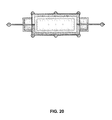
FIGS. 20 and 21 are top and bottom plan views of the lighting device of FIG. 17.
FIG. 22 is a cross-sectional view of the lighting device of FIG. 17.
FIG. 23 is a side-elevation view of a second embodiment of a lighting device according to the invention, in this case the support structure of a ceiling fan-lamp, with partial cutaways to show interior structure.
FIGS. 24-28 are elevation views similar to FIG. 23 showing details of wiring from the master dimming controller to each of the zones.
FIG. 29 is a composite of elevation and plan views of the elements of a third embodiment of a lighting device, in this case a classical-style chandelier, incorporating multiple zones of lighting in a single support structure, with partial cutaways to show interior structure.
FIG. 30 is a wiring diagram for the lighting device of FIG. 29.
FIGS. 31-38 are elevation views of the lighting device of FIG. 29 showing details of wiring from the master dimming controller to each of the zones.
DETAILED DESCRIPTION Definitions
Lighting Scene: A lighting Scene is a group of Lighting Zones wherein each Zone's illumination level is determined by its respective dimmer.
Lighting Zone: A lighting Zone consists of one or more light sources or elements such as an incandescent lamps, halogen lamps or light emitting diodes whose illumination level is commonly controlled by a single dimmer. A lighting zone can also be a motor, as in a ceiling fan, with direction and speed controls.
FIG. 1 exemplifies the prior art of a single dimmer 102 installed in a single gang electrical box controlling a single light fixture 105. This is representative of the most common existing wiring in residential buildings. The single A.C. Hot wire 104 precludes the dimmer from controlling more than one lighting zone. An existing residence wired in this configuration would require substantial and expensive remodeling of the existing wiring enclosed within the wall and ceiling spaces.
FIG. 2 exemplifies the prior art of multiple wall mounted dimmers controlling multiple lighting zones. This is representative of common existing wiring in residential buildings for multiple dimmers. In this configuration, existing residences are precluding from changing the location of or adding additional lighting zones without extensive remodeling.
FIG. 3 exemplifies the dimming control improvements over the prior art wiring limitations shown in FIG. 1 and FIG. 2.
In this exemplary illustration of system 301, a Master Dimmer Controller 310 is mounted within the physical support structure of a lighting device 311. Electrical power for the lighting device 311 is provided by a single A.C. circuit consisting of a A.C. Hot wire 303, A.C. Neutral wire 302 and safety ground wire (not shown). The Master Dimmer Controller 310 allows for a plurality of individually controlled dimmable lighting zones powered by a single A.C. circuit.
A wall mounted or portable keypad or remote control device 312 transmits digital information containing the illumination level for each lighting zone to the Master Dimmer Controller 310 via the Communication Link 304. The Communication Link 304 may be implemented in any of a plurality of wireless media including Radio Frequency (R.F.), Infrared Light (I.R.), Data over Power Line, or a directly wired connection. The remote control device can be a special-purpose device or can be implemented by software in a smart-phone using, e.g., BLUETOOTH® communications.
The Zone Dimmers 308 may support the electrical and dimming requirements of a multitude of lighting technologies such as incandescent lamps, low voltage halogen lamps, or L.E.D. lamps. Each Light Fixture Zone 309 has at least one lamp or other lighting element.
A lighting device with an integrated multiple zone dimming controller enables existing residential or commercial lighting fixtures to be retrofitted with an advanced lighting fixtures capable of providing advanced lighting architecture solutions without modifying the preexisting wiring.
FIG. 4 is an example of a generic lighting device consisting of an integrated Master Dimming Controller 402, six independently dimmable Zone Dimmers 405. In this example, the lighting fixture utilizes three illumination technologies in six zones: Zone 1 three incandescent lamps 401; Zone 2 three low voltage halogen lamps 407; Zone 3 two incandescent lamps; Zone 4 three L.E.D. lamps 409; Zone 5 eight incandescent lamps; Zone 6 four incandescent lamps.
FIG. 5 is a block diagram of a typical wall mounted keypad for use in system 301. The microcontroller 508 detects and processes keypad 504 switch closures and transmits the state of each keypad switch to Master Dimmer Controller 310 via Communications Module 502.
FIG. 6 is an example implementation of the keypad microcontroller circuit. Microcontroller 601, such as a Microchip Technology microprocessor part number PIC18F4321, is programmed by interfacing the Programming Test Points 602 with a compatible programming device such as a Microchip Technology PICKIT3, ICD3 or RealICE. The microcontroller 601 program scans the rows and columns of the keypad button matrix by sequentially setting one of the Key_Col0 through Key Col 3 output pins to a logical ‘1’ (+5V) while the others are set to a logical ‘0’ (0V). Each Key_Row0 through Key_Row 3 input pins are read into a memory location indicating the current state of each of four buttons in the respective column. FIG. 7 depicts the keypad button matrix.
If a Scene button is pressed and held for greater than two seconds, the Mode field shall be toggled from a ‘0’ to a ‘1’ or a ‘1’ to a ‘0’ to indicate the mode is in Programming or Normal mode respectively. The Scene button initiating the Programming mode shall be reported to the Master Dimming Controller in the Keypad Data Payload.
The microcontroller 601 program periodically reports the following Keypad data shown in TABLE 1 below to the Master Dimming Controller:
TABLE 1
Keypad Data Payload
Field Position Type Value Notes
Target Light 0 Bits(3-0) 0x0-0xf Lighting
Fixture ID Default = 0x0 Fixture ID
Mode 0 Bit(7) 0 = Normal
1 = Program
Program
1 UINT8 1-16 Scene Button
Scene number
Number initiating
program mode
Current 1-2 Bit(0) = K1, 0 = Not Pressed
Button Bit(1) = K2, 1 = Pressed
State . . .
Bit(15) = K16
Previous 3-4 Bit(0) = K1, 0 = Not Pressed
Button Bit(1) = K2, 1 = Pressed
State . . .
Bit(15) = K16
FIG. 7 is an example of a common industry practice combining a plurality of switches into a matrix of rows and columns to reduce the total number of I/O pins required to read each switch. In this example, switch contact 701 forms a unique switch (button). Isolation diodes 702 allow the microcontroller to detect multiple simultaneous switch closures. Detecting two or more simultaneous switch closures allows the microcontroller to implement alternative functionality.
FIG. 8 is an implementation of the keypad to use a Master Dimmer Controller communications link using, for example, an industry standard Wi-Fi 802.11b communications module 801, Microchip Technology part number MRFWBOMA. The MRFWBOMA module is controlled by the keypad microcontroller 601 via an industry standard SPI serial data interface port. The module 801 has serial data input port 802 and serial data output port 803.
FIG. 9 is an implementation of the keypad to use a Master Dimmer Controller communications link implemented using Echelon Corporation's Power Line Communications technology, Echelon P/N PL3170. The PL3170 power line module is controlled by the keypad microcontroller 601 via an industry standard SPI serial data I/ O interface port 904, 905.
FIG. 10 is a commonly used power supply implementation. Transformer 1003 reduces the 110 volt A.C. input via lines 1001, 1002 to 10 volts. A.C. Bridge rectifier 1004 and capacitor C11 convert the A.C. voltage to an unregulated, filtered D.C. voltage. The linear voltage regulator 1005 converts the unregulated D.C. voltage to a fixed +5 volt output to power the remaining keypad components.
FIG. 11 is a block diagram of a Master Dimming Controller. This exemplary implementation uses a Microchip Technology PIC18F2321 microcontroller 1101. The microcontroller 1101 receives the keypad switch state data via the Communications Module 1105. The serial data interface 1106 is an industry standard SPI serial data interface.
Up to 16 Master Dimming Controller lighting fixtures can be controlled with a single Keypad. In a multiple Master Dimming Controller lighting fixture environment, each lighting fixture's ID “DIP” switch 1108 is set to a unique four binary bit combination. The default setting for the “DIP” switch is 0000.
The microcontroller 1101 has internal non-volatile EEPROM memory which stores the illumination level for each of the dimming zones 1107. In the event of a power failure optionally all zones will return to the factory settings.
The Master Dimming Controller microcontroller either polls for or is interrupted by the communication module's reception of a Keypad data payload. Upon receipt of the payload, the Master Dimming Controller compares the received “Target Light Fixture ID” to the value of the DIP Switch 1108. If the values match, the Master Dimming Controller parses the remainder of the received data payload.
The bitwise comparison of exclusive OR'ing (XOR) of the Current Button State and Last Button State to the respective Current Button State determines whether the Current Button State is the result of a make, break or steady state condition of a specific button as shown in TABLE 2:
TABLE 2
Current Button State Bit (Kx) Bitwise XOR Bit (Kx) Notes
0 0 Released
0 1 Break
1 0 Pressed
1 1 Make

Scene Selection
If the Keypad Data Payload bit field “Mode” is set to zero and a Scene Keypad button indicates a “Make” condition, the Controller retrieves the respective Scene's Zone illumination from the non-volatile and sets all zone illumination levels respectively. If more than one Scene Button is determined to be in the “Make” condition, the remaining Scene Buttons are ignored.
Scene Programming
If the Keypad Data Payload bit field “Mode” is set to ‘1’, programming mode is enabled. The keypad switches K1-K5 are remapped to different functions as shown in TABLE 3 below.
1. The Keypad Data Payload field “Program Scene Number” specifies which of 16 possible scenes is to be programmed based upon the last Scene button pressed for greater than two seconds.
2. Target Lighting Fixture Selection: The Scene 1 buttons is now remapped and causes the Keypad to rotate through each of the 16 valid Target Lighting Fixture ID values each time the button is pressed. Each time the button is pressed, the corresponding lighting fixture will flash all of its lamps for a period of about one second.
3. Zone Selection: The Scene 2 button is now remapped and causes the Controller to rotate through each of the valid Zones each time the button is pressed. During programming, only the selected zone lamps will be illuminated.
4. Zone Illumination Level: The Scene 3 and Scene 4 buttons are now remapped to increase or decrease the lighting level for the selected zone with each respective button press. Upon release of a button press, the then current zone illumination level will be stored in the respective Scene and Zone non-volatile microcontroller memory location.
5. Additional lighting zones may be programmed as shown in steps 3 and 4 above.
6. Additional Target Lighting Fixtures may be programmed as shown in steps 2, 3, and 4 above.
7. Programming Exit: Press and hold any Scene button for greater than two seconds.
TABLE 3
Keypad Button Function Mapping
Programming
Button Normal Mode Mode Notes
K1 Scene
1 Select Target Press to increment ID #;
Lighting All zones on targeted ID
Fixture ID will flash for one second
K2 Scene
2 Zone Select Press to select Zone;
only selected zone will
be illuminated.
K3 Scene 3 Zone Brighter
K4 Scene
4 Zone Dimmer
K5-K16 Scene 5-Scene 16 N/A
FIG. 12 depicts industry standard dimming control of A.C. line voltages. Each dimming zone is controlled by a semiconductor device known in the industry as a triac. When the triac control signal 1201 is set by the microcontroller to zero volts, the optically isolated triac driver 1202 triggers the gate of the triac 1203, turning the triac switch on. A triac inherently turns off upon the next occurring zero crossing of the A.C. voltage cycle if the triac gate is not triggered.
Dimming of a lamp is accomplished when a pulse is applied to the triac's gate at some time after a zero crossing of the A.C. signal. If the triac pulse is shorter that the total time of the A.C. half cycle period, the triac will inherently turn off. Thus, the triac is only on for a portion of a half cycle of the A.C. line voltage. The reduction in total power applied to a lamp results in a lower light output. The use of triacs for dimming is compatible with all incandescent lamps and newer generation compact florescent lamps/L.E.D sources. In this example, the microcontroller generates a triac trigger control pulse signal 1201 N microseconds after the Zero_Cross_Detect interrupt. The Full illumination is achieved when the dimming delay=1. Illumination decreases proportionally as the delay increases. A dimming delay=0 is reserved to indicate the zone is Off.
Ceiling fan motor speed and direction control is implemented by repurposing two dimming zones. In an implementation, one dimming zone is designated as the Fan Speed Zone. A second dimming zone is designated as the Fan Direction Zone.
A lamp dimming zone is repurposed as a Fan Direction A.C. switch by setting the triac control signal 1201 to a steady state of either ‘1’ or ‘0’. When the triac control signal is a ‘1’, the zone output 1204 is OFF; When the triac control signal 1201 is a ‘0’, the zone triac 1204 ON. The Fan Direction Zone control power to the coil of single pole double throw (S.P.D.T.) relay (not shown). The relay's Common contact is connected to the Fan Speed Zone. The relay's Normally Open and Normally Closed contacts are connected to the ceiling fan motor's forward and reverse direction windings. If the Fan Direction Zone is ON, the ceiling fan rotates in the one direction. If the Fan Direction Zone is OFF, the ceiling fan rotates in the opposite direction.
The Fan Speed Zone controls the ceiling fan motor speed in the same manner as dimming a lamp, i.e. the triac is turned on only during a portion of the A.C. cycle, reducing the average power applied to the motor. As the average power decreases, the motor speed decreases. The Zero Cross Detection Circuit in FIG. 13 generates a pulse 1302 every half cycle when the rectified A.C. voltage 1301 is above zero volts. Upon the rising edge of the Zero_Cross_Detect pulse, an interrupt is generated within the microcontroller indicating the beginning of each dimming control cycle.
FIG. 14 is an implementation of the Master Dimmer Controller to use a Keypad communications link implemented using Echelon Corporation's Power Line Communications technology, Echelon P/N PL3170. The PL3170 module is coupled to the A.C. power line via an A.C. coupling circuit 1401 and is controlled by the keypad microcontroller via an industry standard SPI serial data I/ O interface port 1402, 1403.
FIG. 15 is an implementation of the Master Dimmer Controller to use a Keypad communications link using an industry standard Wi-Fi 802.11b communications module 1501, Microchip Technology part number MRFWBOMA. The MRFWBOMA module is controlled by the keypad microcontroller 601 via an industry standard SPI serial data I/O interface port 1502.
FIG. 16 is a commonly used power supply implementation that can be used in the disclosed lighting device. Transformer 1603 reduces the 110 volt A.C. input via lines 1601, 1602 to 10 volts. A.C. Bridge rectifier 1604 and capacitor C11 convert the A.C. voltage to an unregulated D.C. voltage. The linear voltage regulator 1605 converts the unregulated D.C. voltage to a fixed +5 volt output to power the remaining keypad components. A zero-crossing input signal 1605 is output from the rectifier for use as signal 1301 in FIG. 13. In each embodiment of the lighting device there are lighting zones. These zones can be included in any combination to create a plurality of scenes, preferably four to six scenes. For example, in a dining room application, it is common for the house wiring to allow for only one chandelier in the room, providing general lighting. When operated at full brightness, this chandelier causes an excessive amount of glare. It would be desirable to pre-set the general lighting function of the chandelier at less than full brightness to reduce glare while also providing accent lighting, indirect lighting and/or task lighting from the same chandelier. Each remote controller has numerous scene buttons. By selecting a specific scene on one of the remote controllers, one or more zones are dimmed or one or more zones are raised in light intensity and one or more zones are turned on or off, one or more zones are dimmed or turned off while other zones increased in light intensity. Each of the scenes and fade rates of each of the scenes is pre-programmed at the factory but can be re-programmed via the remote controller.
Another desired option is a display mode, in which the scenes cycle, staying a pre-determined time such as 15 seconds at each scene and then fading to the next scene. Another option would be a security mode which could be programmed to come on at certain times of the night or a pre-selected scene would come on 30 seconds after outside motion lights or sensors were activated. This would only happen in the away mode.
Following are three examples of lighting devices implementing the present invention.
Example 1
FIGS. 17-22 show a modern-style chandelier incorporating six zones of lighting fixtures. Each of these zones is connected to and controlled by a master dimming controller, as previously described, mounted in the ceiling base. Zone 6 Task lighting is powered from the controller through A.C. power lines extending through the base and the oppositely extending arms to the fixtures. Zones 1 through 5 are powered by separate lines extending from the master dimming controller in the base through tubes that suspend the main body of the chandelier from the base. The main body of the chandelier in this example has upper and lower cross beams interconnected by a web. Zones 1 and 2 are downwardly directed lamps, which may be aimable, to provide accent lighting and task lighting. Zone 3 has six upward-directed lamps to provide general area lighting. The upper bar includes ten Zone 4 lamps, best seen in FIG. 22, that are downward directed and spaced close to the web to providing grazing lighting on the face of the web which may be grooved to create artistic light effects. The upper bar also includes Zone 5 lamps, best seen in FIG. 21 that are upward directed to illuminate the surrounding ceiling and thereby provide indirect lighting.
Example 2
FIGS. 23-28 show a ceiling fan lamp incorporating five zones: four zones of lighting fixtures (Zones 1-4) plus one zone (Zone 5) for the fan motor. Zones 1, 2 and 3 utilize low voltage lighting fixtures, which can be LEDs or high intensity lamps to provide different illumination effects, and are controlled by low voltage outputs from the master dimming control. Zone 4 is a high voltage zone to provide general illumination from an incandescent lamps. Zone 5 is the fan motor circuit, for which the master dimming controller can provide speed and direction controlled power signals.
Example 3
FIGS. 29-39 show another example of a chandelier with a master control dimming system. In this particular embodiment of my invention, the dimming system is in the base or canopy of the light fixture mounted to the fire-plate. In this embodiment, the chandelier uses the Echelon power line Smart Transceivers to communicate between the chandelier and a remote control dimmer, mounted in a wall box. A wireless handheld remote can also communicate with the master dimming control mounted within the canopy. (It is understood that other companies in addition to Echelon offer power line technology.)
In FIG. 29, this chandelier has 8 different zones. Each zone performs a different lighting effect such as in zone 1 general area lighting; in zone 2 indirect lighting near the top of the body of the chandelier; in zone 3 indirect lighting behind the decorative badges around the center decorative ring; in zone 4 task lighting; in zone 5 accent lighting under the chandelier's decorative ring; in zone 6 indirect lighting around and on the bottom side of the canopy; in zone 7 task lights on the upper arms extend in opposite directions from the canopy beyond the diameter of the body of the chandelier; and in zone 8 indirect lighting within the canopy.
The lights on the ends of the ceiling canopy arms (Zone 7) extend beyond the diameter of the chandelier so that their light beams are not blocked by the chandelier.
FIG. 30 is a schematic of wiring from the master dimming control to the various zones. One hot wire from the master dimming control to each of the high voltage zones in the chandelier (Zones 1 and 4) plus one neutral wire and a ground wire are laced through the chain and fed through the screw collar loop and pipe nipple. The wires pass out of the pipe nipple in the electrical box and are connected to the master dimming control. One hot wire from each of the high voltage zones in the ceiling canopy (Zone 7) plus one neutral wire and a ground wire are also connected to the master dimming control. Wire connections could be completed with wire nuts or a quick-connect device. Each of the low voltage zones ( Zones 2, 3, 5, 6 and 8) are connected to the low voltage terminals of the master dimming control via DC wire pairs.
A single AC power supply wire comes into the master dimming control in the canopy and power is distributed to the various zones from there. FIG. 31 shows exemplary high voltage wiring from the Zone 1 output of the master dimming control to the six lighting fixtures of Zone 1. Similar high voltage connections are shown in FIGS. 34 and 37 for Zones 4 and 7. FIG. 32 shows exemplary low voltage wiring from the master dimming control to the four low voltage lighting fixtures of Zone 2. Similar low voltage connections are shown in FIGS. 33, 35, 36 and 38 for Zones 3, 5, 6 and 8.
Having described and illustrated the principles of the invention in various embodiments thereof, it should be apparent that the invention can be modified in arrangement and detail without departing from such principles. I claim all modifications and variations coming within the spirit and scope of the following claims.

Claims (24)

The invention claimed is:
1. A multi-scene, multi-zone lighting device comprising:
a support structure of a lighting device supporting multiple lighting zones, each lighting zone including one or more lighting sources, one or more of the multiple zones defining a lighting scene;
a master dimming control built into the support structure, the master dimming control having a power input line and multiple dimmers, each dimmer having an output line, and each of the zones coupled to one of the dimmer output lines to receive a controlled setting from the corresponding dimmer;
a remote control device including a communications module in communications with the master dimming control, a memory for storing N sets of settings for the multiple zones, and a user interface for a user to select a stored setting for each zone,
the master dimming control including a communications receiver and a controller responsive to receiving the set of settings to set the controlled setting of the corresponding dimmer for each zone in the selected scene and thereby conform the zones to the set of settings in the selected scene.
2. A multi-scene, multi-zone lighting device according to claim 1 in which the remote control device communicates with the master dimming control via wireless communications.
3. A multi-scene, multi-zone lighting device according to claim 1 in which the remote control device communicates with the master dimming control via power-line communications.
4. A multi-scene, multi-zone lighting device according to claim 1 in which the user interface is operative to enable the user to input a setting for each zone into the remote control device and further operative to enable the user to store each set of settings as a scene so that the user can apply a stored set of settings by selecting a corresponding scene.
5. A multi-scene, multi-zone lighting device according to claim 1 in which the memory for storing N sets of settings includes preset settings for the multiple zones.
6. A multi-scene, multi-zone lighting device according to claim 1 in which the memory for storing N sets of settings includes default settings for the multiple zones.
7. A multi-scene, multi-zone lighting device according to claim 1 in which the master dimming control includes dimmers for at least four zones and the memory for storing N sets of settings provides for storage of at least four settings in each set and the number of N sets is at least two for storing settings for at least two scenes.
8. A multi-scene, multi-zone lighting device comprising:
a support structure of a lighting device supporting multiple lighting zones, each lighting zone including one or more lighting sources, one or more of the multiple zones defining a lighting scene;
a master dimming control built into the support structure, the master dimming control having a power input line and multiple dimmers, each dimmer having an output line, and each of the zones coupled to one of the dimmer output lines to receive a controlled setting from the corresponding dimmer; and
a remote control device including a communications module in communications with the master dimming control, a memory for storing N sets of settings for the multiple zones, and a user interface for a user to select a stored setting for each zone,
the master dimming control including a communications receiver and a controller responsive to receiving the set of settings to set the controlled setting of the corresponding dimmer for each zone in the selected scene and thereby conform the zones to the set of settings in the selected scene;
in which a single power line provides power to the master dimming controller which in turn distributes power according the settings in the selected scene to the zones.
9. A multi-scene, multi-zone lighting device according to claim 8 in which at least one of the dimmers is operative to distribute high voltage power to one of the zones.
10. A multi-scene, multi-zone lighting device according to claim 8 in which at least one of the dimmers is operative to distribute low voltage power to one of the zones.
11. A multi-scene, multi-zone lighting device comprising:
a support structure of a lighting device supporting multiple lighting zones, each lighting zone including one or more lighting sources, the multiple zones together defining a lighting scene;
a master dimming control built into the support structure, the master dimming control having a power input line and multiple dimmers, each dimmer having an output line, and each of the zones coupled to one of the dimmer output lines to receive a controlled setting from the corresponding dimmer;
a remote control device including a communications module in communications with the master dimming control, a memory for storing N sets of settings for the multiple zones, each set of settings defining the settings for a scene, and a user interface for a user to select and transmit a stored set of settings for a desired scene to the master dimming control;
the master dimming control including a controller responsive to receiving the set of settings to set the corresponding dimmers for the selected scene.
12. A multi-scene, multi-zone lighting device according to claim 11 in which the multiple zones include light sources on the support structure for at least three of the following zones: a general area lighting zone, a downward direct or task lighting zone, an accent lighting zone, an indirect lighting zone, and a grazing lighting zone.
13. A multi-scene, multi-zone lighting device according to claim 11 in which one of the multiple zones further include a fan motor, and the master dimming control includes a dimmer for controlling motor speed and circuitry for controlling motor direction.
14. A multi-scene, multi-zone lighting device according to claim 11 in which one or more of the multiple zones includes a color changeable light source.
15. A multi-scene, multi-zone lighting device according to claim 11 in which the multiple zones include light sources on the support structure for the following zones: a general area lighting zone, a downward direct or task lighting zone, and an accent lighting zone.
16. A multi-scene, multi-zone lighting device according to claim 11 in which the multiple zones include light sources on the support structure for the following zones: a general area lighting zone, a downward direct or task lighting zone, and an indirect lighting zone.
17. A multi-scene, multi-zone lighting device according to claim 11 in which the multiple zones include light sources on the support structure for the following zones: a general area lighting zone, a downward direct or task lighting zone, and a grazing lighting zone.
18. A multi-scene, multi-zone lighting device according to claim 11 in which the multiple zones include light sources on the support structure for the following zones: an accent lighting zone, a downward direct or task lighting zone, and a grazing lighting zone.
19. A multi-scene, multi-zone lighting device according to claim 11 in which the multiple zones include light sources on the support structure for the following zones: an indirect lighting zone, a downward direct or task lighting zone, and a grazing lighting zone.
20. A multi-scene, multi-zone lighting device according to claim 19 in which one or more of the multiple zones includes a color changeable light source.
21. A multi-scene, multi-zone lighting device comprising:
a support structure of a lighting device supporting multiple lighting zones, each lighting zone including one or more lighting sources, one or more of the multiple zones defining a lighting scene;
a master dimming control built into the support structure, the master dimming control having a power input line and multiple dimmers, each dimmer having an output line, and each of the zones coupled to one of the dimmer output lines to receive a controlled setting from the corresponding dimmer; and
a remote control device including a communications module in communications with the master dimming control, a memory for storing N sets of settings for the multiple zones, and a user interface for a user to select a stored setting for each zone,
the master dimming control including a communications receiver and a controller responsive to receiving the set of settings to set the controlled setting of the corresponding dimmer for each zone in the selected scene and thereby conform the zones to the set of settings in the selected scene;
in which the support structure includes an upper portion and a lower portion suspended from the upper portion, the lower portion supporting light sources for multiple zones and having a first diameter, and the upper portion having a second diameter at which one or more light sources for at least one additional zone are supported, the second diameter being greater than the first diameter.
22. A multi-scene, multi-zone lighting device according to claim 21 in which the multiple zones include light sources on the support structure for at least three of the following zones: a general area lighting zone, a downward direct or task lighting zone, an accent lighting zone, an indirect lighting zone, and a grazing lighting zone.
23. A multi-scene, multi-zone lighting device comprising:
a support structure of a lighting device supporting multiple lighting zones, each lighting zone including one or more lighting sources, one or more of the multiple zones defining a lighting scene;
a master dimming control built into the support structure, the master dimming control having a power input line and multiple dimmers, each dimmer having an output line, and each of the zones coupled to one of the dimmer output lines to receive a controlled setting from the corresponding dimmer; and
a remote control device including a communications module in communications with the master dimming control, a memory for storing N sets of settings for the multiple zones, and a user interface for a user to select a stored setting for each zone,
the master dimming control including a communications receiver and a controller responsive to receiving the set of settings to set the controlled setting of the corresponding dimmer for each zone in the selected scene and thereby conform the zones to the set of settings in the selected scene;
in which the support structure includes a base portion and a body portion connected to the base portion, the body portion supporting light sources for multiple zones, and the base portion having one or more light sources for at least one additional zone.
24. A multi-scene, multi-zone lighting device according to claim 23 in which the lighting device includes a floor lamp.
US13/762,186 2012-02-07 2013-02-07 Combined lighting device with an integrated dimming control system Active 2033-07-01 US9035572B1 (en)

Priority Applications (6)

Application Number Priority Date Filing Date Title
US13/762,186 US9035572B1 (en) 2012-02-07 2013-02-07 Combined lighting device with an integrated dimming control system
US14/695,464 US9538622B1 (en) 2012-02-07 2015-04-24 Combined lighting device with an integrated dimming control system
US15/392,216 US9907149B1 (en) 2012-02-07 2016-12-28 Combined lighting device with an integrated dimming control system
US15/870,515 US10278269B2 (en) 2012-02-07 2018-01-12 Combined lighting device with an integrated dimming control system
US16/172,000 US10813199B2 (en) 2012-02-07 2018-10-26 Combined lighting device with an integrated dimming control system
US17/074,266 US11466828B2 (en) 2012-02-07 2020-10-19 Combined lighting device with an integrated dimming control system

Applications Claiming Priority (2)

Application Number Priority Date Filing Date Title
US201261596101P 2012-02-07 2012-02-07
US13/762,186 US9035572B1 (en) 2012-02-07 2013-02-07 Combined lighting device with an integrated dimming control system

Related Child Applications (1)

Application Number Title Priority Date Filing Date
US14/695,464 Continuation US9538622B1 (en) 2012-02-07 2015-04-24 Combined lighting device with an integrated dimming control system

Publications (1)

Publication Number Publication Date
US9035572B1 true US9035572B1 (en) 2015-05-19

Family

ID=53054630

Family Applications (2)

Application Number Title Priority Date Filing Date
US13/762,186 Active 2033-07-01 US9035572B1 (en) 2012-02-07 2013-02-07 Combined lighting device with an integrated dimming control system
US14/695,464 Active 2033-08-12 US9538622B1 (en) 2012-02-07 2015-04-24 Combined lighting device with an integrated dimming control system

Family Applications After (1)

Application Number Title Priority Date Filing Date
US14/695,464 Active 2033-08-12 US9538622B1 (en) 2012-02-07 2015-04-24 Combined lighting device with an integrated dimming control system

Country Status (1)

Country Link
US (2) US9035572B1 (en)

Cited By (25)

* Cited by examiner, † Cited by third party
Publication number Priority date Publication date Assignee Title
CN106230428A (en) * 2016-08-31 2016-12-14 浙江宙辉电器有限公司 A kind of infrared induction circuit
US9538622B1 (en) * 2012-02-07 2017-01-03 Dolan Designs Incorporated Combined lighting device with an integrated dimming control system
USD803474S1 (en) * 2016-04-07 2017-11-21 Robert A. Sonneman Canopy for light fixtures
WO2018009699A1 (en) * 2016-07-07 2018-01-11 Pennycooke Nicholas David Intelligent lighting control system air gap apparatuses, systems, and methods
WO2018009775A3 (en) * 2016-07-08 2018-02-08 Cheung Ann Claire Lim Chi Intelligent lighting control system automated adjustment apparatuses, systems, and methods
US9907149B1 (en) * 2012-02-07 2018-02-27 Dolan Designs Incorporated Combined lighting device with an integrated dimming control system
EP3322259A1 (en) * 2016-11-09 2018-05-16 Niko NV Double dimmer antenna configuration
US20190098734A1 (en) * 2012-02-07 2019-03-28 Dolan Designs Incorporated Combined lighting device with an integrated dimming control system
US10292247B2 (en) * 2015-10-16 2019-05-14 Delight Innovative Technologies Limited Intelligent installation method of indoor lighting system
US10418813B1 (en) 2017-04-01 2019-09-17 Smart Power Partners LLC Modular power adapters and methods of implementing modular power adapters
US10727731B1 (en) 2017-04-01 2020-07-28 Smart Power Partners, LLC Power adapters adapted to receive a module and methods of implementing power adapters with modules
US10917956B1 (en) 2019-06-30 2021-02-09 Smart Power Partners LLC Control attachment configured to provide power to a load and method of configuring a control attachment
US10938168B2 (en) 2019-06-30 2021-03-02 Smart Power Partners LLC In-wall power adapter and method of controlling the application of power to a load
US10958026B1 (en) 2019-06-30 2021-03-23 Smart Power Partners LLC Contactless thermometer for an in-wall power adapter
US10958020B1 (en) 2019-06-30 2021-03-23 Smart Power Partners LLC Control attachment for an in-wall power adapter and method of controlling an in-wall power adapter
US10965068B1 (en) 2019-06-30 2021-03-30 Smart Power Partners LLC In-wall power adapter having an outlet and method of controlling an in-wall power adapter
US10996645B1 (en) 2017-04-01 2021-05-04 Smart Power Partners LLC Modular power adapters and methods of implementing modular power adapters
US11043768B1 (en) 2019-06-30 2021-06-22 Smart Power Partners LLC Power adapter configured to provide power to a load and method of implementing a power adapter
US11189948B1 (en) 2019-06-30 2021-11-30 Smart Power Partners LLC Power adapter and method of implementing a power adapter to provide power to a load
US11201444B1 (en) 2019-06-30 2021-12-14 Smart Power Partners LLC Power adapter having contact elements in a recess and method of controlling a power adapter
US11219108B1 (en) 2019-06-30 2022-01-04 Smart Power Partners LLC Power adapter arrangement and method of implementing a power adapter arrangement
US11231730B1 (en) 2019-06-30 2022-01-25 Smart Power Power LLC Control attachment for a power adapter configured to control power applied to a load
US11264769B1 (en) 2019-06-30 2022-03-01 Smart Power Partners LLC Power adapter having contact elements in a recess and method of controlling a power adapter
US11460874B1 (en) 2019-06-30 2022-10-04 Smart Power Partners LLC In-wall power adapter configured to control the application of power to a load
US11579640B1 (en) 2019-06-30 2023-02-14 Smart Power Partners LLC Control attachment for an in-wall power adapter

Citations (20)

* Cited by examiner, † Cited by third party
Publication number Priority date Publication date Assignee Title
US4719446A (en) 1984-05-07 1988-01-12 Casablanca Fan Company, Inc. Remote control for combined ceiling fan and light fixture
US4918690A (en) 1987-11-10 1990-04-17 Echelon Systems Corp. Network and intelligent cell for providing sensing, bidirectional communications and control
US5059871A (en) 1990-07-09 1991-10-22 Lightolier Incorporated Programmable lighting control system linked by a local area network
US5191265A (en) 1991-08-09 1993-03-02 Lutron Electronics Co., Inc. Wall mounted programmable modular control system
US5736965A (en) 1996-02-07 1998-04-07 Lutron Electronics Co. Inc. Compact radio frequency transmitting and receiving antenna and control device employing same
US5838226A (en) 1996-02-07 1998-11-17 Lutron Electronics Co.Inc. Communication protocol for transmission system for controlling and determining the status of electrical devices from remote locations
US5848054A (en) 1996-02-07 1998-12-08 Lutron Electronics Co. Inc. Repeater for transmission system for controlling and determining the status of electrical devices from remote locations
US5905442A (en) 1996-02-07 1999-05-18 Lutron Electronics Co., Inc. Method and apparatus for controlling and determining the status of electrical devices from remote locations
US5909087A (en) 1996-03-13 1999-06-01 Lutron Electronics Co. Inc. Lighting control with wireless remote control and programmability
US6046550A (en) * 1998-06-22 2000-04-04 Lutron Electronics Co., Inc. Multi-zone lighting control system
US20060076908A1 (en) * 2004-09-10 2006-04-13 Color Kinetics Incorporated Lighting zone control methods and apparatus
US20060202851A1 (en) * 2005-03-12 2006-09-14 Cash Audwin W Handheld programmer for lighting control system
US7227341B2 (en) 2005-01-18 2007-06-05 Echelon Corporation Circuit for use with switched leg power supply
US7345998B2 (en) 2004-12-15 2008-03-18 Smart Labs, Inc. Mesh network of intelligent devices communicating via powerline and radio frequency
US20090218951A1 (en) * 2008-03-02 2009-09-03 Mpj Lighting, Llc Lighting and control systems and methods
US20090230894A1 (en) * 2006-05-11 2009-09-17 Koninklijke Philips Electronics N.V. Lighting system with linked groups
US20090284966A1 (en) * 2008-05-16 2009-11-19 Musco Corporation Lighting system with combined directly viewable luminous or transmissive surface and controlled area illumination
US20100277106A1 (en) * 2007-12-20 2010-11-04 Koninklijke Philips Electronics N.V. Scene setting control for two light groups
US20110140832A1 (en) * 2008-08-13 2011-06-16 Koninklijke Philips Electronics N.V. Updating scenes in remote controllers of a home control system
US8467887B2 (en) * 2009-11-09 2013-06-18 Samsung Electronics Co., Ltd. System for controlling lighting devices

Family Cites Families (2)

* Cited by examiner, † Cited by third party
Publication number Priority date Publication date Assignee Title
US5967640A (en) * 1994-12-16 1999-10-19 Moriyama Sangyo Kabushiki Kaisha Equipment using mounting hole of ceiling as fixing element and accessory devices
US9035572B1 (en) * 2012-02-07 2015-05-19 Dolan Designs Incorporated Combined lighting device with an integrated dimming control system

Patent Citations (21)

* Cited by examiner, † Cited by third party
Publication number Priority date Publication date Assignee Title
US4719446A (en) 1984-05-07 1988-01-12 Casablanca Fan Company, Inc. Remote control for combined ceiling fan and light fixture
US4918690A (en) 1987-11-10 1990-04-17 Echelon Systems Corp. Network and intelligent cell for providing sensing, bidirectional communications and control
US5844888A (en) 1987-11-10 1998-12-01 Echelon Corporation Network and intelligent cell for providing sensing, bidirectional communications and control
US5059871A (en) 1990-07-09 1991-10-22 Lightolier Incorporated Programmable lighting control system linked by a local area network
US5191265A (en) 1991-08-09 1993-03-02 Lutron Electronics Co., Inc. Wall mounted programmable modular control system
US5736965A (en) 1996-02-07 1998-04-07 Lutron Electronics Co. Inc. Compact radio frequency transmitting and receiving antenna and control device employing same
US5838226A (en) 1996-02-07 1998-11-17 Lutron Electronics Co.Inc. Communication protocol for transmission system for controlling and determining the status of electrical devices from remote locations
US5848054A (en) 1996-02-07 1998-12-08 Lutron Electronics Co. Inc. Repeater for transmission system for controlling and determining the status of electrical devices from remote locations
US5905442A (en) 1996-02-07 1999-05-18 Lutron Electronics Co., Inc. Method and apparatus for controlling and determining the status of electrical devices from remote locations
US5909087A (en) 1996-03-13 1999-06-01 Lutron Electronics Co. Inc. Lighting control with wireless remote control and programmability
US6046550A (en) * 1998-06-22 2000-04-04 Lutron Electronics Co., Inc. Multi-zone lighting control system
US20060076908A1 (en) * 2004-09-10 2006-04-13 Color Kinetics Incorporated Lighting zone control methods and apparatus
US7345998B2 (en) 2004-12-15 2008-03-18 Smart Labs, Inc. Mesh network of intelligent devices communicating via powerline and radio frequency
US7227341B2 (en) 2005-01-18 2007-06-05 Echelon Corporation Circuit for use with switched leg power supply
US20060202851A1 (en) * 2005-03-12 2006-09-14 Cash Audwin W Handheld programmer for lighting control system
US20090230894A1 (en) * 2006-05-11 2009-09-17 Koninklijke Philips Electronics N.V. Lighting system with linked groups
US20100277106A1 (en) * 2007-12-20 2010-11-04 Koninklijke Philips Electronics N.V. Scene setting control for two light groups
US20090218951A1 (en) * 2008-03-02 2009-09-03 Mpj Lighting, Llc Lighting and control systems and methods
US20090284966A1 (en) * 2008-05-16 2009-11-19 Musco Corporation Lighting system with combined directly viewable luminous or transmissive surface and controlled area illumination
US20110140832A1 (en) * 2008-08-13 2011-06-16 Koninklijke Philips Electronics N.V. Updating scenes in remote controllers of a home control system
US8467887B2 (en) * 2009-11-09 2013-06-18 Samsung Electronics Co., Ltd. System for controlling lighting devices

Non-Patent Citations (1)

* Cited by examiner, † Cited by third party
Title
Amazon.com, Casablanca Inteli Touch III Handheld Remote control, First available Nov. 1, 2010. *

Cited By (40)

* Cited by examiner, † Cited by third party
Publication number Priority date Publication date Assignee Title
US9538622B1 (en) * 2012-02-07 2017-01-03 Dolan Designs Incorporated Combined lighting device with an integrated dimming control system
US10813199B2 (en) * 2012-02-07 2020-10-20 Dolan Designs Incorporated Combined lighting device with an integrated dimming control system
US9907149B1 (en) * 2012-02-07 2018-02-27 Dolan Designs Incorporated Combined lighting device with an integrated dimming control system
US11466828B2 (en) * 2012-02-07 2022-10-11 Dolan Designs Incorporated Combined lighting device with an integrated dimming control system
US20190098734A1 (en) * 2012-02-07 2019-03-28 Dolan Designs Incorporated Combined lighting device with an integrated dimming control system
US10278269B2 (en) * 2012-02-07 2019-04-30 Dolan Designs Incorporated Combined lighting device with an integrated dimming control system
US10292247B2 (en) * 2015-10-16 2019-05-14 Delight Innovative Technologies Limited Intelligent installation method of indoor lighting system
USD803474S1 (en) * 2016-04-07 2017-11-21 Robert A. Sonneman Canopy for light fixtures
WO2018009699A1 (en) * 2016-07-07 2018-01-11 Pennycooke Nicholas David Intelligent lighting control system air gap apparatuses, systems, and methods
US10524332B2 (en) 2016-07-07 2019-12-31 Noon Home, Inc. Intelligent lighting control system air gap apparatuses, systems, and methods
US11071188B2 (en) 2016-07-07 2021-07-20 Racepoint Energy, LLC Intelligent lighting control system air gap apparatuses, systems, and methods
WO2018009775A3 (en) * 2016-07-08 2018-02-08 Cheung Ann Claire Lim Chi Intelligent lighting control system automated adjustment apparatuses, systems, and methods
US10143069B2 (en) 2016-07-08 2018-11-27 Noon Home, Inc. Intelligent lighting control system automated adjustment apparatuses, systems, and methods
CN106230428A (en) * 2016-08-31 2016-12-14 浙江宙辉电器有限公司 A kind of infrared induction circuit
BE1024728B1 (en) * 2016-11-09 2018-06-12 Niko Nv Double dimmer antenna configuration
EP3322259A1 (en) * 2016-11-09 2018-05-16 Niko NV Double dimmer antenna configuration
US10418813B1 (en) 2017-04-01 2019-09-17 Smart Power Partners LLC Modular power adapters and methods of implementing modular power adapters
US11611233B1 (en) 2017-04-01 2023-03-21 Smart Power Partners LLC Power adapter configured to apply power to a device
US11502461B1 (en) 2017-04-01 2022-11-15 Smart Power Partners LLC In-wall power adapters and methods of implementing in-wall power adapters
US10727731B1 (en) 2017-04-01 2020-07-28 Smart Power Partners, LLC Power adapters adapted to receive a module and methods of implementing power adapters with modules
US10530597B1 (en) 2017-04-01 2020-01-07 Smart Power Partners LLC System for controlling a plurality of power switches configured to apply power to devices
US11101655B2 (en) 2017-04-01 2021-08-24 Smart Power Partners LLC Plug-in power adapters and methods of implementing a plug-in power adapter
US10996645B1 (en) 2017-04-01 2021-05-04 Smart Power Partners LLC Modular power adapters and methods of implementing modular power adapters
US11050254B2 (en) 2017-04-01 2021-06-29 Smart Power Partners LLC Power adapters adapted to receive a module and methods of implementing power adapters with modules
US11050340B2 (en) 2017-04-01 2021-06-29 Smart Power Partners LLC Plug-in power adapters and methods of implementing a plug-in power adapter
US10958020B1 (en) 2019-06-30 2021-03-23 Smart Power Partners LLC Control attachment for an in-wall power adapter and method of controlling an in-wall power adapter
US11043768B1 (en) 2019-06-30 2021-06-22 Smart Power Partners LLC Power adapter configured to provide power to a load and method of implementing a power adapter
US10965068B1 (en) 2019-06-30 2021-03-30 Smart Power Partners LLC In-wall power adapter having an outlet and method of controlling an in-wall power adapter
US11189948B1 (en) 2019-06-30 2021-11-30 Smart Power Partners LLC Power adapter and method of implementing a power adapter to provide power to a load
US11201444B1 (en) 2019-06-30 2021-12-14 Smart Power Partners LLC Power adapter having contact elements in a recess and method of controlling a power adapter
US11219108B1 (en) 2019-06-30 2022-01-04 Smart Power Partners LLC Power adapter arrangement and method of implementing a power adapter arrangement
US11231730B1 (en) 2019-06-30 2022-01-25 Smart Power Power LLC Control attachment for a power adapter configured to control power applied to a load
US11232921B1 (en) 2019-06-30 2022-01-25 Smart Power Partners LLC Power adapter having separate manual and electrical user interfaces
US11264769B1 (en) 2019-06-30 2022-03-01 Smart Power Partners LLC Power adapter having contact elements in a recess and method of controlling a power adapter
US11460874B1 (en) 2019-06-30 2022-10-04 Smart Power Partners LLC In-wall power adapter configured to control the application of power to a load
US10958026B1 (en) 2019-06-30 2021-03-23 Smart Power Partners LLC Contactless thermometer for an in-wall power adapter
US10938168B2 (en) 2019-06-30 2021-03-02 Smart Power Partners LLC In-wall power adapter and method of controlling the application of power to a load
US11579640B1 (en) 2019-06-30 2023-02-14 Smart Power Partners LLC Control attachment for an in-wall power adapter
US11599177B1 (en) 2019-06-30 2023-03-07 Smart Power Partners LLC Power adapter arrangement having a power adapter and a control attachment
US10917956B1 (en) 2019-06-30 2021-02-09 Smart Power Partners LLC Control attachment configured to provide power to a load and method of configuring a control attachment

Also Published As

Publication number Publication date
US9538622B1 (en) 2017-01-03

Similar Documents

Publication Publication Date Title
US9538622B1 (en) Combined lighting device with an integrated dimming control system
US10278269B2 (en) Combined lighting device with an integrated dimming control system
US10813199B2 (en) Combined lighting device with an integrated dimming control system
US11248752B2 (en) Light emitting diode (LED) lighting device or lamp with configurable light qualities
US9913348B2 (en) Light fixtures, systems for controlling light fixtures, and methods of controlling fixtures and methods of controlling lighting control systems
US8288957B2 (en) System for controlling light sources
US9155171B1 (en) Power over ethernet lighting system
CN1943280B (en) Device for lighting a room
US9049756B2 (en) Intelligent lighting control system and network comprising multiple-channel photo sensor
CN107580802B (en) With the control device that illuminates part controlled in response to external sensor
US11751303B2 (en) Configuring color control for lighting devices
JP2009021141A (en) Illumination control device
US9525306B1 (en) Automatic emergency lighting load control
JP7034796B2 (en) Lighting system
TW201436640A (en) Switch system and wall switch used for the same
AU2013204208B2 (en) System and method for programming a controller
WO2024073004A1 (en) System and methods for controlling intensity level and color of lighting devices according to a show
CN203827571U (en) Integrated control system
US20190014640A1 (en) Lighting Control System

Legal Events

Date Code Title Description
AS Assignment

Owner name: DOLAN DESIGNS INCORPORATED, OREGON

Free format text: ASSIGNMENT OF ASSIGNORS INTEREST;ASSIGNOR:DOLAN, PATRICK S.;REEL/FRAME:029776/0888

Effective date: 20130207

STCF Information on status: patent grant

Free format text: PATENTED CASE

MAFP Maintenance fee payment

Free format text: PAYMENT OF MAINTENANCE FEE, 4TH YR, SMALL ENTITY (ORIGINAL EVENT CODE: M2551); ENTITY STATUS OF PATENT OWNER: SMALL ENTITY

Year of fee payment: 4

MAFP Maintenance fee payment

Free format text: PAYMENT OF MAINTENANCE FEE, 8TH YR, SMALL ENTITY (ORIGINAL EVENT CODE: M2552); ENTITY STATUS OF PATENT OWNER: SMALL ENTITY

Year of fee payment: 8