US9196097B2 - Electronic parking meter with vehicle sensor - Google Patents
Electronic parking meter with vehicle sensor Download PDFInfo
- Publication number
- US9196097B2 US9196097B2 US13/468,873 US201213468873A US9196097B2 US 9196097 B2 US9196097 B2 US 9196097B2 US 201213468873 A US201213468873 A US 201213468873A US 9196097 B2 US9196097 B2 US 9196097B2
- Authority
- US
- United States
- Prior art keywords
- meter
- parking
- space
- vehicle
- electronic
- Prior art date
- Legal status (The legal status is an assumption and is not a legal conclusion. Google has not performed a legal analysis and makes no representation as to the accuracy of the status listed.)
- Expired - Fee Related, expires
Links
- 230000007246 mechanism Effects 0.000 claims abstract description 199
- 238000004891 communication Methods 0.000 claims description 168
- 238000000034 method Methods 0.000 claims description 39
- 230000008569 process Effects 0.000 claims description 29
- 238000001514 detection method Methods 0.000 claims description 11
- 238000007726 management method Methods 0.000 description 130
- 238000012545 processing Methods 0.000 description 29
- 230000002093 peripheral effect Effects 0.000 description 20
- 230000006870 function Effects 0.000 description 14
- 238000010586 diagram Methods 0.000 description 13
- 230000008878 coupling Effects 0.000 description 10
- 238000010168 coupling process Methods 0.000 description 10
- 238000005859 coupling reaction Methods 0.000 description 10
- 238000013475 authorization Methods 0.000 description 8
- 239000003795 chemical substances by application Substances 0.000 description 7
- 230000010267 cellular communication Effects 0.000 description 6
- 238000012360 testing method Methods 0.000 description 6
- 230000001965 increasing effect Effects 0.000 description 5
- 238000003860 storage Methods 0.000 description 5
- 230000000694 effects Effects 0.000 description 4
- 230000004048 modification Effects 0.000 description 4
- 238000012986 modification Methods 0.000 description 4
- 230000003287 optical effect Effects 0.000 description 4
- 230000004075 alteration Effects 0.000 description 3
- 230000003247 decreasing effect Effects 0.000 description 3
- 238000013461 design Methods 0.000 description 3
- 238000003780 insertion Methods 0.000 description 3
- 230000037431 insertion Effects 0.000 description 3
- 238000009434 installation Methods 0.000 description 3
- 238000012011 method of payment Methods 0.000 description 3
- 230000008901 benefit Effects 0.000 description 2
- 230000005540 biological transmission Effects 0.000 description 2
- 230000001413 cellular effect Effects 0.000 description 2
- 230000008859 change Effects 0.000 description 2
- 238000013500 data storage Methods 0.000 description 2
- 238000005516 engineering process Methods 0.000 description 2
- 230000001939 inductive effect Effects 0.000 description 2
- 230000004044 response Effects 0.000 description 2
- 239000013589 supplement Substances 0.000 description 2
- 208000032953 Device battery issue Diseases 0.000 description 1
- 239000004593 Epoxy Substances 0.000 description 1
- 230000001133 acceleration Effects 0.000 description 1
- 230000004913 activation Effects 0.000 description 1
- 238000004458 analytical method Methods 0.000 description 1
- 238000012550 audit Methods 0.000 description 1
- 238000004422 calculation algorithm Methods 0.000 description 1
- 239000003086 colorant Substances 0.000 description 1
- 238000010276 construction Methods 0.000 description 1
- 238000004146 energy storage Methods 0.000 description 1
- 238000007689 inspection Methods 0.000 description 1
- 230000001788 irregular Effects 0.000 description 1
- 239000000463 material Substances 0.000 description 1
- 238000005259 measurement Methods 0.000 description 1
- 230000006855 networking Effects 0.000 description 1
- 238000007789 sealing Methods 0.000 description 1
- 238000004513 sizing Methods 0.000 description 1
- 238000006467 substitution reaction Methods 0.000 description 1
- 230000026676 system process Effects 0.000 description 1
- 230000007704 transition Effects 0.000 description 1
Images


Classifications
-
- G—PHYSICS
- G06—COMPUTING; CALCULATING OR COUNTING
- G06Q—INFORMATION AND COMMUNICATION TECHNOLOGY [ICT] SPECIALLY ADAPTED FOR ADMINISTRATIVE, COMMERCIAL, FINANCIAL, MANAGERIAL OR SUPERVISORY PURPOSES; SYSTEMS OR METHODS SPECIALLY ADAPTED FOR ADMINISTRATIVE, COMMERCIAL, FINANCIAL, MANAGERIAL OR SUPERVISORY PURPOSES, NOT OTHERWISE PROVIDED FOR
- G06Q20/00—Payment architectures, schemes or protocols
- G06Q20/08—Payment architectures
- G06Q20/14—Payment architectures specially adapted for billing systems
- G06Q20/145—Payments according to the detected use or quantity
-
- G—PHYSICS
- G06—COMPUTING; CALCULATING OR COUNTING
- G06Q—INFORMATION AND COMMUNICATION TECHNOLOGY [ICT] SPECIALLY ADAPTED FOR ADMINISTRATIVE, COMMERCIAL, FINANCIAL, MANAGERIAL OR SUPERVISORY PURPOSES; SYSTEMS OR METHODS SPECIALLY ADAPTED FOR ADMINISTRATIVE, COMMERCIAL, FINANCIAL, MANAGERIAL OR SUPERVISORY PURPOSES, NOT OTHERWISE PROVIDED FOR
- G06Q30/00—Commerce
- G06Q30/02—Marketing; Price estimation or determination; Fundraising
- G06Q30/0283—Price estimation or determination
- G06Q30/0284—Time or distance, e.g. usage of parking meters or taximeters
-
- G—PHYSICS
- G07—CHECKING-DEVICES
- G07B—TICKET-ISSUING APPARATUS; FARE-REGISTERING APPARATUS; FRANKING APPARATUS
- G07B15/00—Arrangements or apparatus for collecting fares, tolls or entrance fees at one or more control points
-
- G—PHYSICS
- G07—CHECKING-DEVICES
- G07B—TICKET-ISSUING APPARATUS; FARE-REGISTERING APPARATUS; FRANKING APPARATUS
- G07B15/00—Arrangements or apparatus for collecting fares, tolls or entrance fees at one or more control points
- G07B15/02—Arrangements or apparatus for collecting fares, tolls or entrance fees at one or more control points taking into account a variable factor such as distance or time, e.g. for passenger transport, parking systems or car rental systems
-
- G—PHYSICS
- G07—CHECKING-DEVICES
- G07C—TIME OR ATTENDANCE REGISTERS; REGISTERING OR INDICATING THE WORKING OF MACHINES; GENERATING RANDOM NUMBERS; VOTING OR LOTTERY APPARATUS; ARRANGEMENTS, SYSTEMS OR APPARATUS FOR CHECKING NOT PROVIDED FOR ELSEWHERE
- G07C1/00—Registering, indicating or recording the time of events or elapsed time, e.g. time-recorders for work people
- G07C1/30—Parking meters
-
- G—PHYSICS
- G07—CHECKING-DEVICES
- G07C—TIME OR ATTENDANCE REGISTERS; REGISTERING OR INDICATING THE WORKING OF MACHINES; GENERATING RANDOM NUMBERS; VOTING OR LOTTERY APPARATUS; ARRANGEMENTS, SYSTEMS OR APPARATUS FOR CHECKING NOT PROVIDED FOR ELSEWHERE
- G07C5/00—Registering or indicating the working of vehicles
- G07C5/02—Registering or indicating driving, working, idle, or waiting time only
-
- G—PHYSICS
- G07—CHECKING-DEVICES
- G07F—COIN-FREED OR LIKE APPARATUS
- G07F17/00—Coin-freed apparatus for hiring articles; Coin-freed facilities or services
- G07F17/24—Coin-freed apparatus for hiring articles; Coin-freed facilities or services for parking meters
-
- G—PHYSICS
- G07—CHECKING-DEVICES
- G07F—COIN-FREED OR LIKE APPARATUS
- G07F17/00—Coin-freed apparatus for hiring articles; Coin-freed facilities or services
- G07F17/24—Coin-freed apparatus for hiring articles; Coin-freed facilities or services for parking meters
- G07F17/248—Housing construction
-
- G—PHYSICS
- G08—SIGNALLING
- G08G—TRAFFIC CONTROL SYSTEMS
- G08G1/00—Traffic control systems for road vehicles
- G08G1/14—Traffic control systems for road vehicles indicating individual free spaces in parking areas
- G08G1/141—Traffic control systems for road vehicles indicating individual free spaces in parking areas with means giving the indication of available parking spaces
-
- H—ELECTRICITY
- H04—ELECTRIC COMMUNICATION TECHNIQUE
- H04W—WIRELESS COMMUNICATION NETWORKS
- H04W4/00—Services specially adapted for wireless communication networks; Facilities therefor
- H04W4/70—Services for machine-to-machine communication [M2M] or machine type communication [MTC]
-
- Y—GENERAL TAGGING OF NEW TECHNOLOGICAL DEVELOPMENTS; GENERAL TAGGING OF CROSS-SECTIONAL TECHNOLOGIES SPANNING OVER SEVERAL SECTIONS OF THE IPC; TECHNICAL SUBJECTS COVERED BY FORMER USPC CROSS-REFERENCE ART COLLECTIONS [XRACs] AND DIGESTS
- Y04—INFORMATION OR COMMUNICATION TECHNOLOGIES HAVING AN IMPACT ON OTHER TECHNOLOGY AREAS
- Y04S—SYSTEMS INTEGRATING TECHNOLOGIES RELATED TO POWER NETWORK OPERATION, COMMUNICATION OR INFORMATION TECHNOLOGIES FOR IMPROVING THE ELECTRICAL POWER GENERATION, TRANSMISSION, DISTRIBUTION, MANAGEMENT OR USAGE, i.e. SMART GRIDS
- Y04S50/00—Market activities related to the operation of systems integrating technologies related to power network operation or related to communication or information technologies
- Y04S50/14—Marketing, i.e. market research and analysis, surveying, promotions, advertising, buyer profiling, customer management or rewards
Definitions
- the present invention relates generally to the field of parking meter systems, devices and methods.
- the present invention relates specifically to a parking meter system equipped for wireless communication between the various components of the parking system.
- Single space parking meters are typically associated with a single parking space.
- a motorist typically inserts money into the parking meter, and the parking meter displays an amount of time related to the amount of money inserted.
- a multi-space meter typically provides a single payment location for more than one parking spot, and the multi-space meter receives payment and tracks meter time for the multiple parking spots.
- the motorist may park at the metered spot for the amount of parking time purchased.
- the time on the meter expires, the motorist may move their car or add more time to the meter. If the meter expires and the motorist remains parked at the meter, a parking enforcement officer may issue a parking ticket.
- a city or other entity may operate a city wide system of single space parking meters and/or multi-space meters.
- one embodiment of the invention relates to a parking meter including one or more vehicle sensors associated with each single space meter in the parking system.
- the vehicle sensor is located above the ground and set back from the curb, and may be mounted to the supported pole for the meter.
- the single space parking meter includes a support pole including a lower end and an upper end, and the lower end is configured to be coupled to the ground adjacent the parking space such that there is a distance between the support pole and the parking space.
- the meter includes an electronic meter mechanism coupled to and supported from the upper end of the support pole, and the electronic meter mechanism includes a processor.
- the meter includes a vehicle sensor communicably coupled to the processor of the electronic meter mechanism, and the vehicle sensor is configured to detect a vehicle located within the parking space across the distance, to generate a signal indicative of the presence of the vehicle within the parking space and to communicate the signal to the processor.
- the vehicle sensor is coupled to and supported by the support pole at a position above the ground and below the electronic meter mechanism, and the vehicle sensor includes a detection zone and the vehicle sensor is positioned such that the detection zone is located within the parking space.
- a parking meter including a support pole including a lower end and an upper end, and the lower end is configured to be coupled to the ground.
- the parking meter includes an electronic meter mechanism coupled to and supported from the upper end of the support pole, and the electronic meter mechanism includes a processor.
- the electronic meter mechanism is associated with a parking spot.
- the parking meter includes a vehicle sensor communicably coupled to the processor, and the vehicle sensor is located above the ground and set back from the parking spot such that there is a space between the vehicle sensor and the parking spot.
- the vehicle sensor is configured to detect a vehicle located within the parking spot across the space and to generate a signal indicative of the presence of the vehicle within the parking spot and to communicate the signal to the processor.
- the electronic single space parking meter system includes a vehicle sensor and an electronic meter mechanism configured to be received within an outer meter housing coupled the upper end of the support pole.
- the electronic meter mechanism includes an inner housing including a front side and a rear side and wireless communications hardware supported by the inner housing configured to wirelessly communicate data between the electronic meter mechanism and a parking management system.
- the electronic meter mechanism includes a credit card mag-strip reader supported by the inner housing, a currency reader including a slot for receiving currency, an electronic display screen supported by the inner housing and a meter control system.
- the vehicle sensor includes a sensor housing and a sensing element configured to detect a vehicle within the parking space and to generate a signal indicative of the presence of the vehicle within the parking space.
- the sensing element is supported within the sensor housing.
- the electronic single space parking meter system includes a wired communication link configured to communicably couple the sensing element to the meter control system to communicate the signal indicative of vehicle presence from the sensing element to the meter control system.
- FIG. 1 shows a parking system according to an exemplary embodiment.
- FIG. 2 shows a pole-mount vehicle sensor according to an exemplary embodiment.
- FIG. 3 shows a surface-mount vehicle sensor according to exemplary embodiments.
- FIG. 4 shows a subterranean sensor according to an exemplary embodiment.
- FIG. 5 shows a parking system according to an exemplary embodiment.
- FIG. 6 shows a parking system according to an exemplary embodiment.
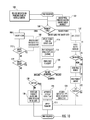
- FIG. 7 is a block diagram of a parking system according to an exemplary embodiment.
- FIG. 8A is a front view of a single-space parking meter according to an exemplary embodiment.
- FIG. 8B is an exploded view of a single-space parking meter according to an exemplary embodiment.
- FIG. 9 is a front view of an electronic meter mechanism according to an exemplary embodiment.
- FIG. 10 is a flow diagram showing the operation of a parking meter according to an exemplary embodiment.
- FIG. 11 is a flow diagram showing zeroing of a parking meter according to an exemplary embodiment.
- FIG. 12 is a flow diagram showing control of parking meter including a maximum time limit according to an exemplary embodiment.
- FIG. 13 is a block diagram showing an electronic meter mechanism according to an exemplary embodiment.
- FIG. 14 is a block diagram of a controller for a parking meter according to an exemplary embodiment.
- FIG. 15 shows a controller coupled to the main electronics board of a single-space meter according to an exemplary embodiment.
- FIG. 16 shows a controller incorporated in a stand-alone vehicle sensor according to an exemplary embodiment.
- FIG. 17 shows a controller configured for the control of two single-space parking meters according to an exemplary embodiment.
- FIG. 18 shows a detailed block diagram of a controller configured for the control of two sets of peripheral devices for two single-space parking meters according to an exemplary embodiment.
- FIG. 19 shows a controller configured to provide additional functionality as a retrofit for a single-space meter according to an exemplary embodiment.
- FIG. 20 shows a controller configured to function as a gateway for a parking system according to an exemplary embodiment.
- FIG. 21 shows a process for upgrading a single-space parking meter with a new electronic meter mechanism according to an exemplary embodiment.
- FIG. 22 is a front view of an electronic meter mechanism according to an exemplary embodiment.
- FIG. 23 is a side view of an electronic meter mechanism according to an exemplary embodiment.
- FIG. 24 is a rear view of an electronic meter mechanism according to an exemplary embodiment.
- FIG. 25 shows a process of upgrading a single-space parking meter with a new electronic meter mechanism according to an exemplary embodiment.
- FIG. 26 shows a meter housing cap following revision to accommodate an electronic meter mechanism that includes front and rear solar panels.
- FIG. 27 shows a perspective view of an electronic meter mechanism with a removable memory device according to an exemplary embodiment.
- FIG. 28 shows the electronic meter mechanism of FIG. 27 with the removable memory device removed according to an exemplary embodiment.
- parking system 10 includes one or more single-space parking meters 12 , one or more multi-space parking meters 14 , a communication network, shown as wireless network 16 , and a parking system control system, shown as parking management system 18 .
- Both single-space meters 12 and multi-space meter 14 may be configured to communicate with parking management system 18 by directly accessing wireless network 16 .
- wireless network 16 may be a mobile telephone system, and meters 12 and 14 may access wireless network 16 utilizing standard mobile telephone systems (e.g., GSM, GPRS, EDGE, 2.5G, 3G, 4G, etc.).
- meters 12 and 14 are configured to communicate parking meter data to parking management system 18 via wireless network 16 , and the communicated parking meter data is utilized by parking management system 18 to provide the parking system functionalities discussed herein.
- parking management system 18 is a computerized, server system that provides for processing, storage and management of data within parking system 10 .
- parking management system 18 includes at least one server 19 and wireless communications subsystem 21 .
- Server 19 is configured to store and process parking data associated with a particular parking spot (e.g., current parking space occupancy information, current meter time, vehicle sensor data, information regarding mode of payment, vehicle arrival information, vehicle departure information, parking rates, location information, etc.), including parking data received wirelessly from the meters, to generally provide the parking system functions discussed herein.
- Wireless communications hardware 21 of parking management system 18 is configured to allow server 19 to communicate wirelessly with the various components of parking system 10 discussed herein.
- server 19 is configured to store and generate data that may be communicated wirelessly to the various components of parking system 10
- wireless communication hardware 21 is configured to transmit system data or information from server 19 to the appropriate component of the parking system.
- wireless communications hardware 21 is configured to transmit and meters 12 and 14 are configured to receive information from parking management system 18 via wireless network 16 .
- the system data transmitted from parking management system 18 and received by the parking meters may include parking meter configuration data, parking rate data, time and date data, testing and diagnostic data, parking meter software updates, etc.
- a wired or a combination wired/wireless communication network may be used to provide communication to parking management system 18 .
- Parking system 10 also includes one or more vehicle sensors, shown as pole-mount vehicle sensors 20 , curb surface-mount sensor 22 and street surface-mount sensor 24 .
- sensors 20 , 22 and 24 are each associated with a single parking space 26 and are configured to detect the presence of a vehicle located in the associated parking space, to detect entry of a vehicle into the associated parking space and/or to detect the exit of a vehicle from the associated parking space.
- a pole-mount sensor 20 is associated with and in communication with each single-space meter 12
- sensors 22 and 24 are associated with and in communication with multi-space meter 14 .
- a subterranean sensor 28 see FIG.
- vehicle sensors 20 , 22 and 24 are directional sensors (i.e., sensor that only senses in a particular region or direction) and include a targetable detection zone. Generally, the vehicle sensors are positioned such that the targetable detection zone is located within the parking space associated with the meter and is not located in adjacent parking spaces.
- Vehicle sensors 20 , 22 , 24 and 28 are configured to detect one or more aspect (e.g., presence, entry, exit, etc.) of a vehicle within the parking spot associated with the sensor and to generate a signal indicative of the detected aspect of the vehicle. The generated signal is then communicated from the sensor to a controller associated with the parking meter for the parking spot.
- communication from the sensors to the associated meter may be either through wired or wireless communication.
- the parking meter may execute various functions in response to the detected aspect of the vehicle and may send data to and/or receive data from parking management system 18 in response to the detected aspect of the vehicle.
- data generated by the vehicle sensor associated with each meter e.g., data related to the presence of a vehicle within the space associated with the meter
- parking system 10 include a plurality of single-space meters 12 (e.g., 2, 3, 4, . . . 50, . . . 100, more than 2, more than 10, more than 20, more than 50, more than 100, etc., single-space meters), and may include one or more multi-space parking meters 14 .
- each single-space parking meter 12 includes a vehicle sensor, shown as vehicle sensor 20 , physically coupled to and supported by the parking meter pole 75 .
- pole 75 includes a lower end coupled to the ground adjacent to and set back from parking space 26 associated with the meter 12 such that there is a distance or space located between pole 75 and space 26 .
- vehicle sensor 20 coupled to pole 75 , a space is present between vehicle sensor 20 and parking space 26 , and vehicle sensor 20 is configured to detect an aspect of a vehicle located within parking space 26 across the space.
- vehicle sensor 20 includes a targetable detection zone 17 , and vehicle sensor 20 is positioned on pole 75 such that the detection zone 17 of vehicle sensor 20 is located within parking space 26 .
- vehicle sensor 20 may be physical coupled to and supported by the parking meter housing. In these embodiments, vehicle sensor 20 is located above both the street and sidewalk surface and is also set back from the curb.
- vehicle sensor 20 is communicably coupled with the control circuitry of single-space meter 12 (e.g., controller 200 shown in FIG. 13 ) directly via a dedicated hardwired connection.
- the robust electrical connection permitted by the proximity between the single-space meter electronics and vehicle sensor 20 allows for shared use of certain components.
- both the electronics of the single-space meter and vehicle sensor 20 share a common power supply (e.g., solar cells and battery).
- this arrangement allows both single-space meter 12 and vehicle sensor 20 to utilize a single set of wireless communications hardware.
- data generated by vehicle sensor 20 is communicated first to a control system associated with the mechanism of single-space meter 12 , and then is communicated to parking management system 18 via a wireless communication link.
- the hardwired connection between vehicle sensor 20 and single-space meter 12 is a combined data communication link and power connection delivering power to vehicle sensor 20 from a power source (e.g. batter, solar panel, etc.) physically located within the outer housing of the single space meter.
- a power source e.g. batter, solar panel, etc.
- parking system 10 may also include curb mount vehicle sensors 22 and/or street mount vehicle sensors 24 that communicate parking space usage information wirelessly to a multi-space meter 14 or to parking management system 18 .
- curb mount vehicle sensors 22 and/or street mount vehicle sensors 24 include their own power supply and communications hardware.
- curb mount vehicle sensors 22 and/or street mount vehicle sensors 24 are stand-alone sensors configured for short relatively short range wireless communication to a multi-space meter 14
- multi-space meter 14 is configured for cellular communication with parking management system 18 .
- FIG. 2 shows pole-mount vehicle sensor 20 .
- pole-mount vehicle sensor 20 includes a housing 30 having a central cavity 32 .
- the sensing element e.g., an electromagnetic energy transmitter and receiver, transceiver, etc.
- FIG. 1 shows a housing 30 having a central cavity 32 .
- the sensing element e.g., an electromagnetic energy transmitter and receiver, transceiver, etc.
- housing 30 of vehicle sensor 20 surrounds pole 75 , and the upper end of housing 30 is coupled to the lower end of the outer meter housing (e.g., outer meter housing 70 shown in FIG. 8 ).
- the wired communication link communicably coupling the sensing element of vehicle sensor 20 to the processor of the single space meter is located within both sensor housing 30 and the outer meter housing. Specifically the portion of the wired communication link coupled to the sensing element is located within sensor housing 30 and the portion of the communication link coupled to the processor of the electronic meter mechanism is located with the outer meter housing.
- Sensor housing 30 acts to protect and supports the sensing element and the wired connection to the electronic meter mechanism.
- vehicle sensor 20 does not include dedicated wireless communications hardware within sensor housing 30 .
- the vehicle sensors disclosed herein includes a local vehicle sensor processor the first processes the signal from the sensing element and then communicates the processed signal indicative of a vehicle in the parking space to a processor that controls the wireless communications hardware.
- FIG. 3 shows surface-mount sensors 22 or 24 that may be coupled to either the curb surface or the surface of the parking space using a suitable attachment mechanism, such as epoxy.
- FIG. 4 shows subterranean sensor 28 that may be located below the surface of parking space 26 . Similar to sensors 22 and 24 discussed above, subterranean sensor 28 communicates with meters 12 and 14 via a wireless connection and may be used in place of either sensor 22 or 24 in the parking system embodiments discussed herein.
- sensors 20 , 22 , 24 and 28 may be sensors configured to utilize electromagnetic energy to detect the presence of the vehicle in the parking space, and specifically, sensors 20 , 22 , 24 and 28 may be a radiofrequency (RF) sensor including a radiofrequency-based sensing element. In other embodiments, sensors 20 , 22 , 24 and 28 may be non-electromagnetic sensors In other embodiments, sensors 20 , 22 , 24 and 28 may be any sensors suitable for detecting an aspect of a vehicle in the associated parking space.
- RF radiofrequency
- sensors 20 , 22 , 24 and 28 may be infrared reflectance sensors, ultrasonic sensors, capacitance sensors, proximity sensors, magnetic sensors, magnetic-flux sensors, non-intrusive sensors, radar-based sensors, a low power/broad spectrum radar sensor, time of flight sensors, ranging sensors, etc.
- sensor 24 or sensor 28
- sensor 24 may be a weight sensor or movement sensor that is reactive to a vehicle in parking space 26 .
- vehicle sensors 20 , 22 , 24 and 28 may be configured to generate other signals related to the parking spot or vehicles located in the parking spot that may be used by parking system 10 .
- the vehicle sensors may be configured to generate a signal indicative of a vacant parking spot.
- the vehicle sensors may be configured to generate a signal indicative of the type of vehicle located in the parking spot.
- the vehicle sensor may be configured to generate a signal indicative of a motorcycle, a signal indicative of a car, a signal indicative of a truck, etc., being present in parking space 26 .
- the vehicle sensor may be configured to generate a signal indicative of a privately owned vehicle located in parking space 26 and a different signal indicative of a publicly-owned or government vehicle located in parking space 26 .
- a vehicle sensor may include a digital camera configured to capture image data of a vehicle located in the parking spot.
- parking system 10 may include one or more mobile citation units, shown as handheld unit 34 .
- Handheld unit 34 communicates with parking management system 18 via wireless network 16 .
- handheld unit 34 includes wireless communications hardware for communication with parking management system 18 via wireless network 16 .
- Handheld unit 34 is carried by parking enforcement personnel and is used to issue citations for parking violations.
- Handheld unit 34 sends various types of enforcement data (e.g., data indicating issuance of a citation, data related to the type of citation issued, location of parking violation, vehicle identification information, etc.) to parking management system 18 via wireless network 16 .
- Handheld unit 34 also receives various information from parking management system 18 .
- handheld unit 34 receives information to facilitate the issuances of citations.
- handheld unit 34 may receive data indicative of the existence and location of expired meters.
- handheld unit 34 may receive data regarding which meters within a certain distance from unit 34 are expired. It should be understood that while the figures show a handheld citation unit, other mobile citation units may be used within parking system 10 .
- a mobile citation unit may be mounted within a vehicle driven by enforcement personnel.
- data generated by the vehicle sensor associated with each meter may be communicated to parking management system 18 via the wireless communications hardware of the meter, and the data related to current space occupancy may be communicated from parking management system 18 to handheld unit 34 .
- the data generated by the vehicle sensors associated with each parking meter is processed to determine whether a vehicle is currently parked in the meter's parking space when time on the meter expires. If so it is determined that a parking violation has occurred. The single space meter then communicates data indicating that a parking violation has occurred to parking management system 18 .
- Parking management system 18 then stores and communicates the data indicating that a parking violation has occurred to the handheld unit 34 . This data then may be used by the enforcement personnel to issue a parking ticket. In one embodiment, following issuance of a parking ticket, data indicating that a parking ticket has been issued is communicated wirelessly from handheld unit 34 to parking management system 18 for processing and storage. In one embodiment, the data indicating that a parking ticket has been issued includes information identifying the vehicle (e.g., VIN, license plate information, etc.) that received the citation.
- VIN vehicle
- license plate information etc.
- parking system 10 provides a system utilizing wireless communication between the three major components or subsystems (e.g., the meters, the management system, and the citation units).
- the components in the field e.g., the meters and the citation units
- parking system 10 allows real-time data from meters system-wide to communicate information to parking management system 18 , which in turn allows up to date information regarding parking violations to be communicated to citation units 34 system wide.
- parking system 10 includes a plurality of single-space meters 12 each having a pole-mounted vehicle sensor 20 , a wireless network 16 and a parking management system 18 .
- This embodiment of parking system 10 includes a gateway 36 , and single-space meters 12 are configured for short-range communication with gateway 36 .
- gateway 36 provides the communication link between multiple meters 12 and parking management system 18 via wireless network 16 .
- single-space meters 12 are configured for short-range RF communication with gateway 36
- gateway 36 is configured for communication (e.g., cellular, WIFI, etc.) with parking management system 18 via wireless network 16 .
- Parking system 10 may also include one or more multi-space parking meter 14 in place of, or in addition to, single-space meters 12 .
- the multi-space meter may also communicate with gateway 36 using a wireless, RF technology.
- parking system 10 includes one or more stand-alone vehicle sensors, such as curb surface-mount sensor 22 and street surface-mount sensor 24 , configured to monitor occupancy of the parking spaces associated with multi-space meter 40 .
- gateway 38 receives wireless communication from both single-space meters 12 and the stand-alone vehicle sensors (i.e., sensor 22 and sensor 24 ). Similar to the embodiment shown in FIG. 5 , gateway 38 communicates information received from meters 12 and sensors 22 and 24 to parking management system 18 via wireless network 16 .
- Multi-space meter 40 communicates directly with parking management system 18 via wireless network 16 .
- parking management system 18 is configured to properly associate the data received from the stand-alone vehicle sensors with the data for the appropriate parking space received from multi-space meter 40 .
- parking system 10 may be configured to provide compatibility between parking meters made by different companies.
- parking meters 12 may be produced by a first company or manufacturer and multi-space meter 40 may be made by a second company or manufacturer.
- sensors 20 , 22 and 24 may be compatible with meters made by different companies.
- parking management system 18 is configured to receive, store and process data received from parking meters or vehicle sensors made by different companies. This allows current, installed single-space and multi-space meters manufactured by different companies to be upgraded to provide the wireless communications and vehicle sensing functionalities discussed herein.
- gateway 36 and gateway 38 may be mounted to an existing structure to provide for unobstructed transmission of RF signals from the meters to the gateways.
- a gateway may be mounted to a sign pole, or as shown in FIG. 6 , a gateway may be mounted to a light or utility pole.
- gateways 36 and 38 may be located at other locations such as a roof top, tree or other structure that allows for unobstructed RF communication from the meters or standalone vehicle sensors of parking system 10 . Further, gateways 36 and 38 may be located on a structure that provides for an AC power supply to power the gateway.
- gateways 36 and 38 may be housed within the housing of a multi-space meter or may otherwise be incorporated into the electronic system of the multi-space meter.
- the multi-space meter acts to receive information from the single-space meters and/or stand-alone vehicle sensors and communicates the information to parking management system 18 via wireless network 16 .
- gateways 36 and 38 may be mounted to and supported by the multi-space meter, for example by coupling the gateway housing to the exterior of the multi-space meter housing.
- parking system 10 may include a plurality of single-space parking meters 12 and one or more multi-space meters as discussed above.
- parking meter 12 includes a parking meter control system 50 , a communication subsystem 52 , a display 54 , a power supply 56 , a user input device 58 , a payment subsystem 60 and a vehicle sensor 62 .
- Parking meter control system 50 is communicably coupled to communication subsystem 52 , display 54 , power supply 56 , user input device 58 , payment subsystem 60 and vehicle sensor 62 .
- Parking meter control system 50 may generally be any electronic control unit suitable to provide the various parking meter functionalities discussed below.
- control system 50 may include one or more processing circuits having hardware (e.g., processors, memory, communication interfaces, etc.) and/or software configured to control the operation of parking meter 12 as discuss herein.
- control system 50 includes two processors that each control various device of meter mechanism 72 .
- Communication subsystem 52 includes hardware and/or software for communicating data between parking meter control system 50 and parking management system 18 via wireless network 16 .
- communication subsystem 52 may be a communication subsystem associated with a single-space parking meter 12 that is configured to communicate data between the associated meter and parking management system 18 via wireless network 16 utilizing standard mobile telephone communication systems (e.g., GSM, GPRS, EDGE, etc.).
- standard mobile telephone communication systems e.g., GSM, GPRS, EDGE, etc.
- communication subsystem 52 may include RF communication hardware and software physically coupled to single-space parking meter 12 and/or associated with a stand-alone vehicle sensor and a gateway, such as gateway 36 and 38 .
- communication subsystem 52 includes a wireless communication antenna that is supported, and may be directly supported, by the inner housing of the electronic meter mechanism.
- Single-space meter 12 also includes a display 54 that displays various parking related information (e.g., parking rate, current time and date, time remaining on meter, a meter expired message, user operation instructions, hours of meter operation, etc.) to the user of single-space meter 12 .
- Display 54 may be a graphical high contrast, low power display. The display may be color or monochrome.
- Display 54 may be an LED display or LCD display. In the embodiment shown best in FIGS. 22 and 24 , display 54 includes both a front facing screen on the sidewalk facing side of the meter and a rear facing screen on the street facing side of the meter.
- Single-space meter 12 also includes a power supply 56 suitable to power the functions of single-space meter 12 discussed herein.
- power supply 56 may include one or more solar cells or solar panels and one or more self-sustained energy storage devices (e.g., rechargeable batteries, ultracapacitors, etc.).
- power supply 56 may be wired AC power supply.
- single-space meter 12 may be configured to communicate power supply data wirelessly to parking management system 18 via the meter's wireless communication hardware.
- Power supply data may include data related to a battery and/or solar cell of the meter (e.g., battery charge rate, remaining battery charge, remaining battery life, real-time current supplied by solar cell, average current supplied by solar cell, resistance at various sections within the power supply, error messages indicating battery failure, error messages indicating solar panel failure, real-time power consumption, average power consumption, etc.).
- single space meter 12 and/or electronic meter mechanism 72 may include one or more sensors configured to detect vandalism.
- the vandalism sensors may be associated with the electronic meter mechanism, the outer housing of the meter, the meter pole and/or the sensor housing.
- the vandalism sensors may be configured to detect a strong impact (such as a hit from a crowbar) or the insertion of a tool into the coin slot or key hole associated with the meter.
- the vandalism sensor may include or more of a vibration sensor, an acceleration sensor, optical sensors and/or acoustic sensors.
- Single-space meter 12 also includes a user input device 58 that allows the user to interact with and operate the meter.
- user input device 58 is a four button keypad that provides tactile feedback and/or audible feedback to the user.
- Single-space meter 12 also includes a payment subsystem 60 configured to receive and process payment for parking.
- payment subsystem 60 includes currency reader (e.g., a money or coin slot and a money detector, a bill slot and bill detector, etc.), a credit-card, mag-strip reader, a smart card reader, and/or a “pay by phone” system.
- single-space meter 12 also includes a vehicle sensor 62 (e.g., pole-mount vehicle sensors 20 , curb surface-mount sensor 22 and street surface-mount sensor 24 as shown in FIGS. 1 , 5 and 6 , and/or sensor 28 shown in FIG. 4 ) that communicates information to control system 50 regarding an aspect of a vehicle in the parking space associated with meter 12 .
- vehicle sensor 62 e.g., pole-mount vehicle sensors 20 , curb surface-mount sensor 22 and street surface-mount sensor 24 as shown in FIGS. 1 , 5 and 6 , and/or sensor 28 shown in FIG. 4 .
- single-space meter 12 is shown according to an exemplary embodiment.
- single-space meter 12 includes an outer housing 70 and an electronic meter mechanism 72 (shown outside of outer housing 70 in FIG. 9 ).
- Outer housing 70 acts to protect electronic meter mechanism 72 and includes a locking mechanism to prevent unwanted access to meter mechanism 72 .
- Outer housing 70 includes a lower housing portion 71 and a cap portion 73 .
- Cap 73 of outer housing 70 includes a transparent portion or window 74 which allows the user to view the display of electronic meter mechanism 72 when it is locked within outer housing 70 .
- Lower portion 71 of outer housing 70 is coupled to an upper end of a support structure or pole 75 that supports meter 12 .
- Lower portion 71 of outer housing 70 has an interior cavity 77 and a front (i.e., sidewalk facing) face 76 having a payment device opening, shown as an aperture 78 .
- electronic meter mechanism 72 is received within cavity 77 and cap 73 is coupled to lower portion 71 such that electronic meter mechanism 72 is secured within housing 70 .
- Electronic meter mechanism 72 is shown outside of meter housing 70 .
- Electronic meter mechanism 72 includes an inner housing 80 that supports the various components and electronics of electronic meter mechanism 72 .
- Inner housing 80 is generally the shell or structure the encases and supports the electronics of meter mechanism 72 .
- Inner housing 80 also couples to the inner surface of outer housing 70 such that electronic meter mechanism 72 may be supported by and secured to outer housing 70 .
- electric meter mechanism 72 includes an electronic display screen, shown as display 54 , that displays information to the user.
- display 54 includes a first screen viewable from the front of meter mechanism 72 and a second screen viewable from the rear of meter mechanism 72 .
- meter mechanism 72 includes a payment receiving structure including one or more payment devices configured to receive payment from a motorist (e.g., a credit card reader, a currency reader, a smart card reader, etc.).
- meter mechanism 72 includes a user input device (e.g., a keypad, touch screen, buttons, switches, etc.) that receives inputs from the motorist in order to operate the parking meter.
- the payment receiving structure and the user input device is located on the front side of the inner housing such that the motorist is located on the sidewalk when applying payment to the meter or interacting with the user input device.
- the exemplary embodiment of electronic meter mechanism 72 shown in FIG. 9 includes an integrated payment and user-interface structure 82 that extends outward from the front side of inner housing 80 .
- Structure 82 includes both at least the physical, payment receiving components of both the payment subsystem 60 and the user input device 58 .
- Structure 82 is an extended portion of the housing that supports both the payment receiving structure and the user input device of meter mechanism 72 .
- user input device 58 is a four button interface including up and down arrow keys, an OK button and a cancel button.
- Payment subsystem 60 includes a hybrid card reader including both a smart card reader 84 and a credit card mag strip reader 86 .
- Payment subsystem 60 also includes a money slot, shown as coin slot 88 , and located within structure 82 is a currency reader that detects currency (coins in the example shown) that passes through coin slot 88 .
- the money slot and currency reader may be configured to accept and detect paper money.
- Smart card reader 84 may be configured to read a variety of smart-card type payment cards, for example, smart-card credit cards, smart-card debit cards, proprietary parking payment smart cards, etc.
- Credit card reader 86 may be configured to read a variety of mag-strip based payment cards, including, mag-strip credit cards, mag-strip debit cards, proprietary parking mag-strip payment credit cards, etc.
- payment subsystem 60 also includes an RF based payment system configured to read an RFID tag associated with the vehicle (e.g., iPass), and to process a parking payment to a pre-registered account associated with the vehicle's RFID tag.
- inner housing 80 includes a first arm or portion 280 and a user input housing, shown as keypad housing 282 .
- Arm portion 280 extends substantially perpendicular from the front face of inner housing 80
- keypad housing 282 is coupled to the front edge of portion 280 and extends downward away from portion 280 .
- the keys of the keypad form the front face of keypad housing 282 .
- the keys of user interface 58 are located below the coin slot 88 and is located below a majority of the credit card slot of credit card reader 86 .
- a gap 284 (shown best in FIG. 23 ) is formed between the front surface 286 of inner housing 80 and the rear surface 288 of keypad housing 282 .
- the front surface of outer housing 70 below aperture 78 is received within gap 284 such that integrated payment and user-interface structure 82 extends through outer housing 70 (as shown in FIGS. 8A and 8B ).
- This arrangement may help to secure meter mechanism 72 to housing 70 and may help to properly locate electronic meter mechanism 72 relative to the outer meter housing during installation.
- the length of arm portion 280 is such that rear surface 288 of keypad housing 282 is in contact with and flush against the front surface of outer housing 70 below aperture 78 when meter mechanism 72 is within housing 70 .
- the portion of integrated payment and user-interface structure 82 that includes the mag-strip reader of credit card reader 86 extends outward from front face 286 of inner housing 80 beyond key pad 58 .
- the extended length of the housing portion that supports mag-strip reader of credit card reader 86 in the direction perpendicular to the front face of inner housing 80 provides sufficient length to allow full insertion of a credit card into the credit card reader.
- This relative sizing allows meter mechanism 72 to include an upgraded payment system (e.g., one including a credit card reader) and to be installed in a pre-existing outer meter housing 70 .
- credit card reader 86 includes a slot 87 formed in the front face of structure 82 .
- Slot 87 provides the entrance that allows a credit card to be inserted into and to be read by the mag-strip reader of credit card reader 86 .
- slot 87 is angled at an angle A relative to the vertical axis of the front face of structure 82 .
- slot 87 is angled such that the upper end of the slot is located laterally inward from the lower end of the slot.
- Slot 87 extends downward and laterally outward from its upper end to its lower end.
- angle A is between 30 degrees and 80 degrees, preferably between 40 and 70 degrees and more preferably between 50 and 60 degrees.
- angle A is about 55 degrees (e.g., 55 degrees plus or minus half a degree).
- slot 87 extends below and laterally to the outside of the upper edge of the keypad. In other embodiments, slot 87 may angled in the opposite direction such that the upper end of the slot is located laterally outward from the lower end of the slot. Because the length of slot 87 is determined by the size of the type of credit card to be read, angling slot 87 allows for conservation of space on the front face of structure 82 .
- front facing surface 290 of keypad housing 282 includes the buttons of user interface 58 .
- front facing surface 290 is at an angle relative to surface 286 and to the vertical plane defined by display 54 , such that front facing surface 290 is facing slightly upward.
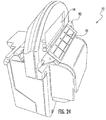
- electronic meter mechanism 72 includes a front solar panel 90 that provides power to operate electronic meter 72 and to charge a rechargeable battery located inside inner housing 80 .
- Inner housing 80 includes a front support, shown as front shelf 92 , upon which front solar panel 90 is mounted. Further, shelf 92 extends from the front surface (i.e., the sidewalk facing surface) of inner housing 80 and is positioned below (i.e., at a lower position as measured along the vertical axis of the meter mechanism) display 54 such that shelf 92 is located below window 74 of outer housing 70 . In this embodiment, shelf 92 is also located above structure 82 .
- shelf 92 is coupled to the front side of inner housing 80 at a position substantially underneath (i.e., at a position below along the same vertical axis) display 54 .
- This arrangement allows electronic meter mechanism 72 to be mounted inside outer housing 70 while allowing sunlight to strike front solar panel 90 .
- this positioning of solar panel 90 allows meter mechanism to be installed into a pre-existing meter housing in a configuration that allows sun light to reach panel 90 after the meter mechanism is secured within outer housing 70 .
- shelf 91 and solar panel 90 are positioned relative to the windows in the meter housing cap to maximize solar irradiance during normal operation.
- electronic meter mechanism 72 also includes a rear solar panel 91 .
- Rear solar panel 91 is mounted to a rear shelf, shown as shelf 93 , which extends from a rear surface of inner housing 80 at a position below display 54 .
- shelf 93 which extends from a rear surface of inner housing 80 at a position below display 54 .
- rear solar panel 91 is also mounted to inner housing 80 such that light may pass through a rear window in meter housing 70 to strike rear solar panel 91 .
- electronic meter mechanism 72 may include one solar panel or more than two solar panels.
- Both solar panel support shelves 92 and 93 extend outward away from display 54 and downward toward structure 82 and toward the lower edge of the meter housing.
- This arrangement is such that the upper surfaces of shelves 92 and 93 are angled (e.g., are non-horizontal, are not perpendicular to a vertical axis, etc.) such that the surfaces of both shelves face upward and outward away from display 54 .
- This positioning provides mounting surfaces for solar panels 90 and 91 that facilitate capture of light through the windows 74 of outer housing 70 .
- Display 54 may be a backlit high-contrast display supporting the display of both text and graphics.
- Display 54 may be a monochrome display or a color display.
- display 54 is supported by inner housing 80 at a position above (i.e., at a higher position as measured along the vertical axis of the meter mechanism) payment and user interface structure 82 .
- display 54 includes a left edge and a right edge, and in the embodiment shown, display 54 is rectangular having upper and lower edges perpendicular to both the left and right edges.
- the width of solar panels 90 and 91 is greater than the width of display screen 54 such that the left and right lateral edges of solar panels 90 and 91 extend laterally beyond the left and right edges of display 54 , respectively.
- Electronic meter mechanism 72 is configured to provide wireless communication from the meter to parking management system 18 .
- electronic meter mechanism 72 may include cellular communications hardware (e.g., GPRS modem, antenna, etc.) located within and/or coupled to inner housing 80 .
- electronic meter mechanism 72 includes RF communications hardware (e.g., point-to-multipoint RF modem, antenna, etc.).
- electronic meter mechanism 72 includes both cellular communications hardware and RF communications hardware allowing the mechanism to be incorporated into either systems using a gateway or using direct meter cellular communications.
- electronic meter mechanisms 72 within parking system 10 may be configured to utilize multi-point to multi-point or mesh networking communication systems.
- electronic meter mechanisms 72 may be configured to connect to a primary gateway.
- parking system 10 may be configured to determine the shortest and/or most reliable path through one or more gateways to reach parking management system 18 .
- networked meter mechanism 72 may be configured to detect or discover those gateways that are in range.
- a node may send a first message to discover a gateway, and the gateways within range may respond back at random intervals within a predetermined time window. The node will then evaluate the link to the gateway and through the gateway (or gateways) to assess and select the shortest and/or most reliable path to the server.
- Parking system 10 may utilize the vehicle sensing features and the communication features described above to provide for various automated and real-time parking system functions.
- FIG. 10 is a flow diagram showing the operation of single-space meter 12 and display 54 by the meter controller and parking management system 18 during the payment sequence of the parking meter.
- parking system 10 may be configured to automatically initiate the beginning of the payment sequence and the display of the appropriate instructions on display 54 based upon detection of a vehicle within the parking space by the vehicle sensor.
- a vehicle is detected by the vehicle sensor, a signal is communicated from the sensor to the meter controller (e.g., parking meter control system 50 ), and the meter controller initiates display of the payment instructions.
- the meter controller e.g., parking meter control system 50
- the meter controller also initiates display of the payment instructions.
- the meter displays a message asking the user to select the type of payment the user wishes to use. In the embodiment of FIG. 10 , the user may select payment by coin, payment by credit card, payment by smart card or pay-by-phone options.
- parking meter control system 50 is configured to allow a vehicle to park in the space associated with the meter for a set “grace period” prior to moving to step 104 .
- parking meter control system 50 is configured to allow a set amount of free parking time prior to requiring payment to be applied to the meter.
- free time (e.g., 15 minutes, 20 minutes, 30 minutes, etc.) may be automatically applied to the meter when a vehicle is detected in the parking space by a vehicle sensor at step 100 .
- the motorist may add additional time via payment as discussed below.
- the meter displays instructions for the selected payment type, and the user follows the instructions to put the appropriate amount of time on the parking meter, and the meter processes the payment received by the user to apply the payment to the meter.
- the user or motorist may insert coins, and at step 106 , the single-space meter detects the coins added to the meter.
- the meter control system adds the appropriate amount of time for the coins deposited to the meter and displays the amount of time on the screen.
- the single-space meter detects whether additional coins have been added and if so the meter time is updated as needed.
- the single-space meter detects whether user has attempted to add time using one of the other payment methods, and if so, the payment processing for a smart card or credit card is conducted. If no additional payment is detected, the payment is applied to the meter at step 114 and the single-space meter monitors the time remaining on the meter and awaits for input.
- the motorist may add time to the meter using a credit card, and at step 116 , the single-space meter detects whether a credit card has been inserted into the credit card reader.
- the meter prompts (e.g., by the display of instructions on screen 54 ) the user to use the up and down arrow keys to select the amount of time the user wishes to add to the meter.
- the single-space meter detects the user's activation of the enter or OK button, at step 120 .
- the single-space meter submits the transaction data for authorization of the credit card.
- the meter determines whether batching of the credit card transaction is available.
- step 124 the total time added to the meter is displayed, and the payment is applied to the meter at step 114 and the single-space meter monitors the time remaining on the meter and awaits for input. If batching is not available, the meter displays a message that credit card payment is unavailable at step 130 .
- the user may select the pay by phone options, and the meter displays instructions to the motorist regarding payment by phone.
- the payment by phone number is displayed to the motorist.
- the meter number is entered, and at step 136 , the communication type is determined. If MSM communication is selected, at step 138 the space number is entered.
- the user is prompted to enter the amount of time to be added to the meter, and the payment is applied to the meter at step 114 and the single-space meter monitors the time remaining on the meter and awaits for input.
- the user may selected whether receive text reminders indicating the amount of time left on the meter.
- the vehicle sensor is configured to communicate a signal to the meter controller indicative of whether a vehicle has left the parking space.
- the vehicle sensor associated with a parking spot detects that the current vehicle is leaving the parking space.
- the time remaining on the meter for the parking spot is set to zero by the controller after the current vehicle leaves the parking space. Zeroing the time on the meter when the current vehicle leaves the parking space may lead to an increase in parking revenue by preventing a subsequent parker from utilizing meter time from a previous parker.
- the parking meter may be a single-space meter, and the signal indicative of the vehicle leaving the parking spot is communicated to the parking meter control system associated with that meter.
- the parking meter control system zeros out the display of remaining time on the meter.
- the vehicle sensor is physically coupled to the meter or the meter pole and communicates the signal via a hardwired connection to the single-space meter controller.
- the vehicle sensor may be a stand-alone vehicle sensor associated with a multi-space meter, and in this embodiment, the signal indicative of the vehicle leaving the parking spot may be communicated to the parking meter control system associated with the multi-space meter. In this embodiment, the controller of the multi-space meter may zero out the time associated with the parking spot. In another embodiment, the vehicle sensor may communicate the signal indicative of the vehicle leaving the parking spot directly to the parking management system. In this embodiment, the time associated with the parking space as maintained by the parking management system may be set to zero. Further, the parking management system may transmit a signal to the multi-space meter indicating that the time associated with the parking space should be set to zero.
- the parking meter control system communicates parking space data to the parking management system.
- the parking space data communicated to the parking management system may include various parking space information including information related to vehicle departure, information indicating a vacant parking space, information indicating that no time is left on the meter, information indicating the length of time that the vehicle was parked in the parking spot, etc. This data may be utilized by the parking management system (e.g., parking management system 18 ) to provide the various functions discussed herein.
- parking system 10 either through local processing of parking data at meters 12 or 14 or through centralized processing at parking management system 18 , is configured to utilize parking data to enforce maximum parking time limits.
- FIG. 12 a flow-diagram of a process for the enforcement of a maximum parking time limit is shown. The process shown may be performed either by local processing of data at the control system of the single-space or multi-space meter or by centralized processing of data by the parking management system.
- the control system receives a signal indicating that a user is attempting to add additional time to the parking meter using one of the payment methods discussed above.
- the control system checks to determine whether exit information has been received and stored. If it has, it is determined that a new vehicle is located in the parking spot, and at step 164 , the user is allowed to add time to the parking meter.
- step 166 the amount of time that the current vehicle has been parked in the parking spot is determined and is compared to the maximum permitted parking time for the meter. If the current parking duration does not exceed the maximum permitted parking time for the parking space, the process moves to step 168 and the user is allowed to add time to the meter. At step 170 , if the current parking duration does exceed the maximum permitted parking time, the parking meter will not accept additional payment and will not add additional time to the meter. Further at step 170 , a message may be displayed to the user via display 54 indicating that the maximum permitted parking time has been met.
- parking system 10 gathers parking related information from each of the vehicle sensors associated with each parking space and from the parking meter associated with each parking space. This information is communicated to parking management system 18 which stores and process the parking information.
- parking management system 18 receives real-time parking information from each of the parking meters and each stand-alone vehicle sensor via wireless network 16 .
- Real-time parking information includes parking space occupancy information (e.g., whether or not a particular parking space is currently occupied by a vehicle), vehicle arrival information, and vehicle departure information.
- Real-time parking information may also include parking meter status information, for example, information regarding whether the meter is expired, unexpired, the amount of time remaining on the meter, etc.
- Wireless communication between the parking management system and the field devices e.g., the parking meters and the mobile devices carried by enforcement personnel and motorists) allows for real time parking information to be processed and deployed to provide the functionality discussed below.
- parking management system 18 communicates meter status information in real-time to users within the parking system. In one such embodiment, parking management system 18 transmits real-time information regarding expired, occupied parking spaces to parking enforcement personnel. The parking enforcement personnel may use the received data to issue citations, to plan a meter inspection route, etc.
- parking enforcement personnel receive the real-time information via wireless communication between handheld unit 34 and parking management system 18 .
- parking management system 18 may be configured to identify expired meters in real-time and to send information to a parking enforcement agent in real-time. When the parking enforcement agent receives the real-time information regarding expired meters, the parking enforcement agent may travel to the expired meter to issue a citation.
- parking management system 18 may be configured to automatically generate a route for the parking enforcement agent to follow based on real-time identification of the location of expired meters and transmit the route information to handheld unit 34 or other mobile device used by the enforcement agent. Further, parking management system 18 may be configured to select the route based on various parameters.
- the enforcement agent's route may be identified by parking management system 18 to maximize the number of citations issued, to minimize the route distance or to minimize the route travel time.
- the parking enforcement agent may select the type of route they wish to follow using handheld unit 34 .
- Parking management system 18 may also be configured to communicate real-time meter status information to motorists to facilitate location of an unoccupied parking meter.
- parking management system 18 is configured to communicate information indicative of unoccupied parking spaces to a personal navigation system (e.g., a mobile device utilizing map software, a vehicle having a GPS navigation system, a mobile device having GPS navigation software, etc.).
- the personal navigation system is configured to display the location of unoccupied parking spaces based on the real-time meter status information received from parking management system 18 . For example, a listing of unoccupied parking spaces may be displayed and/or the location of the unoccupied parking spaces may be displayed on the map.
- the user may select the desired parking space, and the personal navigation system then generates a route from the current location to the selected parking space based on the real-time meter status information received from parking management system 18 .
- the personal navigation system may utilize a user input to determine current position information.
- the personal navigation system may be configured to automatically identify current position information by accessing positioning information, such as GPS.
- the personal navigation system is configured to display an alert to the user if the parking space becomes occupied by another driver before the user arrives at the parking spot, and in one such embodiment, the personal navigation system may automatically reroute the user to the next nearest unoccupied parking spot based on the real-time meter status information received from parking management system 18 .
- information indicative of unoccupied parking spaces may be aggregated based on a particular geographic area by parking management system 18 .
- the parking management system 18 may be configured to generate information of parking space occupancy for a geographic area instead of or in addition to generating the location of particular unoccupied parking spots.
- a map may be displayed by a mobile device showing the general availability of parking spaces in a given block or other area based on the geographic parking space occupancy information received from parking management system 18 .
- the number of available parking spots in a block may be displayed on a map of the personal navigation system.
- the number of available parking spots between two cross-streets along the person's route may be displayed based on the geographic parking space occupancy information received from parking management system 18 .
- an indication of the occupancy rate of parking spaces along the user route may be displayed based on the geographic parking space occupancy information received from parking management system 18 .
- the parking space occupancy rate may be displayed utilizing a color-coded system. For example, streets with 100% occupancy may be highlighted in red on the map display, streets with 90-99% occupancy may be highlighted in orange on the map display, streets with 75%-89% occupancy may be highlighted in yellow on the map display, and streets with occupancy under 75% may be highlighted in green on the map display.
- the personal navigation system is configured to display information indicative of the proximity of each identified unoccupied parking spot to the user's ultimate destination based on the real-time meter status information received from parking management system 18 .
- a listing of unoccupied spaces may be ordered by distance from the parking spot to the user's destination.
- a display of unoccupied parking spaces on the personal navigation system map may include a display of distance information next to the location of the parking space on the map.
- a flag display indicating the location of the unoccupied parking space may include a number indicating the distance from the parking space to the destination.
- the flag display may include a number indicating the distance rank of each unoccupied parking space to the user's destination (e.g., 1 for first closest, 2 for second closest, 3 for third closest, 4 for fourth closest, etc.).
- Parking management system 18 may also be configured to store parking information received via wireless communication from the meters of parking system 10 .
- parking information may be manually entered into parking management system 18 .
- parking information may be loaded into parking management system 18 from another data source (e.g., memory unit of handheld device 34 ).
- Parking management system 18 may include storage components and database components to store and organize the received parking information. The historic, stored parking information within parking management system 18 may be analyzed to operate or to improve operation of parking system 10 .
- parking space occupancy information may be analyzed by parking management system 18 to adjust the parking rate of a particular meter. For example, if a meter is occupied at more than a desired level (e.g., close to 100% of the time) the parking rate of the meter may be increased, and if the meter is occupied at a less than desired level (e.g., less than 50% of the time) the parking rate may be decreased. The change in parking rate is determined by parking management system 18 and the new rate is communicated wirelessly to the meter.
- parking management system 18 may be configured to process occupancy data to determine what parking rate would result in a desired occupancy rate.
- the desired occupancy rate may be between 60 and 90 percent, may be between 70 and 90 percent, may be between 75 and 85 percent or may be about 80 percent.
- parking management system 18 may be configured to automatically process occupancy data to determine the parking rate that would result in the desired occupancy rate, and parking management system 18 may be configured to automatically communicate the determined parking rate to the parking meter thereby setting the meter's current parking rate to match the determined rate.
- the parking rate of one or a plurality of meters within that geographic area may be increased, and if one or more meters are occupied at a less than desired level (e.g., less than 50% of the time), the parking rate of one or a plurality of meters within that geographic area may be decreased.
- a desired level e.g., close to 100% of the time
- parking management system 18 may be configured to process occupancy data for a predetermined time period and to determine the parking rate that would result in the desired occupancy rate for the predetermined time period.
- parking management system 18 is configured to process occupancy data for a particular predetermined time period (e.g., week day days, week day nights, weekend days, weekend nights, holidays, days or hours of special events, like sporting events, etc.) and to determine the parking rate that results in the desired occupancy rate during the predetermined time period. Parking management system 18 then communicates this information wirelessly to each meter to change the parking rate of the meter.
- the historical parking data may be analyzed by parking management system 18 to improve parking enforcement efforts.
- parking management system 18 may be configured to determine if a disproportionate number of parking violations are identified historically in a particular area and/or during a particular time period, and if so, parking management system 18 provides an indication that enforcement efforts should be increased during those times. For example, the indication may be displayed data indicating where enforcement efforts should be increased.
- parking management system 18 may automatically communicate information regarding a particular enforcement patrol route based on the analysis of historic parking data by parking management system 18 . However, if a disproportionately small number of parking violations are identified during a particular time period or in a particular area, parking enforcement resources may be diverted to other areas of parking system 10 by parking management system 18 .
- parking management system 18 may be configured to process historical parking data to determine desired parking enforcement routes, to determine the number of enforcement personnel that should be assigned to a particular area during a particular time, etc.
- parking management system 18 may be configured to utilize wirelessly communicated payment data to provide additional functionality to parking meter system 10 .
- parking management system 18 may be configured to evaluate or analyze payment data received from single space meters 12 (e.g., data regarding payments received from credit cards, smart cards, debit cards, pay-by-phone devices, near-field-communication payment devices, etc.) to identify suspicious or fraudulent payment activity.
- parking management system 18 may be configured to identify a payment pattern that indicates fraudulent payments. For example, parking management system 18 may be configured to identify that a particular payment device (e.g., a particular credit card, smart card, cell phone, etc.) has been used to pay for a number of meters in an irregular pattern.
- a particular payment device e.g., a particular credit card, smart card, cell phone, etc.
- payment devices that are associated with a fraudulent payment pattern can be flagged and added to a real-time “blacklist” maintained by parking management system 18 .
- payment approval processing performed by parking management system 18 may include comparing a payment device to devices listed on the blacklist, and subsequent payments from blacklisted payment devices can be denied.
- parking management system 18 may maintain a list of payment devices (e.g., particular brands of credit cards, particular credit cards owned by identified individuals, etc.) that are entitled to a parking discount or free additional parking time.
- an identifier associated with the payment device or the owner of the payment device may be compared against the discount list maintained by parking management system 18 and a discount applied accordingly.
- electronic meter mechanism 72 includes two distinct processors, shown as peripheral device and communication controller 200 and single-space meter (SSM) controller 202 , and the local processing and control functions of electronic meter mechanism 72 are divided between the two processors.
- SSM controller 202 conducts the processing for and controls the display 204 , a user input device, such as keypad 216 or input device 58 shown in FIG.
- control of the additional components of electronic meter mechanism 72 may be split between the two processors 200 and 202 as shown below in FIG. 13 .
- both controllers 200 and 202 are controllers specifically configured for control of certain components of a new electronic meter mechanism.
- controller 200 is a multi-purpose or multi-use control/communication device that is communicably coupled a dedicated single-space meter controller 202 in order to supplement the functionality provided by SSM controller 202 and to equip electronic meter mechanism 72 with additional peripheral devices that are not controlled by SSM controller 202 .
- SSM controller 202 is a dedicated single-space meter controller and is coupled to, interfaces and/or controls a user display 204 , a money sensor 206 , a smart card reader 208 and keypad 216 .
- SSM controller 202 is the controller present in a conventional electronic single-space parking meter and controller 200 is communicably coupled to SSM controller 202 along with additional components shown in FIG. 13 (e.g., elements 210 , 212 , 214 and 218 ) as a retrofit unit to provide additional functionality to the meter.
- the division of control between two processors may provide electronic meter mechanism 72 with a higher efficiency and lower power requirement, than if one single processor were used.
- both controllers 200 and 202 have a low power state and a high power state, and the controllers are configured to be in a low power state when the devices its control are not active and in the high power state when the devices under its control are active.
- controller 202 may transition from the low power to the high power state when data is to be received or transmitted using the wireless communications hardware.
- single space meter controller 202 controls the time keeping functions of single space meter 12
- controller 200 is configured to control display 204 and to receive signals from money sensor 206 , smart card reader 208 and keypad 216 in addition to the management of wireless communication sub-system 210 , vehicle sensor 214 and credit card reader 218 , discussed herein.
- SSM controller 202 controls display of information on display 204 and also receives and process input signals received from keypad 216 .
- SSM controller 202 is configured to receive information from keypad 216 .
- SSM controller 202 may use this data to alter the display of information on display 204 based on the user inputs and to operate the payment receipt functions of the meter.
- keypad 216 may be a four button keypad that allows the user to operate the parking meter.
- SSM controller 202 may communicate information received from keypad 216 to controller 200 , and controller 200 may in turn communicate the information to parking management system 18 via wireless communication subsystem 210 .
- SSM controller 202 receives an input signal from money sensor 206 indicating when a user has placed money into the parking meter.
- Money sensor 206 may include an inductive coil sensor configured to detect that presence and denomination of coin placed in the coin slot of the meter.
- money sensor 206 may be an optical sensor associated with a coin slot configured to detect the presence and the denomination of coins placed in the coin slot of the meter.
- money sensor 206 may incorporate an inductive coin sensor to detect money entering the coin slot and an optical sensor to detect a jam or foreign object located within the coin slot.
- Money sensor 206 may also include an optical sensor associated with a paper money slot configured to detect the presence and the denomination of paper money placed into the paper money slot of the meter.
- SSM controller 202 also receives input from smart card reader 208 indicating that the user has paid for parking using a smart card.
- Peripheral device and communication controller 200 may be communicably coupled to a variety of additional parking meter devices to supplement the functionality provided by SSM controller 202 .
- controller 200 is coupled to, interfaces and/or controls a wireless communication subsystem 210 , a power supply system 212 , a vehicle sensor 214 , and a credit card reader 218 .
- electronic meter mechanism 72 is provided with the functionalities provided by wireless communication subsystem 210 , power supply system 212 , vehicle sensor 214 , user interface keypad 216 , and credit card reader 218 .
- Controller 200 controls wireless communication subsystem 210 to provide electronic meter mechanism 72 with wireless communication functionality.
- wireless communication subsystem 210 provides the communication hardware and software that allows meter mechanism 72 to send information to and to receive information from parking management system 18 .
- Signals indicating that payment has been received from money sensor 206 or smart card reader 208 may be communicated from SSM controller 202 to controller 200 , and controller 200 may in turn communicate this information to parking management system 18 utilizing wireless communication subsystem 210 .
- controller 200 may communicate information received from power supply 212 , vehicle sensor 214 and credit card reader 218 to parking management system 18 using wireless communication subsystem 210 .
- controller 200 may communicate data to the SSM controller 202 that indicates the receipt of a credit card payment has been received, and SSM controller 202 is configured to add time to the meter and to display additional time based upon the data related to the receipt of credit card payment.
- wireless communication subsystem 210 may include hardware and software to communicate directly with parking management system 18 via cellular telephone communication standards.
- wireless communication subsystem 210 may utilize an RF based communication standard to communicate with a gateway which in turn communicates with parking management system 18 .
- Controller 200 interfaces with power supply 212 to provide power to the components of electronic meter mechanism 72 .
- power supply 212 includes a rechargeable battery 220 and one or more solar cells or solar panels 222 (e.g., front solar panel 90 and/or rear solar panel 91 ).
- Battery 220 may be one or multiple batteries and may power both controller 200 and SSM controller 202 and the components coupled to each controller.
- Solar panel 222 is coupled to battery 220 and acts to recharge battery 220 .
- Solar panel 222 is physically located on the housing of meter mechanism 72 such that it may receive sunlight transmitted through the window located on the front and or rear surfaces of the outer housing of the meter.
- Controller 200 may receive data related to various operating states of power supply 212 and may communicate this data to parking management system 18 via wireless communication subsystem 210 .
- controller 200 may receive data regarding the charge state of battery 220 , recharge rate of battery 220 , the recharge effectiveness or efficiency of solar cell 222 , etc. This data may be processed by parking management system 18 to determine whether a battery and/or solar cell in a particular single-space meter needs to be replaced.
- Controller 200 also interfaces vehicle sensor 214 .
- Vehicle sensor 214 may be pole-mount vehicle sensors 20 , curb surface-mount sensor 22 or street surface-mount sensor 24 discussed above, or any other sensing device suitable for vehicle detection of the past, present or future.
- Vehicle sensor 214 generates a signal indicative of the vehicle located in the parking spot associated with electronic meter mechanism 72 and communicates the signal to controller 200 .
- Controller 200 may communicate information related to the vehicle in the parking space to SSM controller 202 , and SSM controller 202 may use this information to operate the devices under its control.
- display 204 may be updated by SSM controller 202 based on the information from vehicle sensor 214 to prompt the user of the parking meter to select the method of payment to be used for the parking session.
- Controller 200 may also transmit data from vehicle sensor 214 to parking management system 18 using wireless communication subsystem 210 .
- processor 200 is configured to process the signal indicative of the presence of the vehicle within the parking space received from vehicle sensor 214 to determine whether a vehicle is parked in the parking space when the meter is expired.
- processor 200 is configured to control wireless communication subsystem 210 to transmit data indicative of a vehicle parked at an expired meter to parking management system 18 .
- Controller 200 also interfaces with a credit card reader 218 configured to generate a signal indicative of credit card data of the credit card received by the reader.
- Credit card reader 218 includes a card detector 224 and a mag-strip reader 226 .
- Card detector 224 detects the presence of a credit card being inserted into the slot of the credit card reader and information indicative of the presence of a credit card is communicated to controller 200 .
- Controller 200 may communicate this information to SSM controller 202 , and SSM controller 202 may update display 204 to indicate that payment by credit card is being used.
- Controller 200 and/or SSM controller 202 may be configured to execute a function that allows the user to pay for parking using the credit card.
- Mag-strip reader 226 reads the credit card information from the user's credit card. The credit card information is communicated from mag-strip reader 226 to controller 200 , and controller 200 communicates this information to a credit card authorization system using wireless communication subsystem 210 for authorization and processing. The credit card authorization system processes the credit card information, and approval information from the credit card authorization system is received by wireless communication subsystem 210 and is communicated to controller 200 . If the payment by credit card is approved, controller 200 communicates credit card approval to SSM controller 202 , and SSM controller 202 updates display 204 and adds time to the meter as appropriate. If payment by credit card is not approved, controller 200 communicates lack of credit card approval to SSM controller 202 , and SSM controller 202 updates display 204 with the appropriate message and time is not added to the meter.
- Communication links 246 may be dedicated wires or wireless communication connections. Communication links 246 may also represent communication over a network. Communication links 246 may be communication links provided on a printed circuit board, an integrated circuit or may be cable connections. One or more communication links 246 may utilize various standard cable connections (e.g., Ethernet, USB, RJ-11, etc.), and one or more communication links 246 may utilize custom or proprietary cable connections. In one embodiment, communication links 246 may be hardwired connections or couplings that allow for communication of data and also for the transmission of power from the power supply to the various device of the meter mechanism. In various embodiments, communication links 246 may be any combination of the types of links discussed herein.
- a new electronic meter mechanism 72 may be constructed utilizing a first controller 200 to control a first group of peripherals (e.g., devices 210 , 212 , 214 and 218 ) and a second controller 202 to control a second group of peripherals (e.g., devices 204 , 206 , 208 and 216 ).
- an existing electronic meter mechanism 72 having an SSM meter controller 202 that controls a pre-existing group of peripherals e.g., devices 204 - 208 and 216
- a new group of peripherals e.g., devices 210 , 212 , 214 and 218 ).
- controller 200 may be physically present on a separate board or chip than controller 202 , and controller 200 may be coupled to communicate with controller 202 to provide electronic meter mechanism 72 with the functions provided by the new group of peripherals.
- the functionality of controller 200 and SSM controller 202 may be provided by a single controller (e.g., a single processing circuit including hardware and software to control devices 204 - 208 and 210 - 218 ).
- display 204 may be an upgraded display (e.g., a color display, high resolution display, graphical display, etc.) that is part of a retrofit unit.
- controller 200 (instead of SSM controller 202 ) may control the display of information via display 204 in order to provide updated software, processing power, etc. needed to control upgraded display 204 .
- the display control functionality of SSM controller 202 may be disabled and SSM controller 202 may only control devices 206 , 208 and 216 .
- Controller 200 may generally be an electronic control unit suitable to provide electronic meter mechanism 72 with the various functionalities described herein.
- controller 200 may be an embedded system, a dedicated circuit, a general purpose system or circuit programmed with the functionality described herein, etc.
- Controller 200 includes a processing circuit 230 , memory 232 , a communication module and interface 234 , a single-space meter module 236 , a vehicle sensor module 238 , a power supply module 240 , a credit card reader module 242 .
- controller 200 may include a user input module 244 , which may be disabled in applications in which the user input device is controlled by SSM controller 202 .
- Processing circuit 230 may be a general purpose processor, an application specific processor (ASIC), a circuit containing one or more processing components, a group of distributed processing components, a group of distributed computers configured for processing, etc., configured to provide the functionality of module components of controller 200 .
- Memory 232 e.g., memory unit, memory device, storage device, etc.
- Memory 232 may be one or more devices for storing data and/or computer code for completing and/or facilitating the various processes described in the present disclosure.
- Memory 232 may include volatile memory and/or non-volatile memory.
- Memory 232 may include database components, object code components, script components, and/or any other type of information structure for supporting the various activities described in the present disclosure.
- any distributed and/or local memory device of the past, present, or future may be utilized with the systems and methods of this disclosure.
- memory 232 is communicably connected to processing circuit 230 and module components 234 - 244 (e.g., via a circuit or any other wired, wireless, or network connection) and includes computer code for executing one or more processes described herein.
- a single memory unit may include a variety of individual memory devices, chips, disks, and/or other storage structures or systems.
- Module components 234 - 244 may be computer code (e.g., object code, program code, compiled code, script code, executable code, instructions, programmed instructions, non-transitory programmed instructions, or any combination thereof), hardware, software, or any combination thereof, for conducting each module's respective functions.
- Module components 234 - 244 may be stored in memory 232 , or in one or more local, distributed, and/or remote memory units configured to be in communication with processing circuit 230 or another suitable processing system.
- Communication module and interface 234 includes one or more components for communicably coupling controller 200 to the other components of parking system 10 .
- communication module and interface 234 includes one or more components for communicably coupling controller 200 to the other components of electronic meter mechanism 72 via communication links 246 .
- communication module and interface 234 includes one or more components for communicably coupling controller 200 to various components of parking system 10 in various different configurations.
- Communication module and interface 234 may include one or more jacks or other hardware for physically coupling communication links 246 to controller 200 , analog to digital converters, digital to analog converters, signal processing circuitry, and/or other suitable components.
- Communication module and interface 234 may include hardware configured to connect controller 200 with the other components of electronic meter mechanism 72 via wireless connections.
- Communication module and interface 234 is configured to support the communication activities of controller 200 (e.g., negotiating connections, communication via standard or proprietary protocols, etc.).
- Communication module and interface 234 is also configured to support operation of wireless communication subsystem 210 to provide connectivity and communication between controller 200 and parking management system 18 via a wired or wireless network.
- Single-space meter module 236 is configured to allow controller 200 to interface and communicate data with one or more SSM controllers 202 .
- Vehicle sensor module 238 is configured to allow controller 200 to interface with, communicate data with and/or control one or more vehicle sensors 214 .
- Power supply module 240 is configured to allow controller 200 to interface with, communicate data with and/or control power supply 212 .
- Power supply module 240 may also be configured to regulate and distribute power from power supply 212 to power various components of controller 200 , or other components of parking system 10 as needed in a particular arrangement.
- Credit card reader module 242 is configured to allow controller 200 to interface with, communicate data with and/or control credit card reader 218 .
- Credit card reader module 242 is also configured to allow controller 200 to interface with a credit card authorization system to process credit card payments.
- User input module 244 is configured to allow controller 200 to interface with, communicate data with and/or control keypad 216 .
- peripheral device and communication controller 200 is a multi-use controller that may be used to control various combinations of components of parking system 10 .
- controller 200 may be configured such that one design of controller 200 may be used in various configurations to control and communicate with different combinations of parking system components.
- a “universal” design of controller 200 provides for flexibility when utilizing controller 200 to upgrade or to provide functionality to an existing parking meter system.
- peripheral device and communication controller 200 is shown as a multi-purpose peripheral board physically coupled to the main electronics board 400 of a single-space meter, such as single-space meter 12 .
- controller 200 provides one, single-space parking meter with control of additional peripheral devices 210 , 212 , 214 and 218 (shown in FIG. 13 ).
- vehicle sensor 214 is a pole-mounted vehicle sensor 20 located in a lower pod or housing coupled to the pole of the parking meter (as shown for example in FIG. 1 ).
- controller 200 is electrically coupled to and communicates with pole-mounted vehicle sensor 20 via a cable communication link 246 . Cable communication link 246 is coupled at one end to a connector 402 physically coupled to main electronics board 400 and is coupled at the other end to pole-mount vehicle sensor 20 .
- a wireless communication antenna 260 is coupled to controller 200 .
- Antenna 260 is part of wireless communication subsystem 210 .
- controller 200 may be configured for various types of wireless communication, including GPRS communication and local, RF communication.
- a processor connector 404 is coupled to controller 200 and provides a connection location for additional devices not shown in the embodiment of FIG. 15 .
- main electronics board 400 includes connectors 406 , 408 , and 410 .
- a wired communication link 246 connects main electronics board 400 to battery 220
- connector 406 couples wired communication link 246 to main electronics board 400 .
- battery 220 may include two distinct batteries, a primary battery and a backup battery.
- battery 220 may include two distinct batteries, a rechargeable battery or battery pack, and a primary battery or battery pack as a backup source.
- a solar power cable 412 connects main electronics board 400 to one or more solar panels 222 , and connector 408 couples wired communication link 246 to main electronics board 400 .
- a cable 414 couples both keypad 216 and credit card reader 218 to main electronics board 400
- connector 410 couples cable 414 to main electronics board 400 .
- cable 414 is an opto-cable.
- peripheral device and communication controller 200 may be used to provide processing, communication and power supply management functionality for a stand-alone or meter-detached vehicle sensor, such as curb surface-mount sensor 22 or street surface-mount sensor 24 .
- controller 200 may be physically located within the sensor housing of either curb surface-mount sensor 22 or street surface-mount sensor 24 .
- controller 200 is configured to receive data from a vehicle sensing element 262 via either a wired or wireless communication.
- vehicle sensing element 262 is coupled to controller 200 by a wired, cable 420 , and back connector 404 provides the interface and physical coupling between controller 200 and cable 420 .
- controller 200 provides for the communication of data from vehicle sensing element 262 to the single-space meter, to the multi-space meter or to the gateway using RF communication, via antenna 260 .
- controller 200 provides for direct communication of data from the vehicle sensor to parking management system 18 using cellular communication, such as GPRS communication.
- controller 200 also is coupled to a battery 422 and solar panel 424 via combined communication and power connections 246 and provides for power supply management for vehicle sensing element 262 .
- peripheral device and communication controller 200 is shown configured for the control of two single-space parking meters.
- controller 200 is coupled to communicate with SSM controllers 202 of a first meter 264 and a second meter 266 .
- Controller 200 is also coupled a first vehicle sensor 268 associated with first meter 264 and a second vehicle sensor 270 associated with second meter 266 .
- a single, controller 200 provides for communication with both vehicle sensors and for communication with parking management system 18 for both first meter 264 and second meter 266 . This arrangement may be particularly advantageous when meters 264 and 266 are supported by a single pole and service adjacent parking spots.
- first meter 264 and second meter 266 are single-space parking meters
- sensors 268 and 270 are pole mount vehicle sensors 20 , mounted to a single support pole that supports both meters.
- controller includes both a back connector 404 and a front connector 426 .
- a cable 430 couples meter 264 to controller 200
- front connector 426 provide the interface and physically couples cable 430 to controller 200 .
- a cable 432 couples vehicle sensor 268 to controller 200
- front connector 426 physically couples cable 432 to controller 200 .
- a cable 436 couples meter 266 to controller 200
- back connector 404 physically couples cable 436 to controller 200 .
- a cable 438 couples sensor 270 to controller 200
- back connector 404 physically couples cable 438 to controller 200 .
- FIG. 18 a detailed block diagram of a single peripheral device and communication controller 200 is shown providing control of two sets of additional peripheral devices 210 - 218 (discussed in detail above regarding FIG. 13 ) for two single-space parking meters.
- FIG. 18 shows a single controller 200 interfacing with two single-space meters, a vehicle sensor associated with each meter, a battery and solar panel associated with each meter, a keypad associated with each meter and a credit card reader associated with each meter.
- FIG. 18 shows controller 200 coupled to a first keypad 450 associated with the first single-space parking meter and to a second keypad 452 associated the second single-space parking meter.
- Controller 200 is coupled to a first SSM controller 454 associated with the first single-space parking meter and to a second SSM controller 456 associated with the second single-space parking meter.
- Controller 200 is coupled to a first vehicle sensor 458 associated with the first single-space parking meter and to a second vehicle sensor 460 associated with the second single-space parking meter.
- Controller 200 is coupled to a first credit card reader 462 associated with the first single-space parking meter and to a second credit card reader 464 associated with the second single-space parking meter.
- controller 200 is coupled to a power subsystem 470 that provides power to both the first and second single-space meters. Controller 200 is configured to regulate and to control power distribution to the devices of both the first and second single-space meters from the single power subsystem 470 .
- Power subsystem 470 includes a primary battery 472 , a rechargeable battery 474 , a first solar panel 476 coupled to rechargeable battery 474 and a second solar panel 478 .
- Controller 200 is also coupled to a single wireless communication subsystem 210 . In this embodiment, controller 200 controls wireless communication between both the first and second single-space meters and parking management system 18 . This arrangement allows a single controller 200 and a single set of wireless communications hardware to provide wireless communication with parking management system 18 for two parking meters. In other embodiments, controller 200 is configured to control at least two single-space meters and to control wireless communications for at least two single-space meters.
- Controller 200 is also configured for connection to and communication with a diagnostic and test system 480 .
- Diagnostic and test system 480 may be located within parking management system 18 and may utilize the wireless communication functionality of controller 200 to run diagnostics on either of the single-space meters or controller 200 .
- diagnostic and test system 480 may be a system that is physically coupled to the meter to run diagnostics on either of the single-space meters or controller 200 .
- FIG. 18 shows controller 200 communicably coupled to a camera module, shown including a first camera 272 and a second camera 274 , each associated with one of the single-space meters.
- Cameras 272 and 274 are configured to capture image data of the vehicle located in the parking spot associated with each meter, and specifically may be configured to obtain an image of the license plate of each vehicle located in each parking spot. This information may then be communicated to parking management system 18 for processing and for use related to an enforcement activity (e.g., the mailing of a parking ticket directly to the owner of the vehicle if parking regulations were violated).
- controller 200 may be coupled to non-volatile memory 482 to provide for additional local data storage.
- non-volatile memory 482 may be flash memory of different any size desired for a particular application (e.g., 1 MB, 2 MB, 3 MB, 5 MB, 10 MB, etc.).
- diagnostics and test system 480 may be testing and diagnostics software embedded on non-volatile flash memory 482 .
- peripheral device and communication controller 200 is shown providing vehicle sensing functionality, solar cell/battery functionality and communication functionality as a retrofit unit for a single-space meter.
- the pre-existing single-space meter 407 is connected to controller 200 using an RJ-11 connection 405 , and communication between controller 200 and SSM controller 202 occurs via the RJ-11 connection.
- controller 200 provides only vehicle sensing functionality and solar/battery functionality to meter 407 , but does not provide for communication to parking management system 18 .
- peripheral device and communication controller 200 may be configured to act as a gateway (such as gateway 36 and 38 discussed above) to receive information from parking meters or from stand-alone vehicle sensors within parking system 10 and to communicate the received information via a wireless network to parking management system 18 .
- controller 200 is coupled to a power supply having one or more solar panel and a battery.
- Controller 200 is also coupled to a modem, such as wireless modem 278 , for cellular communication (e.g., 2.5G, 3G, 4G, etc.) with parking management system 18 .
- controller 200 utilized as a gateway can communicate with parking management system 18 using other methods (e.g., WIFI, various wired connections, etc.).
- Single-space meter 300 includes an existing electronic meter mechanism 302 having a payment structure 304 .
- payment structure 304 of existing electronic meter mechanism 302 includes a coin slot and a smart card reader, but does not include a credit card reader having a mag-strip reader.
- payment structure 304 of old single-space meter 300 includes a coin slot, but does not include either a credit card reader with a mag-strip reader or a smart card reader (see FIG. 25 ).
- existing electronic meter mechanism 302 is located within an outer meter housing 306 , and outer meter housing 306 defines an internal space that receives existing electronic meter mechanism 302 .
- a window 308 is located in an upper portion 310 of housing 306 such that the display of existing electronic meter mechanism 302 is visible through window 308 .
- outer meter housing 306 is unlocked, and upper portion 310 is moved exposing existing electronic meter mechanism 302 .
- FIG. 21( a ) and FIG. 21( b ) existing electronic meter mechanism 302 is located within an outer meter housing 306 , and outer meter housing 306 defines an internal space that receives existing electronic meter mechanism 302 .
- a window 308 is located in an upper portion 310 of housing 306 such that the display of existing electronic meter mechanism 302 is visible through window 308 .
- outer meter housing 306 is unlocked, and upper portion 310 is moved exposing existing electronic meter mechanism 302 .
- upper portion 310 is connected to a lower portion 314 of outer meter housing 306 via a hinge 312 , and upper portion 310 is rotated about hinge 312 exposing existing electronic meter mechanism 302 .
- upper portion 310 of meter housing may be coupled to lower portion 314 via other types of connections or couplings.
- upper portion 310 may include a structure (e.g., a dove-tail) that is received within a corresponding structure of lower portion 314 , and upper portion disengages from or slides off of lower portion 314 .
- payment structure 304 of existing meter mechanism 302 is received within a preexisting payment opening, shown as aperture 316 , located in the front or sidewalk-facing face of outer meter housing 306 .
- Payment structure 304 of existing meter mechanism 302 extends through aperture 316 a short distance such that the front surface of payment structure 304 is slightly recessed or is substantially flush with the front surface of outer meter housing 306 and does not extend out of aperture 316 beyond the front face of the meter housing.
- payment/user-interface structure 82 of electronic meter mechanism 72 extends through aperture 316 a distance such that the front surface of payment/user interface structure 82 is spaced a distance from front face of meter housing 306 .
- both the entry slot of the credit card reader and the money slot of the new meter mechanism 72 are accessible through preexisting aperture 316 .
- payment/user-interface structure 82 is sized such that it fits through the same aperture 316 as payment structure 304 of the old electronic meter mechanism 302 .
- Payment/user-interface structure 82 is sized such that it fits through the same aperture 316 as payment structure 304 of the old electronic meter mechanism 302 without requiring revision, alteration or widening of aperture 316 . Further, the portion of housing 306 immediately below aperture 316 is received within gap 284 (shown in FIG. 23) of the new meter mechanism 72 .
- upper portion 310 is rotated to the closed position such that new meter mechanism 72 is secured within meter housing 306 such that the display screen of meter mechanism 72 is viewable through window 308 .
- new meter mechanism 72 is sized such that upper portion 310 can close over new meter mechanism 72 without requiring revision to upper portion 310 .
- outer housing 306 may be locked sealing electronic meter housing 72 within housing 306 . As can be seen in FIG. 21( e ) and FIG.
- front solar panel 90 of electronic meter mechanism 72 is positioned such that with upper portion 310 in the closed position, front solar panel 90 is located within outer meter housing 306 and below window 308 .
- This configuration allows both light to strike front solar panel 90 while providing solar panel 90 with the protection afforded by meter housing 306 .
- Rear solar panel 91 is positioned such that light that passes through the rear window strikes rear solar panel 91 .
- window 308 (and the rear window) are in substantially the same position or location after the new meter mechanism is installed and meter housing 306 is closed.
- an old electronic meter mechanism may be replaced with a new meter mechanism 72 providing an updated or upgraded parking meter that provides the various functionalities discussed herein.
- new meter mechanism 72 provides a parking meter having a credit card reader, a money sensor, a display, a smart card reader, a user interface (e.g., a keypad) and a solar panel and battery that fits inside the same outer housing that held the old meter mechanism without requiring any revision to the outer meter housing.
- the outer housing that holds new meter mechanism has the same size, shape and internal volume as it did holding the old meter mechanism.
- new meter mechanism 72 also provides capability for wireless communication with parking management system 18 within the same outer housing that held the old meter mechanism without requiring any revision to or restructuring of the outer meter housing, and new meter mechanism 72 also provides for communication with a vehicle sensor and processing of vehicle sensor data within the same outer housing that held the old meter mechanism without requiring any revision to or restructuring of the outer meter housing.
- the upgrade method includes delivering an upgraded meter mechanism, such as meter mechanism 72 , to a recipient, and the recipient preforms the steps to remove the old meter and add the new meter to the housing, shown in FIG. 21( a )- 21 ( g ).
- meter mechanism 72 is shaped and is positioned within the outer meter housing to be accessible from a wheelchair, and in one specific embodiment, following insertion of meter mechanism 72 into the outer housing, the user input, payment devices and display are positioned at a height above the ground and at an angle in order to be compliant with the Americans with Disabilities Act.
- FIG. 25 and FIG. 26 a process for upgrading a single-space parking meter 340 with a new electronic meter mechanism, such as electronic meter mechanism 72 , is shown, according to an exemplary embodiment.
- the process shown in FIG. 25 and FIG. 26 is similar to the process shown FIG. 21 except for the primary differences discussed below.
- FIG. 25( a ) shows a parking meter 340
- FIG. 25( b ) shows the housing of parking meter 340 being unlocked by key 341 .
- parking meter 340 includes an upper housing portion or cap 342 that is not connected via a hinge to the lower meter housing.
- upper housing portion 342 includes brackets 344 that engage corresponding structures in the lower meter housing.
- Upper housing portion 342 is removed by disengaging brackets 344 from the lower housing.
- old meter mechanism 346 may be removed leaving the lower housing of meter 340 empty as shown in FIG. 25( d ).
- Parking meter 340 may be upgraded by inserting or installing a new meter mechanism 72 into the cavity of the lower housing of meter 340 , as shown in FIG. 25( e ).
- Old meter mechanism 346 is an example of a meter mechanism having only a coin payment mechanism that may be replaced with electronic meter mechanism 72 .
- electronic meter mechanism 72 is shown received within the meter housing. With electronic meter mechanism 72 received within the outer meter housing, rear surface 288 (shown in FIG. 23) of keypad housing 282 is positioned substantially flush against the front surface of the outer meter housing. As noted above, this engagement may assist in properly locating electronic meter mechanism 72 relative to the outer meter housing and may assist is coupling electronic meter mechanism 72 to the outer meter housing. As shown in FIG. 25( g ), rear solar panel 91 is positioned on the shelf extending from below display 54 such that, when cap 342 is reconnected to the lower meter housing, rear solar panel 91 is located below the rear window formed in cap 342 . This arrangement allows light to pass through the rear window and to strike rear solar panel.
- FIGS. 25( h ) and 25 ( i ) front and rear views, respectively, of meter 340 are shown following installation of electronic meter mechanism 72 .
- front solar panel 90 is located beneath the front window 348 of upper housing portion 342 .
- rear solar panel 91 is located beneath rear window 350 of upper housing portion 342 .
- upper housing portion 342 may be placed over electronic meter mechanism 72 and coupled to the lower housing portion without requiring revision or modification to the meter housing.
- upper housing portion 342 may include a plate 352 .
- Plate 352 includes a panel 354 containing information (e.g., rate information, parking times, etc.) that is visible through rear window 350 prior to meter upgrade and is positioned in the area that will be occupied by rear solar panel 91 .
- information e.g., rate information, parking times, etc.
- plate 352 may be removed from upper housing portion 342 during the installation of electronic meter mechanism 72 , so that rear solar panel 91 is not covered by plate.
- Electronic meter mechanism 500 is shown according to an exemplary embodiment.
- Electronic meter mechanism 500 is substantially similar to meter mechanism 72 except for the differences noted below.
- Electronic meter mechanism 500 includes a removable memory device 502 and a memory device port, shown as slot 504 .
- FIG. 27 shows removable memory device 502 received within slot 504 .
- Slot 504 is an opening or aperture that extends through inner housing 506 that allows removable memory device 502 to engage electrical contacts of a memory device reader located inside inner housing 506 .
- slot 504 is formed through a lateral surface of inner housing 506 . Lateral positioning of slot 504 makes slot 504 and memory device 502 less conspicuous to the user of meter 12 , when the meter mechanism is received within outer housing 42 .
- memory device 500 includes an outer section 510 and an inner portion 512 including electrical contacts 514 .
- inner portion 512 When installed into slot 504 , inner portion 512 is received within inner housing 506 and electrical contacts 514 are engaged with opposing contacts of a memory device reader located within slot 504 .
- the electrical contact provided by electrical contacts 514 allows parking meter control system 50 to read and write data to memory device 502 .
- Electrical contacts 514 provide a sliding electrical contact with the corresponding contacts within outer housing 506 .
- Outer section 510 extends outward beyond the outer surface of inner housing 506 and provides a gripping surface that may be gripped to remove or install memory device 502 .
- Single space meter 12 includes a removable, read-write memory device 502 .
- removable memory device 502 stores information and/or software that can be utilized by single space meter 12 to allow single space meter 12 to operate properly based on the physical location of meter 12 within parking system 10 and based upon the particular parking system 10 (e.g., meter configurations specialized for a particular city such display of city name).
- memory device 502 may be removed from a first, current or pre-existing meter mechanism 500 located within a particular outer meter housing 70 and inserted into a socket or port on a new meter mechanism 500 that is to replace the current meter mechanism.
- the new meter mechanism 500 reads the data from memory device 502 and utilizes the data to program the new meter mechanism 500 to function properly based on the physical location of meter 12 within parking system 10 and based upon the particular parking system 10 .
- memory device 502 may store location identification information representative of the physical location of outer meter housing 70 that the new meter mechanism is being installed into.
- Memory device 502 may also include payment information representative of parking payments received by the meter.
- payment information may include audit data indicating the amount of currency that has been received by the meter and that should be located in the currency holder within outer meter housing 70 .
- Payment information may also include information regarding credit card transactions received by the meter including batched credit card transaction data that were not able to receive real-time credit card authorization.
- Memory device 502 may also include meter mechanism configuration data.
- Configuration data may include rate information (e.g., information indicating the parking rate and parking times that the rate applies), display configuration files (e.g., data that is used by the meter mechanism controller to display the appropriate information on the electronic display screen of the meter) and meter software/firmware (e.g., the appropriate software/firmware versions that allow the meter mechanism to operate within the particular parking system).
- rate information e.g., information indicating the parking rate and parking times that the rate applies
- display configuration files e.g., data that is used by the meter mechanism controller to display the appropriate information on the electronic display screen of the meter
- meter software/firmware e.g., the appropriate software/firmware versions that allow the meter mechanism to operate within the particular parking system.
- meter mechanism 500 includes an integrated payment and input structure 520 that includes a four button key pad 522 .
- Key pad 522 is vertically oriented having a front face that is substantially parallel to the vertical axis of meter mechanism 500 . Further, key pad 522 is located in a depression or recess formed in key pad housing 524 such that the front surface of key pad 522 is recess relative to key pad housing 524 .
- Meter mechanism 500 includes a front solar panel 530 located on a front support 526 .
- Front support 526 is a portion of inner housing 506 that extends upward from a horizontal surface 528 located below display screen 54 and above key pad 522 .
- Front support 526 includes an upper surface that supports solar panel 530 . As shown in FIG. 27 , front support 526 is positioned and oriented such that solar panel 530 is in substantially the same position and orientation as solar panel 90 shown in FIG. 9 .
Abstract
Description
Claims (20)
Priority Applications (1)
| Application Number | Priority Date | Filing Date | Title |
|---|---|---|---|
| US13/468,873 US9196097B2 (en) | 2011-05-10 | 2012-05-10 | Electronic parking meter with vehicle sensor |
Applications Claiming Priority (2)
| Application Number | Priority Date | Filing Date | Title |
|---|---|---|---|
| US201161484568P | 2011-05-10 | 2011-05-10 | |
| US13/468,873 US9196097B2 (en) | 2011-05-10 | 2012-05-10 | Electronic parking meter with vehicle sensor |
Publications (2)
| Publication Number | Publication Date |
|---|---|
| US20120286968A1 US20120286968A1 (en) | 2012-11-15 |
| US9196097B2 true US9196097B2 (en) | 2015-11-24 |
Family
ID=47139646
Family Applications (12)
| Application Number | Title | Priority Date | Filing Date |
|---|---|---|---|
| US13/468,873 Expired - Fee Related US9196097B2 (en) | 2011-05-10 | 2012-05-10 | Electronic parking meter with vehicle sensor |
| US13/468,867 Active US8684158B2 (en) | 2011-05-10 | 2012-05-10 | Multifunctional electronic parking meter |
| US13/468,859 Active 2034-08-20 US9697506B2 (en) | 2011-05-10 | 2012-05-10 | Wireless communication parking meter system and method |
| US13/468,876 Active 2032-10-02 US9524498B2 (en) | 2011-05-10 | 2012-05-10 | Control system for wireless communication parking meter |
| US13/468,881 Active US8662279B2 (en) | 2011-05-10 | 2012-05-10 | Upgraded single space parking meter and method |
| US13/551,181 Active US8631921B2 (en) | 2011-05-10 | 2012-07-17 | System and method for direct transfer of electronic parking meter data |
| US14/137,419 Expired - Fee Related US9123184B2 (en) | 2011-05-10 | 2013-12-20 | System and method for direct transfer of electronic parking meter data |
| US14/811,379 Active US9536235B2 (en) | 2011-05-10 | 2015-07-28 | System and method for direct transfer of electronic parking meter data |
| US15/346,860 Active US10032150B2 (en) | 2011-05-10 | 2016-11-09 | Control system for wireless communication parking meter |
| US16/292,284 Active US10839360B2 (en) | 2011-05-10 | 2019-03-04 | Control system for wireless communication parking meter |
| US17/070,011 Abandoned US20210272085A1 (en) | 2011-05-10 | 2020-10-14 | Control system for wireless communication parking meter |
| US18/233,705 Pending US20230385792A1 (en) | 2011-05-10 | 2023-08-14 | Control system for wireless communication parking meter |
Family Applications After (11)
| Application Number | Title | Priority Date | Filing Date |
|---|---|---|---|
| US13/468,867 Active US8684158B2 (en) | 2011-05-10 | 2012-05-10 | Multifunctional electronic parking meter |
| US13/468,859 Active 2034-08-20 US9697506B2 (en) | 2011-05-10 | 2012-05-10 | Wireless communication parking meter system and method |
| US13/468,876 Active 2032-10-02 US9524498B2 (en) | 2011-05-10 | 2012-05-10 | Control system for wireless communication parking meter |
| US13/468,881 Active US8662279B2 (en) | 2011-05-10 | 2012-05-10 | Upgraded single space parking meter and method |
| US13/551,181 Active US8631921B2 (en) | 2011-05-10 | 2012-07-17 | System and method for direct transfer of electronic parking meter data |
| US14/137,419 Expired - Fee Related US9123184B2 (en) | 2011-05-10 | 2013-12-20 | System and method for direct transfer of electronic parking meter data |
| US14/811,379 Active US9536235B2 (en) | 2011-05-10 | 2015-07-28 | System and method for direct transfer of electronic parking meter data |
| US15/346,860 Active US10032150B2 (en) | 2011-05-10 | 2016-11-09 | Control system for wireless communication parking meter |
| US16/292,284 Active US10839360B2 (en) | 2011-05-10 | 2019-03-04 | Control system for wireless communication parking meter |
| US17/070,011 Abandoned US20210272085A1 (en) | 2011-05-10 | 2020-10-14 | Control system for wireless communication parking meter |
| US18/233,705 Pending US20230385792A1 (en) | 2011-05-10 | 2023-08-14 | Control system for wireless communication parking meter |
Country Status (4)
| Country | Link |
|---|---|
| US (12) | US9196097B2 (en) |
| CN (2) | CN103562976A (en) |
| IL (2) | IL229129A0 (en) |
| WO (2) | WO2012154913A2 (en) |
Cited By (9)
| Publication number | Priority date | Publication date | Assignee | Title |
|---|---|---|---|---|
| US20140218527A1 (en) * | 2012-12-28 | 2014-08-07 | Balu Subramanya | Advanced parking management system |
| US9406056B2 (en) | 2011-03-03 | 2016-08-02 | J.J. Mackay Canada Limited | Parking meter with contactless payment |
| US9494922B2 (en) | 2008-12-23 | 2016-11-15 | J.J. Mackay Canada Limited | Single space wireless parking with improved antenna placements |
| US9652921B2 (en) | 2015-06-16 | 2017-05-16 | J.J. Mackay Canada Limited | Coin chute with anti-fishing assembly |
| USD863075S1 (en) | 2015-10-16 | 2019-10-15 | J.J. Mackay Canada Limited | Parking meter |
| US10839360B2 (en) | 2011-05-10 | 2020-11-17 | Duncan Parking Technologies, Inc. | Control system for wireless communication parking meter |
| USRE48566E1 (en) | 2015-07-15 | 2021-05-25 | J.J. Mackay Canada Limited | Parking meter |
| US11762479B2 (en) | 2019-01-30 | 2023-09-19 | J.J. Mackay Canada Limited | SPI keyboard module for a parking meter and a parking meter having an SPI keyboard module |
| US11922756B2 (en) | 2019-01-30 | 2024-03-05 | J.J. Mackay Canada Limited | Parking meter having touchscreen display |
Families Citing this family (136)
| Publication number | Priority date | Publication date | Assignee | Title |
|---|---|---|---|---|
| CA2622164C (en) | 2007-02-27 | 2015-11-03 | Ips Group Inc. | A parking meter |
| US8513832B2 (en) | 2007-03-30 | 2013-08-20 | Ips Group Inc. | Power supply unit |
| MX2009000719A (en) | 2008-01-18 | 2009-08-12 | Ips Group Inc | Method and apparatus for automatic location-specific configuration management of a removable meter unit. |
| CA2773135C (en) | 2009-09-04 | 2015-11-03 | Ips Group Inc. | Parking meter communications for remote payment with updated display |
| WO2011029061A2 (en) | 2009-09-04 | 2011-03-10 | Ips Group, Inc. | Location-aware advertising to parking location users |
| US8622289B2 (en) * | 2010-11-01 | 2014-01-07 | Chris Outwater | Method and apparatus for credit card tracking at pay stations |
| USD659557S1 (en) | 2011-05-10 | 2012-05-15 | Duncan Solutions, Inc. | Parking meter mechanism |
| WO2013016453A2 (en) * | 2011-07-25 | 2013-01-31 | Ips Group Inc. | Low-power vehicle detection |
| WO2013058830A1 (en) | 2011-10-19 | 2013-04-25 | Balu Subramanya | Directional speed and distance sensor |
| CA145137S (en) * | 2012-04-02 | 2013-07-22 | Jj Mackay Canada Ltd | Single space parking meter |
| USD716671S1 (en) | 2012-07-20 | 2014-11-04 | Duncan Solutions, Inc. | Parking meter mechanism |
| WO2014014494A1 (en) | 2012-07-20 | 2014-01-23 | Duncan Solutions, Inc. | Electronic parking meter mechanism with wireless communication antenna |
| US8912924B2 (en) | 2012-09-25 | 2014-12-16 | Inrix, Inc. | Authorization of service using vehicle information and/or user information |
| US20140210646A1 (en) * | 2012-12-28 | 2014-07-31 | Balu Subramanya | Advanced parking and intersection management system |
| DE202013100282U1 (en) * | 2013-01-22 | 2014-04-23 | Ralf Kubik | security system |
| SG11201505753WA (en) * | 2013-01-25 | 2015-08-28 | Municipal Parking Services Inc | Parking meter system |
| US10121172B2 (en) | 2013-01-25 | 2018-11-06 | Municipal Parking Services Inc. | Parking lot monitoring system |
| US20140266801A1 (en) * | 2013-03-14 | 2014-09-18 | Infinite Computing Systems, Inc. | Digital Parking Management, Enforcement, and Notification |
| EP2973436A4 (en) * | 2013-03-15 | 2016-11-23 | Balu Subramanya | Advanced parking and intersection management system |
| AU2014265193A1 (en) * | 2013-05-17 | 2015-12-03 | fybr | Distributed remote sensing system gateway |
| BR112015028722A2 (en) * | 2013-05-17 | 2017-07-25 | fybr | distributed remote sensing system component interface |
| US20150006264A1 (en) * | 2013-07-01 | 2015-01-01 | Xerox Corporation | Method and apparatus for dynamic pricing for on street parking as a prediction task |
| CA2918399C (en) | 2013-07-29 | 2020-03-10 | Exxonmobil Research And Engineering Company | System and method to purchase and dispense fuel and other products using a mobile device with improved user experience |
| CN103440712B (en) * | 2013-08-26 | 2016-04-06 | 南京市计量监督检测院 | A kind of parking lot electronic toll collection timer calibrating installation and method |
| US9202376B1 (en) | 2013-08-28 | 2015-12-01 | David Anthony Evans | Parking management system related to street cleaning |
| USD735437S1 (en) | 2013-09-05 | 2015-07-28 | Ips Group, Inc. | Multispace parking pay station |
| USD735963S1 (en) | 2013-09-05 | 2015-08-04 | Ips Group, Inc. | Multispace parking pay station |
| USD735438S1 (en) | 2013-09-05 | 2015-07-28 | Ips Group, Inc. | Multispace parking pay station |
| US20160284154A1 (en) * | 2013-09-17 | 2016-09-29 | Steven Schraga | Efficient parking meter enforcement system and method |
| EP3055852A4 (en) * | 2013-10-10 | 2017-07-05 | Safer Place Ltd. | A system and method for enforcing parking rules |
| US10043337B2 (en) | 2013-10-15 | 2018-08-07 | Duncan Parking Technologies, Inc. | Single space electronic parking meter with meter housing mounted vehicle sensor |
| US20150161891A1 (en) * | 2013-12-09 | 2015-06-11 | Xerox Corporation | Imputing pricing criteria for parking using a combination of payment data and incomplete sensor data |
| USD735439S1 (en) | 2013-12-19 | 2015-07-28 | Ips Group, Inc. | Multispace parking pay station |
| USD739638S1 (en) | 2013-12-19 | 2015-09-22 | Ips Group, Inc. | Multispace parking pay station |
| USD735964S1 (en) | 2013-12-19 | 2015-08-04 | Ips Group, Inc. | Multispace parking pay station |
| USD739639S1 (en) | 2013-12-19 | 2015-09-22 | Ips Group, Inc. | Multispace parking pay station |
| USD739637S1 (en) | 2013-12-19 | 2015-09-22 | Ips Group, Inc. | Multispace parking pay station |
| USD755649S1 (en) * | 2013-12-19 | 2016-05-10 | Ips Group Inc. | Multispace parking pay station |
| USD735440S1 (en) | 2013-12-20 | 2015-07-28 | Ips Group, Inc. | Multispace parking pay station |
| USD735965S1 (en) | 2013-12-20 | 2015-08-04 | Ips Group, Inc. | Multispace parking pay station |
| USD748888S1 (en) | 2013-12-20 | 2016-02-02 | Ips Group Inc. | Multispace parking pay station |
| USD742090S1 (en) | 2013-12-20 | 2015-10-27 | Ips Group, Inc. | Multispace parking pay station |
| USD779772S1 (en) | 2013-12-20 | 2017-02-21 | Ips Group Inc. | Multispace parking pay station |
| USD746015S1 (en) | 2013-12-20 | 2015-12-22 | Ips Group Inc. | Multispace parking pay station |
| USD762040S1 (en) | 2013-12-20 | 2016-07-19 | Ips Group Inc. | Multispace parking pay station |
| USD779771S1 (en) | 2013-12-20 | 2017-02-21 | Ips Group Inc. | Multispace parking pay station |
| USD779774S1 (en) | 2013-12-20 | 2017-02-21 | Ips Group Inc. | Multispace parking pay station |
| USD748364S1 (en) | 2013-12-20 | 2016-01-26 | Ips Group Inc. | Multispace parking pay station |
| USD781024S1 (en) | 2013-12-20 | 2017-03-07 | Ips Group Inc. | Multispace parking pay station |
| USD779773S1 (en) | 2013-12-20 | 2017-02-21 | Ips Group Inc. | Multispace parking pay station |
| USD714165S1 (en) | 2014-01-14 | 2014-09-30 | Duncan Solutions, Inc. | Parking meter housing |
| EP2905764B1 (en) * | 2014-02-10 | 2021-04-07 | Circet | Hybrid magnetic-radar detector for space management |
| US9298993B2 (en) * | 2014-02-27 | 2016-03-29 | Xerox Corporation | On-street vehicle parking occupancy estimation via curb detection |
| US20150262431A1 (en) * | 2014-03-12 | 2015-09-17 | Clear Token Inc. | Parking meter payment device |
| FR3019955B1 (en) * | 2014-04-15 | 2017-12-01 | Devialet | ASSEMBLY OF ELECTRONIC DEVICES TO BE CONNECTED TO AT LEAST ONE COMPUTER NETWORK AND METHOD OF TRANSFERRING DIGITAL DATA THEREIN |
| US11308462B2 (en) | 2014-05-13 | 2022-04-19 | Clear Token Inc | Secure electronic payment |
| CN104021659A (en) * | 2014-05-28 | 2014-09-03 | 东信和平科技股份有限公司 | Parking terminal data processing method and apparatus |
| US9805602B2 (en) * | 2014-07-21 | 2017-10-31 | Ford Global Technologies, Llc | Parking service |
| USD749000S1 (en) | 2014-07-24 | 2016-02-09 | Ips Group Inc. | Radar enhanced parking meter |
| USD750513S1 (en) | 2014-08-14 | 2016-03-01 | Ips Group Inc. | Pole-mounted vehicle sensor |
| US9508198B1 (en) * | 2014-12-23 | 2016-11-29 | Ips Group Inc. | Meters and upgraded meter cover with sensor |
| USD756807S1 (en) | 2015-03-18 | 2016-05-24 | Ips Group Inc. | Radar enhanced parking meter |
| USD756808S1 (en) | 2015-03-23 | 2016-05-24 | Ips Group Inc. | Radar enhanced parking meter |
| GB2537393B (en) * | 2015-04-15 | 2019-07-03 | Spice Richard | Contactless payment terminal |
| CN104868494B (en) * | 2015-04-20 | 2017-06-23 | 青岛艾迪森科技股份有限公司 | The generated energy optimization system of photovoltaic plant |
| JP7142416B2 (en) * | 2015-06-22 | 2022-09-27 | 日本信号株式会社 | Parking system and parking controller |
| EP3329468A4 (en) * | 2015-07-30 | 2019-04-03 | Municipal Parking Services, Inc. | Integrated mobile parking and enforcement system |
| EP3329482B1 (en) | 2015-07-30 | 2023-06-07 | Municipal Parking Services Inc. | Integrated mobile parking application and smart parking meter system |
| CA2993808C (en) * | 2015-07-30 | 2023-10-10 | Mark J. Moran | Virtual parking lots |
| CA3176773A1 (en) * | 2015-08-11 | 2017-02-11 | J.J. Mackay Canada Limited | Single space parking meter retrofit |
| US11164452B2 (en) | 2015-10-27 | 2021-11-02 | Municipal Parking Services, Inc. | Parking space detection method and system |
| WO2017075198A1 (en) | 2015-10-27 | 2017-05-04 | Municipal Parking Services, Inc. | Parking space detection method and system |
| CN106845975A (en) * | 2015-12-05 | 2017-06-13 | 上海阿艾依智控系统有限公司 | The embedded devices and methods therefor that continues to pay dues is interlocked based on radio-frequency identification card and smart mobile phone |
| US20170186317A1 (en) * | 2015-12-29 | 2017-06-29 | Tannery Creek Systems Inc. | System and Method for Determining Parking Infraction |
| US11386780B2 (en) * | 2016-01-13 | 2022-07-12 | Parkhub, Inc. | System for monitoring arrival of a vehicle at a given location and associated methods |
| US11455838B2 (en) | 2016-01-13 | 2022-09-27 | Parkhub, Inc. | System for monitoring arrival of a vehicle at a given location and associated methods |
| US10299018B1 (en) * | 2016-02-29 | 2019-05-21 | Ips Group Inc. | Pole-mounted vehicle sensor |
| JP6644621B2 (en) * | 2016-03-31 | 2020-02-12 | 三菱重工機械システム株式会社 | Parking management system and parking management method |
| USD802876S1 (en) | 2016-06-13 | 2017-11-14 | Ips Group Inc. | Multispace parking pay station |
| USD795523S1 (en) | 2016-06-13 | 2017-08-22 | Ips Group Inc. | Multispace parking pay station |
| USD802874S1 (en) | 2016-06-13 | 2017-11-14 | Ips Group Inc. | Multispace parking pay station |
| USD802875S1 (en) | 2016-06-13 | 2017-11-14 | Ips Group Inc. | Multispace parking pay station |
| USD802877S1 (en) | 2016-06-13 | 2017-11-14 | Ips Group Inc. | Multispace parking pay station |
| USD802878S1 (en) | 2016-06-13 | 2017-11-14 | Ips Group Inc. | Multispace parking pay station |
| US11151494B2 (en) | 2016-08-26 | 2021-10-19 | Palo Alto Research Center Incorporated | System and method for visualizing parking enforcement officer movement in real time with the aid of a digital computer |
| US11120375B2 (en) | 2016-08-26 | 2021-09-14 | Conduent Business Services, Llc | System and method for monitoring parking enforcement officer performance in real time with the aid of a digital computer |
| US11157860B2 (en) | 2016-08-26 | 2021-10-26 | Conduent Business Services, Llc | System and method for motivating parking enforcement officer performance with the aid of a digital computer |
| US11068813B2 (en) | 2016-08-26 | 2021-07-20 | Palo Alto Research Center Incorporated | System and method for providing conditional autonomous messaging to parking enforcement officers with the aid of a digital computer |
| US10817814B2 (en) * | 2016-08-26 | 2020-10-27 | Conduent Business Services, Llc | System and method for coordinating parking enforcement officer patrol in real time with the aid of a digital computer |
| US11126942B2 (en) * | 2016-08-26 | 2021-09-21 | Conduent Business Services, Llc | System and method for facilitating parking enforcement officer performance in real time with the aid of a digital computer |
| US11062241B2 (en) | 2016-08-26 | 2021-07-13 | Conduent Business Services, Llc | System and method for facilitating parking enforcement officer dispatching in real time with the aid of a digital computer |
| US11144855B2 (en) | 2016-08-26 | 2021-10-12 | Conduent Business Services, Llc | System and method for managing coverage of parking enforcement for a neighborhood with the aid of a digital computer |
| US10803423B2 (en) | 2016-09-29 | 2020-10-13 | The Parking Genius, Inc. | System for managing parking of autonomous driving vehicles |
| US10299122B2 (en) | 2016-11-23 | 2019-05-21 | The Parking Genius, Inc. | User validation system utilizing symbolic or pictographic representations of validation codes |
| WO2018102929A1 (en) * | 2016-12-09 | 2018-06-14 | Rumbo Mobile Inc. | System and method for monitoring occupancy at each of a plurality of locations |
| WO2018129371A1 (en) | 2017-01-05 | 2018-07-12 | Revivermx, Inc. | Digital license plate system with antitheft system |
| KR20200003365A (en) | 2017-01-05 | 2020-01-09 | 리바이버맥스, 인코포레이티드. | Thermal control system for digital vehicle license plates |
| US10589699B2 (en) | 2017-01-05 | 2020-03-17 | Revivermx, Inc. | Power and communication modes for digital license plate |
| US11100824B2 (en) * | 2017-05-05 | 2021-08-24 | Ips Group Inc. | Video display cap for parking pay station |
| US10255809B1 (en) * | 2017-05-08 | 2019-04-09 | Open Invention Network Llc | Transport parking space availability detection |
| CN107730237A (en) * | 2017-07-28 | 2018-02-23 | 西安艾润物联网技术服务有限责任公司 | Real-time account checking method, system and storage medium are paid on intelligent parking system line |
| WO2019028195A1 (en) * | 2017-08-01 | 2019-02-07 | Balu Subramanya | Advanced parking management system |
| DE102017214293B4 (en) * | 2017-08-16 | 2019-10-10 | Volkswagen Aktiengesellschaft | A method, apparatus and computer readable storage medium having instructions for processing data in a motor vehicle for shipment to a backend |
| CN107507452A (en) * | 2017-08-21 | 2017-12-22 | 贵州大学 | Intelligent sharing parking space management system |
| US10692374B2 (en) | 2017-08-25 | 2020-06-23 | Denise Lisa Salvucci | Automotive vehicle parking systems, methods, and apparatus |
| US10446024B2 (en) | 2017-09-21 | 2019-10-15 | The Parking Genius, Inc. | Parking sensors capable of determining direction and speed of vehicle entering or leaving a parking lot |
| US10325497B2 (en) | 2017-09-21 | 2019-06-18 | The Parking Genius, Inc. | Parking sensors capable of determining direction and speed of vehicle entering or leaving a parking lot using magnetic signature recognition |
| US10066954B1 (en) * | 2017-09-29 | 2018-09-04 | Spotify Ab | Parking suggestions |
| US10490076B2 (en) * | 2018-01-23 | 2019-11-26 | Michael Papineau | Vehicle parking space occupancy verification and use authorization |
| JP7179842B2 (en) * | 2017-10-26 | 2022-11-29 | ムニシパル パーキング サービセス, インコーポレイテッド | Apparatus, method and system for detecting parking in no parking areas |
| AU2018250363A1 (en) * | 2017-10-30 | 2019-05-16 | Global Integrated Solutions Limited | Solar panel housing for a parking meter and methods of use therefor |
| CN111386562B (en) * | 2018-01-10 | 2022-10-11 | 宝马股份公司 | Parking space lock and system and method for providing parking service |
| IT201800007632A1 (en) * | 2018-08-02 | 2020-02-02 | Park Smart Srl | Highly innovative distributed system for the management of delimited areas |
| US11462109B2 (en) | 2018-06-15 | 2022-10-04 | Ips Group Inc. | Multispace parking pay stations including payment improvements |
| CN109215369B (en) * | 2018-09-20 | 2021-07-06 | 北京新能源汽车股份有限公司 | Control method, device, equipment and network equipment of ADAS system |
| US10977932B2 (en) | 2018-12-04 | 2021-04-13 | At&T Intellectual Property I, L.P. | Method and apparatus for electromagnetic wave communications associated with vehicular traffic |
| USD911857S1 (en) | 2019-02-20 | 2021-03-02 | Ips Group Inc. | Sensor enhanced parking meter |
| USD955230S1 (en) | 2019-08-06 | 2022-06-21 | Ips Group Inc. | Parking pay station |
| USD971033S1 (en) | 2019-08-06 | 2022-11-29 | Ips Group Inc. | Parking pay station |
| USD971034S1 (en) | 2019-08-06 | 2022-11-29 | Ips Group Inc. | Parking pay station |
| USD955231S1 (en) | 2019-08-06 | 2022-06-21 | Ips Group Inc. | Parking pay station |
| USD971035S1 (en) | 2019-08-06 | 2022-11-29 | Ips Group Inc. | Parking pay station |
| DE102019212753A1 (en) * | 2019-08-26 | 2021-03-04 | Marco Feusi | Procedure for managing a parking space |
| USD1011933S1 (en) | 2020-10-01 | 2024-01-23 | Ips Group Inc. | Pole-mounted sensor |
| USD986084S1 (en) | 2020-10-01 | 2023-05-16 | Ips Group Inc. | Pole-mounted sensor |
| US11835355B2 (en) * | 2020-10-29 | 2023-12-05 | Toyota Motor Engineering & Manufacturing North America, Inc. | Parking spot route optimization systems and methods for optimizing parking spot databases |
| USD959298S1 (en) | 2020-11-19 | 2022-08-02 | Ips Group Inc. | Meter cover |
| USD959997S1 (en) | 2020-11-19 | 2022-08-09 | Ips Group Inc. | Meter cover |
| USD959299S1 (en) | 2020-11-19 | 2022-08-02 | Ips Group Inc. | Meter cover |
| USD986082S1 (en) | 2020-11-19 | 2023-05-16 | Ips Group Inc. | Sensor enhanced meter |
| USD996237S1 (en) | 2020-11-19 | 2023-08-22 | Ips Group Inc. | Sensor enhanced meter |
| US20220176903A1 (en) * | 2020-12-03 | 2022-06-09 | Sidewalk Labs LLC | Wireless occupancy sensors and methods for using the same |
| JP2022097244A (en) * | 2020-12-18 | 2022-06-30 | トヨタ自動車株式会社 | Method, information processing device, and program |
| CN113012455B (en) * | 2021-02-25 | 2022-05-13 | 北京嘀嘀无限科技发展有限公司 | Risk road section determination method and device, electronic equipment and readable storage medium |
| TWI802921B (en) * | 2021-06-28 | 2023-05-21 | 閃亮之星科技有限公司 | Artificial intelligence parking system and method |
| TWI815435B (en) * | 2022-05-10 | 2023-09-11 | 綠創新科技股份有限公司 | Smart parking payment column |
Citations (86)
| Publication number | Priority date | Publication date | Assignee | Title |
|---|---|---|---|---|
| US2483805A (en) | 1948-03-05 | 1949-10-04 | Duncan Parking Meter Corp | Coin mechanism housing |
| US2495784A (en) | 1945-11-21 | 1950-01-31 | Duncan Parking Meter Corp | Valve control for crankcase compression engines |
| US2550433A (en) | 1949-07-12 | 1951-04-24 | Duncan Parking Meter Corp | Sling keeper lock |
| US2594388A (en) | 1946-09-23 | 1952-04-29 | Duncan Parking Meter Corp | Automatic pay station |
| US2596123A (en) | 1945-03-27 | 1952-05-13 | Duncan Parking Meter Corp | Parking meter and coin slot therefor |
| US2596122A (en) | 1945-03-27 | 1952-05-13 | Duncan Parking Meter Corp | Parking meter and coin slot therefor |
| US2596124A (en) | 1945-03-27 | 1952-05-13 | Duncan Parking Meter Corp | Parking meter |
| US2613871A (en) | 1949-04-12 | 1952-10-14 | Duncan Parking Meter Corp | Coin handling apparatus |
| US2613792A (en) | 1948-07-17 | 1952-10-14 | Duncan Parking Meter Corp | Coin handling apparatus |
| US2618371A (en) | 1946-12-23 | 1952-11-18 | Duncan Parking Meter Corp | Parking meter |
| US2633960A (en) | 1948-01-14 | 1953-04-07 | Duncan Parking Meter Corp | Coin-handling apparatus |
| US2822682A (en) | 1954-12-08 | 1958-02-11 | Miller Meters Inc | Weather-tight enclosure |
| US2995230A (en) | 1956-10-04 | 1961-08-08 | Dale M Moody | Parking meters |
| US3199321A (en) | 1962-05-29 | 1965-08-10 | Duncan Parking Meter Corp | Parking meter mechanism |
| US3204438A (en) | 1962-05-29 | 1965-09-07 | Duncan Parking Meter Corp | Parking meter mechanism |
| US3262540A (en) | 1964-11-03 | 1966-07-26 | Duncan Parking Meter Corp | Slug detector for parking meters |
| US3272299A (en) | 1964-10-19 | 1966-09-13 | Duncan Parking Meter Corp | Token dispensing apparatus for parking meters |
| US3438031A (en) | 1967-11-13 | 1969-04-08 | Duncan Parking Meter Corp | Doppler radar having digital speed indicator |
| US3519113A (en) | 1968-01-11 | 1970-07-07 | Duncan Parking Meter Corp | Parking meter with token dispensing means |
| US3565283A (en) | 1968-12-17 | 1971-02-23 | Duncan Ind Inc | Token dispensing construction for parking meters |
| US3999372A (en) * | 1969-01-17 | 1976-12-28 | Park Control, Inc. | Parking meter control unit |
| US4880406A (en) | 1988-05-31 | 1989-11-14 | Duncan Industries Parking Control Systems Corp. | Meter handle mechanism |
| US5060777A (en) | 1990-03-27 | 1991-10-29 | Duncan Industries Parking Control Corp. | Low-power device for sorting tokens |
| US5109972A (en) | 1989-07-24 | 1992-05-05 | Duncan Industries Parking Control Systems Corp. | Coin operated timing mechanism |
| US5119916A (en) | 1990-03-27 | 1992-06-09 | Duncan Industries Parking Control Corp. | Sensor for measuring the magnetically responsive characteristics of tokens |
| US5155614A (en) | 1990-03-02 | 1992-10-13 | Duncan Industries Parking Control Systems Corp. | Low-power demodulating receiver with amplifier stages sharing the same bias current |
| US5184707A (en) | 1989-07-24 | 1993-02-09 | Duncan Industries Parking Control Systems Corp. | Coin operated timing mechanism |
| US5244070A (en) | 1992-03-04 | 1993-09-14 | Duncan Industries Parking Control Systems Corp. | Dual coil coin sensing apparatus |
| US5273151A (en) | 1992-03-23 | 1993-12-28 | Duncan Industries Parking Control Systems Corp. | Resonant coil coin detection apparatus |
| US5382780A (en) | 1993-10-01 | 1995-01-17 | Duncan Industries Parking Control Systems Corp. | Portable time metering device |
| US5526662A (en) | 1993-12-28 | 1996-06-18 | Duncan Industries Parking Control Systems Corp. | Cashless key and receptacle system |
| JPH08305998A (en) | 1995-05-08 | 1996-11-22 | Yagi Antenna Co Ltd | Parking lot management system |
| US5710743A (en) | 1996-06-11 | 1998-01-20 | Metervision. Com Inc. | Electronic module for conventional parking meter |
| US5805083A (en) | 1997-04-28 | 1998-09-08 | Duncan Industries Parking Control Systems | Electronic parking meter operating system |
| US5806651A (en) | 1996-12-19 | 1998-09-15 | Duncan Industries Parking Control Systems Corp. | Coin discrimination system |
| US5841369A (en) | 1997-04-18 | 1998-11-24 | Duncan Industries Parking Control Systems | Parking meter with peripheral functions |
| US6037880A (en) | 1996-09-23 | 2000-03-14 | Manion; Jeffrey Charles | Integrated parking meter system |
| KR20000016671A (en) | 1996-06-10 | 2000-03-25 | 마크 알. 디 | Electronic module for conventional parking meter |
| US6111522A (en) | 1998-04-24 | 2000-08-29 | J. J. Mackay Canada Limited | Multiple electronic purse parking meter |
| WO2000059201A1 (en) | 1999-03-31 | 2000-10-05 | A.R. Weiner Corporate Ltd. | Electronic parking meter system and method |
| USD431788S (en) | 2000-01-28 | 2000-10-10 | Duncan Industries | Parking meter |
| KR20010028481A (en) | 1999-09-21 | 2001-04-06 | 이보선 | parking management system for advance payment self-service and control method thereof |
| US6230868B1 (en) | 2000-02-08 | 2001-05-15 | Duncan Industries, Inc. | System for metering multiple parking spaces |
| US6243029B1 (en) | 1999-07-26 | 2001-06-05 | Natan Tomer | Parkulator photo parking |
| US6309098B1 (en) | 2000-04-07 | 2001-10-30 | Ye Ping Wong | Contactless-IC-card receive and read-write mechanism for an on-street parking meter |
| US6354425B1 (en) | 2000-06-22 | 2002-03-12 | Duncan Industries | Housing for parking meter |
| US20020074344A1 (en) | 1998-02-23 | 2002-06-20 | Long Joseph D. | Customer-sensitive dispenser using proximity sensing devices |
| WO2002063570A2 (en) | 2001-02-07 | 2002-08-15 | Vehiclesense, Inc. | Parking management systems |
| USD461728S1 (en) | 2000-05-05 | 2002-08-20 | Duncan Industries | Parking meter housing |
| US6505774B1 (en) | 1998-12-09 | 2003-01-14 | Miti Manufacturing Company | Automated fee collection and parking ticket dispensing machine |
| US20030112151A1 (en) | 2001-12-14 | 2003-06-19 | J.J. Mackay Canada Limited | Parking meter smart housing with electronic memory |
| US20030128136A1 (en) | 2002-01-07 | 2003-07-10 | Macropark, Inc. | Electronic parking meter having audio-video communications with a central station |
| US20030132840A1 (en) * | 2001-12-31 | 2003-07-17 | Reuben Bahar | Enchanced parking meter utilizing user identification technology |
| US20030144905A1 (en) | 2002-01-31 | 2003-07-31 | Tokheim Corporation | Fuel dispenser with a human detection and recognition system |
| US20040160905A1 (en) | 2003-02-14 | 2004-08-19 | Nortel Networks Limited | Remote interface for a network device in the physical plant |
| US6874340B1 (en) | 2002-05-31 | 2005-04-05 | Duncan Industries | Quick lock release system for parking meter vaults |
| US6889899B2 (en) | 2000-02-24 | 2005-05-10 | Cds Worldwide Pty Ltd | Vehicle parking system |
| US20050168352A1 (en) | 2004-01-26 | 2005-08-04 | Natan Tomer | Citation free parking method |
| US20060173733A1 (en) | 2005-01-07 | 2006-08-03 | Mark Fancher | System and method for centralized parking management |
| US20060255119A1 (en) | 2004-06-16 | 2006-11-16 | Marchasin Cory D | Parking environment management system and method |
| US7237176B2 (en) | 2004-01-12 | 2007-06-26 | Hewlett-Packard Development Company, L.P. | Partitioning data for error correction |
| US20070210935A1 (en) * | 2006-03-10 | 2007-09-13 | Intellipark, Llc | Electronic parking meter with vehicle detecting sensor |
| KR20080041730A (en) | 2005-08-29 | 2008-05-13 | 프레더릭 엘. 미셜 | Pay parking system and method |
| US20080158010A1 (en) | 2003-11-07 | 2008-07-03 | Nattel Group, Inc. | Method for intelligent parking/pollution and surveillance control system |
| USD575168S1 (en) | 2007-04-17 | 2008-08-19 | Ips Group Inc. | Parking meter |
| US20080245638A1 (en) | 2007-02-27 | 2008-10-09 | Ips Group Inc. | Parking meter |
| US20090026842A1 (en) | 2007-03-30 | 2009-01-29 | Ips Group Inc. | Power supply unit |
| US20090099761A1 (en) | 2007-10-11 | 2009-04-16 | Genpower, Inc. | Wireless, battery-powered, photovoltaically charged and monitored runway-based aircraft identification system and method |
| US20090095593A1 (en) | 2007-03-30 | 2009-04-16 | Ips Group Inc. | Coin validation unit with clip feature |
| US20090159674A1 (en) | 2005-12-02 | 2009-06-25 | Ips Group Inc. | Parking meter and a device therefor |
| US20090183966A1 (en) | 2008-01-18 | 2009-07-23 | Ips Group, Inc. | Method and apparatus for automatic location-specific configuration management of a removable meter unit |
| US20090192950A1 (en) | 2005-12-02 | 2009-07-30 | Ips Group, Inc. | Method and apparatus for operating a removable meter unit |
| US20090267732A1 (en) * | 2008-04-25 | 2009-10-29 | Gregory Emile Chauvin | Data collection system for electronic parking meters |
| US7617120B2 (en) | 2003-04-30 | 2009-11-10 | Acs State And Local Solutions, Inc. | Multiple client field device data acquisition and storage |
| US20090287578A1 (en) | 2008-05-19 | 2009-11-19 | Michael Adam Paluszek | Charging station for electric and plug-in hybrid vehicles |
| US20100153193A1 (en) | 2008-12-17 | 2010-06-17 | International Business Corporation | Variable-rate transport fees based on hazardous travel conditions |
| US7806248B2 (en) | 2007-03-26 | 2010-10-05 | Ips Group, Inc. | System and method for coin validation |
| US7825826B2 (en) | 2004-05-17 | 2010-11-02 | Vehicle Monitoring Systems Pty Ltd. | Method, apparatus and system for parking overstay detection |
| US7874482B2 (en) * | 2007-05-13 | 2011-01-25 | Mitschele Frederick L | Parking meter |
| US20110022427A1 (en) | 2009-07-23 | 2011-01-27 | Medwin Dayan | System and Method for Determining and Reserving Available Parking |
| US20110060653A1 (en) | 2009-09-04 | 2011-03-10 | Ips Group, Inc. | Location-aware advertising to parking location users |
| US20110057815A1 (en) | 2009-09-04 | 2011-03-10 | Ips Group, Inc. | Parking meter communications for remote payment with updated display |
| JP2011060206A (en) | 2009-09-14 | 2011-03-24 | Yoshio Aoki | Multifunctional parking meter |
| USRE43245E1 (en) | 1996-04-02 | 2012-03-13 | Axxian Technologies Inc. | Urban parking system |
| USD659557S1 (en) | 2011-05-10 | 2012-05-15 | Duncan Solutions, Inc. | Parking meter mechanism |
| US8193540B2 (en) | 2006-10-25 | 2012-06-05 | Lextar Electronics Corp. | SMD diode holding structure and package thereof |
Family Cites Families (8)
| Publication number | Priority date | Publication date | Assignee | Title |
|---|---|---|---|---|
| US2595784A (en) | 1949-09-15 | 1952-05-06 | Richard Luntz | Repairman's creeper |
| US4603331A (en) * | 1968-11-19 | 1986-07-29 | The United States Of America As Represented By The Secretary Of The Navy | Radar target spectrum classifier |
| US5103957A (en) * | 1989-06-15 | 1992-04-14 | Am/Pm Parking Systems, Inc. | Programmable electronic parking meter with communications interface |
| USRE37193E1 (en) * | 1992-04-07 | 2001-05-29 | Pom Incorporated | Low-power multi-bay parking meter |
| CN1225732A (en) * | 1996-06-10 | 1999-08-11 | 仪视公司 | Electronic module for conventional parking meter |
| US7558900B2 (en) * | 2004-09-27 | 2009-07-07 | Winbound Electronics Corporation | Serial flash semiconductor memory |
| US9196097B2 (en) | 2011-05-10 | 2015-11-24 | Duncan Parking Technologies, Inc. | Electronic parking meter with vehicle sensor |
| US10121172B2 (en) | 2013-01-25 | 2018-11-06 | Municipal Parking Services Inc. | Parking lot monitoring system |
-
2012
- 2012-05-10 US US13/468,873 patent/US9196097B2/en not_active Expired - Fee Related
- 2012-05-10 US US13/468,867 patent/US8684158B2/en active Active
- 2012-05-10 CN CN201280021394.8A patent/CN103562976A/en active Pending
- 2012-05-10 US US13/468,859 patent/US9697506B2/en active Active
- 2012-05-10 WO PCT/US2012/037229 patent/WO2012154913A2/en active Application Filing
- 2012-05-10 US US13/468,876 patent/US9524498B2/en active Active
- 2012-05-10 WO PCT/US2012/037205 patent/WO2012154902A1/en active Application Filing
- 2012-05-10 US US13/468,881 patent/US8662279B2/en active Active
- 2012-05-10 CN CN201280021549.8A patent/CN103562969A/en active Pending
- 2012-07-17 US US13/551,181 patent/US8631921B2/en active Active
-
2013
- 2013-10-29 IL IL229129A patent/IL229129A0/en unknown
- 2013-10-30 IL IL229147A patent/IL229147A0/en unknown
- 2013-12-20 US US14/137,419 patent/US9123184B2/en not_active Expired - Fee Related
-
2015
- 2015-07-28 US US14/811,379 patent/US9536235B2/en active Active
-
2016
- 2016-11-09 US US15/346,860 patent/US10032150B2/en active Active
-
2019
- 2019-03-04 US US16/292,284 patent/US10839360B2/en active Active
-
2020
- 2020-10-14 US US17/070,011 patent/US20210272085A1/en not_active Abandoned
-
2023
- 2023-08-14 US US18/233,705 patent/US20230385792A1/en active Pending
Patent Citations (93)
| Publication number | Priority date | Publication date | Assignee | Title |
|---|---|---|---|---|
| US2596123A (en) | 1945-03-27 | 1952-05-13 | Duncan Parking Meter Corp | Parking meter and coin slot therefor |
| US2596122A (en) | 1945-03-27 | 1952-05-13 | Duncan Parking Meter Corp | Parking meter and coin slot therefor |
| US2596124A (en) | 1945-03-27 | 1952-05-13 | Duncan Parking Meter Corp | Parking meter |
| US2495784A (en) | 1945-11-21 | 1950-01-31 | Duncan Parking Meter Corp | Valve control for crankcase compression engines |
| US2594388A (en) | 1946-09-23 | 1952-04-29 | Duncan Parking Meter Corp | Automatic pay station |
| US2618371A (en) | 1946-12-23 | 1952-11-18 | Duncan Parking Meter Corp | Parking meter |
| US2633960A (en) | 1948-01-14 | 1953-04-07 | Duncan Parking Meter Corp | Coin-handling apparatus |
| US2483805A (en) | 1948-03-05 | 1949-10-04 | Duncan Parking Meter Corp | Coin mechanism housing |
| US2613792A (en) | 1948-07-17 | 1952-10-14 | Duncan Parking Meter Corp | Coin handling apparatus |
| US2613871A (en) | 1949-04-12 | 1952-10-14 | Duncan Parking Meter Corp | Coin handling apparatus |
| US2550433A (en) | 1949-07-12 | 1951-04-24 | Duncan Parking Meter Corp | Sling keeper lock |
| US2822682A (en) | 1954-12-08 | 1958-02-11 | Miller Meters Inc | Weather-tight enclosure |
| US2995230A (en) | 1956-10-04 | 1961-08-08 | Dale M Moody | Parking meters |
| US3199321A (en) | 1962-05-29 | 1965-08-10 | Duncan Parking Meter Corp | Parking meter mechanism |
| US3204438A (en) | 1962-05-29 | 1965-09-07 | Duncan Parking Meter Corp | Parking meter mechanism |
| US3272299A (en) | 1964-10-19 | 1966-09-13 | Duncan Parking Meter Corp | Token dispensing apparatus for parking meters |
| US3262540A (en) | 1964-11-03 | 1966-07-26 | Duncan Parking Meter Corp | Slug detector for parking meters |
| US3438031A (en) | 1967-11-13 | 1969-04-08 | Duncan Parking Meter Corp | Doppler radar having digital speed indicator |
| US3519113A (en) | 1968-01-11 | 1970-07-07 | Duncan Parking Meter Corp | Parking meter with token dispensing means |
| US3565283A (en) | 1968-12-17 | 1971-02-23 | Duncan Ind Inc | Token dispensing construction for parking meters |
| US3999372A (en) * | 1969-01-17 | 1976-12-28 | Park Control, Inc. | Parking meter control unit |
| US4880406A (en) | 1988-05-31 | 1989-11-14 | Duncan Industries Parking Control Systems Corp. | Meter handle mechanism |
| US5184707A (en) | 1989-07-24 | 1993-02-09 | Duncan Industries Parking Control Systems Corp. | Coin operated timing mechanism |
| US5109972A (en) | 1989-07-24 | 1992-05-05 | Duncan Industries Parking Control Systems Corp. | Coin operated timing mechanism |
| US5109972B1 (en) | 1989-07-24 | 1993-06-22 | W Van Horn John | |
| US5155614A (en) | 1990-03-02 | 1992-10-13 | Duncan Industries Parking Control Systems Corp. | Low-power demodulating receiver with amplifier stages sharing the same bias current |
| US5060777A (en) | 1990-03-27 | 1991-10-29 | Duncan Industries Parking Control Corp. | Low-power device for sorting tokens |
| US5119916A (en) | 1990-03-27 | 1992-06-09 | Duncan Industries Parking Control Corp. | Sensor for measuring the magnetically responsive characteristics of tokens |
| US5244070A (en) | 1992-03-04 | 1993-09-14 | Duncan Industries Parking Control Systems Corp. | Dual coil coin sensing apparatus |
| US5273151A (en) | 1992-03-23 | 1993-12-28 | Duncan Industries Parking Control Systems Corp. | Resonant coil coin detection apparatus |
| US5382780A (en) | 1993-10-01 | 1995-01-17 | Duncan Industries Parking Control Systems Corp. | Portable time metering device |
| US5526662A (en) | 1993-12-28 | 1996-06-18 | Duncan Industries Parking Control Systems Corp. | Cashless key and receptacle system |
| JPH08305998A (en) | 1995-05-08 | 1996-11-22 | Yagi Antenna Co Ltd | Parking lot management system |
| USRE43245E1 (en) | 1996-04-02 | 2012-03-13 | Axxian Technologies Inc. | Urban parking system |
| KR20000016671A (en) | 1996-06-10 | 2000-03-25 | 마크 알. 디 | Electronic module for conventional parking meter |
| US5710743A (en) | 1996-06-11 | 1998-01-20 | Metervision. Com Inc. | Electronic module for conventional parking meter |
| US6312152B2 (en) | 1996-06-11 | 2001-11-06 | Metervision.Com Inc. | Electronic module for conventional parking meter |
| US6037880A (en) | 1996-09-23 | 2000-03-14 | Manion; Jeffrey Charles | Integrated parking meter system |
| US5806651A (en) | 1996-12-19 | 1998-09-15 | Duncan Industries Parking Control Systems Corp. | Coin discrimination system |
| US5841369A (en) | 1997-04-18 | 1998-11-24 | Duncan Industries Parking Control Systems | Parking meter with peripheral functions |
| US5805083A (en) | 1997-04-28 | 1998-09-08 | Duncan Industries Parking Control Systems | Electronic parking meter operating system |
| US20020074344A1 (en) | 1998-02-23 | 2002-06-20 | Long Joseph D. | Customer-sensitive dispenser using proximity sensing devices |
| US6111522A (en) | 1998-04-24 | 2000-08-29 | J. J. Mackay Canada Limited | Multiple electronic purse parking meter |
| US6505774B1 (en) | 1998-12-09 | 2003-01-14 | Miti Manufacturing Company | Automated fee collection and parking ticket dispensing machine |
| WO2000059201A1 (en) | 1999-03-31 | 2000-10-05 | A.R. Weiner Corporate Ltd. | Electronic parking meter system and method |
| US6243029B1 (en) | 1999-07-26 | 2001-06-05 | Natan Tomer | Parkulator photo parking |
| KR20010028481A (en) | 1999-09-21 | 2001-04-06 | 이보선 | parking management system for advance payment self-service and control method thereof |
| USD431788S (en) | 2000-01-28 | 2000-10-10 | Duncan Industries | Parking meter |
| US6230868B1 (en) | 2000-02-08 | 2001-05-15 | Duncan Industries, Inc. | System for metering multiple parking spaces |
| US6889899B2 (en) | 2000-02-24 | 2005-05-10 | Cds Worldwide Pty Ltd | Vehicle parking system |
| US6309098B1 (en) | 2000-04-07 | 2001-10-30 | Ye Ping Wong | Contactless-IC-card receive and read-write mechanism for an on-street parking meter |
| USD461728S1 (en) | 2000-05-05 | 2002-08-20 | Duncan Industries | Parking meter housing |
| US6354425B1 (en) | 2000-06-22 | 2002-03-12 | Duncan Industries | Housing for parking meter |
| WO2002063570A2 (en) | 2001-02-07 | 2002-08-15 | Vehiclesense, Inc. | Parking management systems |
| US20030112151A1 (en) | 2001-12-14 | 2003-06-19 | J.J. Mackay Canada Limited | Parking meter smart housing with electronic memory |
| US20030132840A1 (en) * | 2001-12-31 | 2003-07-17 | Reuben Bahar | Enchanced parking meter utilizing user identification technology |
| US7019670B2 (en) | 2001-12-31 | 2006-03-28 | Reuben Bahar | Enhanced parking meter utilizing user identification technology |
| US20030128136A1 (en) | 2002-01-07 | 2003-07-10 | Macropark, Inc. | Electronic parking meter having audio-video communications with a central station |
| US20030144905A1 (en) | 2002-01-31 | 2003-07-31 | Tokheim Corporation | Fuel dispenser with a human detection and recognition system |
| US6874340B1 (en) | 2002-05-31 | 2005-04-05 | Duncan Industries | Quick lock release system for parking meter vaults |
| US20040160905A1 (en) | 2003-02-14 | 2004-08-19 | Nortel Networks Limited | Remote interface for a network device in the physical plant |
| US7617120B2 (en) | 2003-04-30 | 2009-11-10 | Acs State And Local Solutions, Inc. | Multiple client field device data acquisition and storage |
| US20080158010A1 (en) | 2003-11-07 | 2008-07-03 | Nattel Group, Inc. | Method for intelligent parking/pollution and surveillance control system |
| US7237176B2 (en) | 2004-01-12 | 2007-06-26 | Hewlett-Packard Development Company, L.P. | Partitioning data for error correction |
| US20050168352A1 (en) | 2004-01-26 | 2005-08-04 | Natan Tomer | Citation free parking method |
| US7825826B2 (en) | 2004-05-17 | 2010-11-02 | Vehicle Monitoring Systems Pty Ltd. | Method, apparatus and system for parking overstay detection |
| US20060255119A1 (en) | 2004-06-16 | 2006-11-16 | Marchasin Cory D | Parking environment management system and method |
| US20060173733A1 (en) | 2005-01-07 | 2006-08-03 | Mark Fancher | System and method for centralized parking management |
| KR20080041730A (en) | 2005-08-29 | 2008-05-13 | 프레더릭 엘. 미셜 | Pay parking system and method |
| US20090159674A1 (en) | 2005-12-02 | 2009-06-25 | Ips Group Inc. | Parking meter and a device therefor |
| US20090192950A1 (en) | 2005-12-02 | 2009-07-30 | Ips Group, Inc. | Method and apparatus for operating a removable meter unit |
| US20070210935A1 (en) * | 2006-03-10 | 2007-09-13 | Intellipark, Llc | Electronic parking meter with vehicle detecting sensor |
| US8193540B2 (en) | 2006-10-25 | 2012-06-05 | Lextar Electronics Corp. | SMD diode holding structure and package thereof |
| US7854310B2 (en) | 2007-02-27 | 2010-12-21 | Ips Group, Inc. | Parking meter |
| US20080245638A1 (en) | 2007-02-27 | 2008-10-09 | Ips Group Inc. | Parking meter |
| US8590687B2 (en) * | 2007-02-27 | 2013-11-26 | Ips Group, Inc. | Parking meter |
| US7806248B2 (en) | 2007-03-26 | 2010-10-05 | Ips Group, Inc. | System and method for coin validation |
| US20090026842A1 (en) | 2007-03-30 | 2009-01-29 | Ips Group Inc. | Power supply unit |
| US20090095593A1 (en) | 2007-03-30 | 2009-04-16 | Ips Group Inc. | Coin validation unit with clip feature |
| USD575168S1 (en) | 2007-04-17 | 2008-08-19 | Ips Group Inc. | Parking meter |
| USD587141S1 (en) | 2007-04-17 | 2009-02-24 | Ips Group, Inc. | Parking meter |
| US7874482B2 (en) * | 2007-05-13 | 2011-01-25 | Mitschele Frederick L | Parking meter |
| US20090099761A1 (en) | 2007-10-11 | 2009-04-16 | Genpower, Inc. | Wireless, battery-powered, photovoltaically charged and monitored runway-based aircraft identification system and method |
| US20090183966A1 (en) | 2008-01-18 | 2009-07-23 | Ips Group, Inc. | Method and apparatus for automatic location-specific configuration management of a removable meter unit |
| US20090267732A1 (en) * | 2008-04-25 | 2009-10-29 | Gregory Emile Chauvin | Data collection system for electronic parking meters |
| US20090287578A1 (en) | 2008-05-19 | 2009-11-19 | Michael Adam Paluszek | Charging station for electric and plug-in hybrid vehicles |
| US20100153193A1 (en) | 2008-12-17 | 2010-06-17 | International Business Corporation | Variable-rate transport fees based on hazardous travel conditions |
| US20110022427A1 (en) | 2009-07-23 | 2011-01-27 | Medwin Dayan | System and Method for Determining and Reserving Available Parking |
| US20110060653A1 (en) | 2009-09-04 | 2011-03-10 | Ips Group, Inc. | Location-aware advertising to parking location users |
| US20110057815A1 (en) | 2009-09-04 | 2011-03-10 | Ips Group, Inc. | Parking meter communications for remote payment with updated display |
| US8749403B2 (en) * | 2009-09-04 | 2014-06-10 | Ips Group Inc. | Parking meter communications for remote payment with updated display |
| JP2011060206A (en) | 2009-09-14 | 2011-03-24 | Yoshio Aoki | Multifunctional parking meter |
| USD659557S1 (en) | 2011-05-10 | 2012-05-15 | Duncan Solutions, Inc. | Parking meter mechanism |
Non-Patent Citations (17)
| Title |
|---|
| AutoISSUE Automated Citation Issuance System Brochure, believed to be commercially available before May 10, 2010, 2 pages. |
| Duncan Solutions, AutoCITE X3 Handheld Computer Brochure, available at http://www.duncansolutions.com/pdfs/X3.pdf, believed to be commercially available before May 10, 2010, 2 pages. |
| Duncan Solutions, AutoTRAX Meter Management System Brochure, believed to be commercially available before May 10, 2010, 2 pages. |
| Duncan Solutions, Eagle 2100 Single-Space Meter Mechanism Brochure, believed to be commercially available before May 10, 2010, 2 pages. |
| Duncan Solutions, Eagle CK Single-Space Meter Mechanism Brochure, believed to be commercially available before May 10, 2010, 2 pages. |
| Duncan Solutions, Parking and Enforcement From Start to Finish, Intermec CN50, available at http://www.duncansolutions.com/IntermecCN50.html, believed to be commercially available before May 10, 2010, 2 pages. |
| Duncan Solutions, Parking and Enforcement From Start to Finish, Motorola MC75, available at http://www.duncansolutions.com/MotorolaMC75.html, believed to be commercially available before May 10, 2010, 1 page. |
| Duncan Solutions, VM/VS Pay-by-Space Multi-Space Meter Brochure, available at http://www.duncansolutions.com/pdfs/VM.pdf, believed to be commercially available before May 10, 2010, 2 pages. |
| International Search Report and Written Opinion for International Application No. PCT/US2012/037205, date of mailing of the international search report Oct. 4, 2012, 10 pages. |
| International Search Report and Written Opinion for International Application No. PCT/US2012/037229, date of mailing of the international search report Jan. 28, 2013, 14 pages. |
| PCT/US2012/037205, May 10, 2012, Jones et al. |
| U.S. Appl. No. 13/468,859, filed May 10, 2012, Jones et al. |
| U.S. Appl. No. 13/468,867, filed May 10, 2012, Jones et al. |
| U.S. Appl. No. 13/468,876, filed May 10, 2012, Jones et al. |
| U.S. Appl. No. 13/468,881, filed May 10, 2012, Jones et al. |
| U.S. Appl. No. 13/551,181, filed Jul. 17, 2012, Jones et al. |
| U.S. Appl. No. 29/417,613, filed Apr. 5, 2012, Jones et al. |
Cited By (26)
| Publication number | Priority date | Publication date | Assignee | Title |
|---|---|---|---|---|
| US10141629B2 (en) | 2008-12-23 | 2018-11-27 | J.J. Mackay Canada Limited | Single space wireless parking with improved antenna placements |
| US11670835B2 (en) | 2008-12-23 | 2023-06-06 | J.J Mackay Canada Limited | Single space wireless parking with improved antenna placements |
| US10998612B2 (en) | 2008-12-23 | 2021-05-04 | J.J. Mackay Canada Limited | Single space wireless parking with improved antenna placements |
| US9494922B2 (en) | 2008-12-23 | 2016-11-15 | J.J. Mackay Canada Limited | Single space wireless parking with improved antenna placements |
| US10573953B2 (en) | 2008-12-23 | 2020-02-25 | J.J. Mackay Canada Limited | Single space wireless parking with improved antenna placements |
| US9934645B2 (en) | 2011-03-03 | 2018-04-03 | J.J. Mackay Canada Limited | Parking meter with contactless payment |
| US10861278B2 (en) | 2011-03-03 | 2020-12-08 | J.J. Mackay Canada Limited | Parking meter with contactless payment |
| US9842455B2 (en) | 2011-03-03 | 2017-12-12 | J.J. Mackay Canada Limited | Single space parking meter and removable single space parking meter mechanism |
| US10192388B2 (en) | 2011-03-03 | 2019-01-29 | J.J. Mackay Canada Limited | Single space parking meter and removable single space parking meter mechanism |
| US10424147B2 (en) | 2011-03-03 | 2019-09-24 | J.J. Mackay Canada Limited | Parking meter with contactless payment |
| US11699321B2 (en) | 2011-03-03 | 2023-07-11 | J.J Mackay Canada Limited | Parking meter with contactless payment |
| US9406056B2 (en) | 2011-03-03 | 2016-08-02 | J.J. Mackay Canada Limited | Parking meter with contactless payment |
| US9443236B2 (en) | 2011-03-03 | 2016-09-13 | J.J. Mackay Canada Limited | Single space parking meter and removable single space parking meter mechanism |
| US10839360B2 (en) | 2011-05-10 | 2020-11-17 | Duncan Parking Technologies, Inc. | Control system for wireless communication parking meter |
| US20140218527A1 (en) * | 2012-12-28 | 2014-08-07 | Balu Subramanya | Advanced parking management system |
| US11004337B2 (en) * | 2012-12-28 | 2021-05-11 | Balu Subramanya | Advanced parking management system |
| US11699346B1 (en) | 2012-12-28 | 2023-07-11 | Balu Subramanya | Advanced parking management system |
| US9652921B2 (en) | 2015-06-16 | 2017-05-16 | J.J. Mackay Canada Limited | Coin chute with anti-fishing assembly |
| USRE48566E1 (en) | 2015-07-15 | 2021-05-25 | J.J. Mackay Canada Limited | Parking meter |
| USD863987S1 (en) | 2015-10-16 | 2019-10-22 | J.J. Mackay Canada Limited | Parking meter |
| USD863988S1 (en) | 2015-10-16 | 2019-10-22 | J.J. Mackay Canada Limited | Parking meter |
| USD863076S1 (en) | 2015-10-16 | 2019-10-15 | J. J. Mackay Canada Limited | Parking meter |
| USD863074S1 (en) | 2015-10-16 | 2019-10-15 | J. J. Mackay Canada Limited | Parking meter |
| USD863075S1 (en) | 2015-10-16 | 2019-10-15 | J.J. Mackay Canada Limited | Parking meter |
| US11762479B2 (en) | 2019-01-30 | 2023-09-19 | J.J. Mackay Canada Limited | SPI keyboard module for a parking meter and a parking meter having an SPI keyboard module |
| US11922756B2 (en) | 2019-01-30 | 2024-03-05 | J.J. Mackay Canada Limited | Parking meter having touchscreen display |
Also Published As
| Publication number | Publication date |
|---|---|
| US9524498B2 (en) | 2016-12-20 |
| US20170154368A1 (en) | 2017-06-01 |
| US20120285792A1 (en) | 2012-11-15 |
| US9536235B2 (en) | 2017-01-03 |
| US8631921B2 (en) | 2014-01-21 |
| WO2012154902A1 (en) | 2012-11-15 |
| WO2012154913A2 (en) | 2012-11-15 |
| WO2012154913A3 (en) | 2013-04-04 |
| CN103562969A (en) | 2014-02-05 |
| US20120286968A1 (en) | 2012-11-15 |
| US20210272085A1 (en) | 2021-09-02 |
| US20120285791A1 (en) | 2012-11-15 |
| US9123184B2 (en) | 2015-09-01 |
| US20150332236A1 (en) | 2015-11-19 |
| US20140108107A1 (en) | 2014-04-17 |
| US10839360B2 (en) | 2020-11-17 |
| US20200005265A1 (en) | 2020-01-02 |
| US8662279B2 (en) | 2014-03-04 |
| IL229129A0 (en) | 2013-12-31 |
| US10032150B2 (en) | 2018-07-24 |
| US20120285793A1 (en) | 2012-11-15 |
| CN103562976A (en) | 2014-02-05 |
| US8684158B2 (en) | 2014-04-01 |
| US20120285790A1 (en) | 2012-11-15 |
| US20230385792A1 (en) | 2023-11-30 |
| US9697506B2 (en) | 2017-07-04 |
| IL229147A0 (en) | 2013-12-31 |
| US20120286036A1 (en) | 2012-11-15 |
Similar Documents
| Publication | Publication Date | Title |
|---|---|---|
| US20230385792A1 (en) | Control system for wireless communication parking meter | |
| US11783661B2 (en) | Single space electronic parking meter with meter housing mounted vehicle sensor | |
| US11776022B2 (en) | Parking meter communications for remote payment with updated display | |
| US9536370B2 (en) | Electronic parking meter mechanism with wireless communication antenna | |
| US6559776B2 (en) | Parking status control system and method | |
| JP2003526854A (en) | Automatic billing system for fees | |
| EP1805718B1 (en) | Wireless toll collection system | |
| KR100352697B1 (en) | collecting system of the charge for parking-car on the road | |
| KR20110126196A (en) | Integration charge collect machine | |
| KR20110126197A (en) | Integration charge collect machine |
Legal Events
| Date | Code | Title | Description |
|---|---|---|---|
| AS | Assignment |
Owner name: DUNCAN SOLUTIONS, INC., WISCONSIN Free format text: ASSIGNMENT OF ASSIGNORS INTEREST;ASSIGNORS:JONES, GAVIN;NICKOLAUS, MIKE;SIGNING DATES FROM 20120530 TO 20120705;REEL/FRAME:029090/0513 Owner name: DUNCAN SOLUTIONS, INC., WISCONSIN Free format text: ASSIGNMENT OF ASSIGNORS INTEREST;ASSIGNOR:SUBRAMANYA, BALU;REEL/FRAME:029090/0527 Effective date: 20120922 |
|
| FEPP | Fee payment procedure |
Free format text: PAYOR NUMBER ASSIGNED (ORIGINAL EVENT CODE: ASPN); ENTITY STATUS OF PATENT OWNER: SMALL ENTITY |
|
| AS | Assignment |
Owner name: DUNCAN PARKING TECHNOLOGIES, INC., WISCONSIN Free format text: ASSIGNMENT OF ASSIGNORS INTEREST;ASSIGNOR:DUNCAN SOLUTIONS, INC.;REEL/FRAME:035886/0287 Effective date: 20150608 |
|
| AS | Assignment |
Owner name: DUNCAN PARKING TECHNOLOGIES, INC., WISCONSIN Free format text: ASSIGNMENT OF ASSIGNORS INTEREST;ASSIGNOR:DUNCAN SOLUTIONS, INC.;REEL/FRAME:036049/0435 Effective date: 20150608 |
|
| STCF | Information on status: patent grant |
Free format text: PATENTED CASE |
|
| FEPP | Fee payment procedure |
Free format text: ENTITY STATUS SET TO SMALL (ORIGINAL EVENT CODE: SMAL); ENTITY STATUS OF PATENT OWNER: SMALL ENTITY |
|
| MAFP | Maintenance fee payment |
Free format text: PAYMENT OF MAINTENANCE FEE, 4TH YR, SMALL ENTITY (ORIGINAL EVENT CODE: M2551); ENTITY STATUS OF PATENT OWNER: SMALL ENTITY Year of fee payment: 4 |
|
| FEPP | Fee payment procedure |
Free format text: MAINTENANCE FEE REMINDER MAILED (ORIGINAL EVENT CODE: REM.); ENTITY STATUS OF PATENT OWNER: SMALL ENTITY |
|
| LAPS | Lapse for failure to pay maintenance fees |
Free format text: PATENT EXPIRED FOR FAILURE TO PAY MAINTENANCE FEES (ORIGINAL EVENT CODE: EXP.); ENTITY STATUS OF PATENT OWNER: SMALL ENTITY |
|
| STCH | Information on status: patent discontinuation |
Free format text: PATENT EXPIRED DUE TO NONPAYMENT OF MAINTENANCE FEES UNDER 37 CFR 1.362 |
|
| FP | Lapsed due to failure to pay maintenance fee |
Effective date: 20231124 |