US9244753B2 - Redundant bus fault detection - Google Patents
Redundant bus fault detection Download PDFInfo
- Publication number
- US9244753B2 US9244753B2 US13/833,021 US201313833021A US9244753B2 US 9244753 B2 US9244753 B2 US 9244753B2 US 201313833021 A US201313833021 A US 201313833021A US 9244753 B2 US9244753 B2 US 9244753B2
- Authority
- US
- United States
- Prior art keywords
- bus
- timer
- communication bus
- pathway
- automation system
- Prior art date
- Legal status (The legal status is an assumption and is not a legal conclusion. Google has not performed a legal analysis and makes no representation as to the accuracy of the status listed.)
- Active, expires
Links
Images


Classifications
-
- G—PHYSICS
- G06—COMPUTING; CALCULATING OR COUNTING
- G06F—ELECTRIC DIGITAL DATA PROCESSING
- G06F11/00—Error detection; Error correction; Monitoring
- G06F11/07—Responding to the occurrence of a fault, e.g. fault tolerance
- G06F11/0703—Error or fault processing not based on redundancy, i.e. by taking additional measures to deal with the error or fault not making use of redundancy in operation, in hardware, or in data representation
- G06F11/0751—Error or fault detection not based on redundancy
- G06F11/0754—Error or fault detection not based on redundancy by exceeding limits
- G06F11/0757—Error or fault detection not based on redundancy by exceeding limits by exceeding a time limit, i.e. time-out, e.g. watchdogs
-
- G—PHYSICS
- G06—COMPUTING; CALCULATING OR COUNTING
- G06F—ELECTRIC DIGITAL DATA PROCESSING
- G06F11/00—Error detection; Error correction; Monitoring
- G06F11/07—Responding to the occurrence of a fault, e.g. fault tolerance
- G06F11/0703—Error or fault processing not based on redundancy, i.e. by taking additional measures to deal with the error or fault not making use of redundancy in operation, in hardware, or in data representation
- G06F11/0706—Error or fault processing not based on redundancy, i.e. by taking additional measures to deal with the error or fault not making use of redundancy in operation, in hardware, or in data representation the processing taking place on a specific hardware platform or in a specific software environment
- G06F11/0745—Error or fault processing not based on redundancy, i.e. by taking additional measures to deal with the error or fault not making use of redundancy in operation, in hardware, or in data representation the processing taking place on a specific hardware platform or in a specific software environment in an input/output transactions management context
-
- G—PHYSICS
- G06—COMPUTING; CALCULATING OR COUNTING
- G06F—ELECTRIC DIGITAL DATA PROCESSING
- G06F11/00—Error detection; Error correction; Monitoring
- G06F11/30—Monitoring
- G06F11/3003—Monitoring arrangements specially adapted to the computing system or computing system component being monitored
- G06F11/3013—Monitoring arrangements specially adapted to the computing system or computing system component being monitored where the computing system is an embedded system, i.e. a combination of hardware and software dedicated to perform a certain function in mobile devices, printers, automotive or aircraft systems
-
- G—PHYSICS
- G06—COMPUTING; CALCULATING OR COUNTING
- G06F—ELECTRIC DIGITAL DATA PROCESSING
- G06F11/00—Error detection; Error correction; Monitoring
- G06F11/30—Monitoring
- G06F11/32—Monitoring with visual or acoustical indication of the functioning of the machine
- G06F11/324—Display of status information
- G06F11/325—Display of status information by lamps or LED's
- G06F11/326—Display of status information by lamps or LED's for error or online/offline status
-
- G—PHYSICS
- G08—SIGNALLING
- G08B—SIGNALLING OR CALLING SYSTEMS; ORDER TELEGRAPHS; ALARM SYSTEMS
- G08B29/00—Checking or monitoring of signalling or alarm systems; Prevention or correction of operating errors, e.g. preventing unauthorised operation
- G08B29/12—Checking intermittently signalling or alarm systems
- G08B29/123—Checking intermittently signalling or alarm systems of line circuits
-
- G—PHYSICS
- G08—SIGNALLING
- G08B—SIGNALLING OR CALLING SYSTEMS; ORDER TELEGRAPHS; ALARM SYSTEMS
- G08B29/00—Checking or monitoring of signalling or alarm systems; Prevention or correction of operating errors, e.g. preventing unauthorised operation
- G08B29/16—Security signalling or alarm systems, e.g. redundant systems
-
- G—PHYSICS
- G06—COMPUTING; CALCULATING OR COUNTING
- G06F—ELECTRIC DIGITAL DATA PROCESSING
- G06F11/00—Error detection; Error correction; Monitoring
- G06F11/07—Responding to the occurrence of a fault, e.g. fault tolerance
- G06F11/16—Error detection or correction of the data by redundancy in hardware
- G06F11/20—Error detection or correction of the data by redundancy in hardware using active fault-masking, e.g. by switching out faulty elements or by switching in spare elements
- G06F11/2002—Error detection or correction of the data by redundancy in hardware using active fault-masking, e.g. by switching out faulty elements or by switching in spare elements where interconnections or communication control functionality are redundant
- G06F11/2007—Error detection or correction of the data by redundancy in hardware using active fault-masking, e.g. by switching out faulty elements or by switching in spare elements where interconnections or communication control functionality are redundant using redundant communication media
-
- G—PHYSICS
- G06—COMPUTING; CALCULATING OR COUNTING
- G06F—ELECTRIC DIGITAL DATA PROCESSING
- G06F11/00—Error detection; Error correction; Monitoring
- G06F11/30—Monitoring
- G06F11/32—Monitoring with visual or acoustical indication of the functioning of the machine
- G06F11/324—Display of status information
- G06F11/325—Display of status information by lamps or LED's
-
- G—PHYSICS
- G06—COMPUTING; CALCULATING OR COUNTING
- G06F—ELECTRIC DIGITAL DATA PROCESSING
- G06F11/00—Error detection; Error correction; Monitoring
- G06F11/30—Monitoring
- G06F11/32—Monitoring with visual or acoustical indication of the functioning of the machine
- G06F11/324—Display of status information
- G06F11/327—Alarm or error message display
Definitions
- This application relates to the field of system bus communication, and particularly to fault detection in a redundant bus building automation system.
- class X The highest level of safety class is “class X” (see 12.3.6 NFPA 72 2010 safety regulation). In order to obtain a “class X” classification, the following requirements must be meet:
- a method of monitoring redundant communication buses using timers to assure at least one data path exists to physical units from a controller is provided.
- FIG. 1 shows a block diagram of redundant buses with fault detection approach that connects a fire alarm central unit (FACU) and remote peripherals in accordance with an example implementation;
- FACU fire alarm central unit
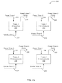
- FIG. 2 a depicts flow diagrams of timers implemented in the redundant bus with fault detection approach of FIG. 1 in accordance with an example implementation.
- FIG. 2 b depicts a flow diagram of the redundant bus with fault detection approach which makes use of the timers of FIG. 2 a in accordance with an example implementation.
- FIG. 2 c depicts a continuation of the flow diagram of FIG. 2 b in accordance with an example implementation.
- FIG. 2 d depicts a continuation of the flow diagram of FIGS. 2 b and 2 c in accordance with an example implementation.
- FIG. 2 e depicts a continuation of the flow diagram of FIG. 2 b - 2 d in accordance with an example implementation.
- FIG. 2 f depicts a continuation of the flow diagram of FIG. 2 b - 2 e in accordance with an example implementation.
- FIG. 1 a block diagram 100 of redundant buses 102 , 104 with fault detection approach that connects a fire alarm central unit (FACU) 106 and remote peripherals 108 , 110 , and 112 in accordance with an example implementation.
- the FACU 106 may have a bus controller, such as a Controller Area Networking (CAN) bus controller 114 and FAIL light emitting diodes (LEDs) 116 .
- the FAIL LEDs 116 indicate if an error or fault has been detected in the FACU 106 or communication buses 102 and 104 .
- the LED is a visual indicator. In other implementations, different or additional visual and audio indicators may be employed.
- the CAN bus controller 114 is a multi-master broadcast serial bus approach for connecting remote peripherals 108 , 110 , and 112 with FACU ( 106 ) and each other. Each remote peripheral 108 , 110 , and 112 , is able to send and receive messages, but not simultaneously.
- a message may consist of an ID (identifier), which represents the priority of the message, and up to eight data bytes. It is transmitted serially onto the bus. This signal pattern may be encoded in non-return-to-zero (NRZ) and is sensed by all nodes.
- ID identifier
- NRZ non-return-to-zero
- the remote peripherals that are connected by a bus are typically sensors, actuators, and other control devices. These devices may not be connected directly to the bus, but through a host processor. If the bus is free, any remote peripheral or controller may begin to transmit. If two or more remote peripherals or controllers begins sending messages at the same time, the message with the more dominant ID (which has more dominant bits, i.e., zeroes) may overwrite other nodes' less dominant IDs, so that eventually (after this arbitration on the ID) only the dominant message remains and is received by all nodes.
- This mechanism is typically referred to as priority based bus arbitration or more specifically Carrier Sense Multiple Access with collision detection. Messages with numerically smaller values of IDs have higher priority and are transmitted first.
- Each remote peripheral may require a host processor that decides what received messages mean and which messages it wants to transmit itself.
- the sensors, actuators, and control devices are typically connected to the host processor.
- the CAN controller may store received bits serially from the bus until an entire message is available, which can then be fetched by the host processor (usually after the CAN controller has triggered an interrupt).
- the host processor stores it's transmit messages to a CAN controller, which transmits the bits serially onto the bus.
- a CAN bus transceiver is able to transmit and receive messages, typically which it receives ⁇ sends from ⁇ to the node's microcontroller.
- the transceiver adapts differential signal levels from the bus to levels that the CAN controller expects and may have protective circuitry that protects the CAN controller.
- the transceiver converts the transmit-bit signal received from the CAN controller into a differential signal that is sent on the bus.
- bit rates up to 1 Mbit/s are possible at network lengths below 40 m. But, by decreasing the bit rate, longer network distances (e.g., 500 m at 125 kbit/s) may be achieved. Note: we limit at about 500 m at 50 kbit/s.
- the CAN data link layer protocol is standardized in ISO 11898-1 (2003). This standard describes mainly the data link layer (composed of the logical link control (LLC) sub-layer and the media access control (MAC) sub-layer) and some aspects of the physical layer of the OSI reference model. All the other protocol layers are typically network or implementation specific.
- the “health” of the bus may be ascertained and ensure that the delivered signal is able to be delivered between the FACU 106 and all remote peripherals 108 , 110 , and 112 .
- four timing parameters may be qualified and inspected by the bus controller (CAN bus controller 114 ). Each of the timing parameters may be unique to an individual system and the time value for each may be tailored to that system or installation.
- the four timing parameters are (1) power up/cold start reset, (2) periodic activity, (3) valid bit time, and (4) maximum pathway delay.
- Timer parameter 1 202 is associated with a power up/cold start time of the controller and is the time period from power up until bus activity occurs.
- a finite time delay exists that a FACU 106 requires before the first activity on the bus is initiated by the CAN bus controller 114 .
- the time is set to a predetermined value of 20 seconds for Timer_ 1 .
- the value for Timer_ 1 may be determined via monitoring the power-up of the FACU 106 or by use of other times that prevent activities during power up initialization of FACU or ( 108 ), ( 110 ), ( 112 ).
- the Timer_ 1 may be preset with a 20 second value 210 and enabled via an enable Timer_ 1 signal 212 .
- a Timer_ 1 expiration signal or message may be triggered 214 . If Timer_ 1 has expired and no activity has occurred on the bus, then the bus may be declared faulty. If redundant buses are present, and the other bus is not faulting, then messaging may be routed over the non-faulting bus.
- Timer_ 2 204 may be preset 216 to 110 milliseconds in the example. This time may be set for a margin of error just above the maximum typically expected CAN redundant bus traffic within a given implementation.
- the FACU “pings” all its nodes to check for a response periodically. If a node does not acknowledge its address specific “ping,” the FACU knows there is a problem with that peripheral. If the embodiment detects that the typically periodic ping time is exceeded, it knows that a fault condition exists and handles accordingly.
- the 110 milliseconds (mS) may be determined to be a threshold that some bus activity from a remote peripheral should occur or that the FACU has an error in not sending out the typically periodic “ping”.
- a Timer_ 2 expiration signal may be generated 220 .
- the value of 110 mS is set as a constant upper threshold of silence on the bus in the current example, but in other implementations the value may be different and be determined by typical system traffic parameters in the redundant bus implementation.
- a controller may keep track of the maximum time between reception of a message from a peripheral device that is less than a hard coded maximum and preset Timer_ 2 216 with that value.
- the third timer timer_ 3 206 is a valid bit timer and is associated with the typical single “bit” time of the installed redundant CAN bus system.
- the valid bit timer is used to verify that the “bit” time is not too short (e.g. for 50 Kbits/sec a bit time is approx 20 ⁇ Sec); so if Timer_ 3 expires true, a condition of error in the form of a concatenated bit time was not experienced.
- Each of the redundant buses is typically set at one speed in bits per second and remains at that speed. The speed is inversely proportional to the bit time, and may actually be 1/bit time.
- a transmission speed of fifty Kilobits per second is universally deployed in product offerings. This results in an individual bit time of twenty microseconds (20 ⁇ Sec; or 20 ⁇ 10 ⁇ 6 seconds).
- the CAN bus controller monitors each bit time and insures that it exceeds the minimum threshold of fifteen microseconds (15 ⁇ Sec; or 15 ⁇ 10 ⁇ 6 seconds).
- logic transitions may occur however they will be short “spikes” far below the valid bit time in duration.
- the CAN bus controller may detect this fault, annunciate it, and ensure the connection of a valid functioning pathway between the Cabinet and Remote Circuit Node(s). Therefore in the current example, a predetermined value of 15 mS may be used as a constant lower limit threshold; but this value may be a user configured value in other implementations. Or in yet other implementations, the value may be a “constants” loaded by the CAN bus controller at power up.
- the value of Timer_ 3 may be preset 222 (15 mS in the current example) and enabled by signal 224 . Upon expiration of Timer_ 3 , a Timer_ 3 expire signal may be generated 226 .
- the fourth timer Timer_ 4 208 is associated with the cable propagation delay and is the maximum pathway delay.
- the maximum possible pathway differential between the redundant pathways may be given a propagation delay of approximately 5 nanoseconds per meter; the typical worst case delay between the pathway upon which the “1 st bit even” is experienced and the subsequent “longer length” pathway.
- the CAN bus controller may initially select the first valid bus by way of first activity.
- the first valid bus provides connectivity between the cabinet and Remote Nodes on that specific bus. As there typically will be a maximum bus cable length and a maximum delay time per unit length of cable (e.g.
- the CAN bus controller may ascertain a maximum expected delay time for bus activity to appear on the “longer” bus pathway.
- a maximum cable length of 300 meters is projected for one of the redundant buses and assuming a maximum transmission line propagation delay of 5 nS per meter, and adding in the propagation delay for a typical bus physical layer transceiver, a value of two microseconds (2 ⁇ Sec or 2 ⁇ 10 ⁇ 6 Seconds) may be determined as the maximum “lag” time that the longer bus pathway should exhibit compared with the first detected shorter bus pathway. Therefore, a value of two microseconds (2 ⁇ Sec) may be used as a constant upper limit threshold.
- this value may be a user configured value for different systems.
- a value for this timer may be treated like other “constants” loaded by a master microcontroller at power up that could ascertain the correct applicable “constant” value.
- the value of Timer_ 4 the maximum pathway delay, may be preset 228 (2 mS in the current example) and enabled by signal 230 . Upon expiration of timer_ 4 , a Timer expire signal may be generated 232 .
- the timers of FIG. 2 a are initialized with their preset values. All CAN bus pathway FAIL LEDs may be extinguished 252 . Redundant bus 1 (CAN bus pathway 1 ) peripherals may be enabled while redundant bus 2 (CAN bus pathway 2 ) peripherals may be disabled 254 .
- the cold start timer “Timer_ 1 ” 202 is also enabled 256 .
- the terms “disabled” means to make the CAN bus pathway as a background secondary or non-primary pathway (if there are no faults present). The term “enable” means to make the CAN bus pathway the primary pathway.
- FIG. 2 c a continuation of the flow diagram of FIG. 2 b in accordance with an example implementation is depicted. If in FIG. 2 b , a bit is detected on CAN bus pathway 2 , then Timer_ 1 is reset 292 and CAN bus pathway 1 is disabled and CAN bus pathway 2 is enabled 294 . Timer_ 2 , Timer_ 3 and Timer_ 4 are also enabled at this time 296 and the flow continues to FIG. 2 d.
- FIG. 2 d a continuation of the flow diagram of FIGS. 2 b and 2 c in accordance with an example implementation is depicted.
- timers Timer_ 2 , Timer_ 3 , and Timer_ 4
- a determination is made if another bit is detected on CAN bus pathway 2 308 . If a bit is detected on CAN bus pathway 2 308 , then Timer_ 2 is reset 302 .
- a check is then made if Timer_ 3 has expired 306 . If Timer_ 3 has expired, then Timer_ 3 is reset 304 and one of the two inputs into AND function 300 is set. If Timer_ 3 has not expired 306 , then Timer_ 3 is reset 314 and one of two inputs to “OR” function 316 is set.
- CAN bus pathway 1 has activity 320 , where “1->0 or 0->1” means either a bit transition of dominant to recessive or recessive to dominant activity. If there is activity on CAN pathway 1 320 , then the CAN bus pathway 1 FAIL LED is extinguished 322 and an input to “OR” function 324 may be set. If there is no activity on CAN bus pathway 1 , 320 and Timer_ 4 has expired, then CAN bus pathway 1 FAIL LED is illuminated 328 and a second input to the “OR” function 324 may be set.
- CAN bus pathway 2 is again checked for RxD 1->0. If Timer_ 2 has expired 310 , then Timer_ 3 is reset 312 and a second condition to “OR” function 316 is set. If either condition of “OR” function 316 is set, then CAN bus pathway 2 FAIL LED is illuminate. If both condition of “AND” function 300 are set, then Timer_ 2 is enabled 284 FIG. 2 c and a determination is made if a bit is detected on CAN bus pathway 2 280 .
- Timer_ 2 is reset 286 and the CAN bus pathway 2 FAIL LED is extinguished 288 .
- Timers Timer_ 2 , Timer_ 3 , and Timer_ 4 may then be enabled 296 and processing continues in FIG. 2 d . Otherwise if CAN bus pathway 2 bit is not detected 280 and Timer_ 2 is expired 282 , then CAN bus pathway 2 FAIL LED is illuminated 290 and Timer_ 2 is reset 298 and processing continues at 362 , FIG. 2 e . If Timer_ 2 has not expired 282 , then CAN bus pathway 2 is checked again for a bit 280 .
- Timer_ 1 is reset 360 after a bit has been detected on CAN bus pathway 1 258 FIG. 2 b .
- the CAN bus pathway is enabled and CAN bus pathway 2 is disabled 362 .
- Timer_ 2 , Timer_ 3 , and Timer_ 4 are enabled 364 and checks are made for activity on CAN bus pathway 2 372 . If CAN bus pathway 2 has activity, then CAN bus pathway 2 FAIL LED is extinguished 374 and a condition is set for “OR” function 380 .
- CAN bus pathway 2 activity is not detected 372 a check is made if Timer_ 4 has expired 376 . If Timer_ 4 has not expired 376 , then CAN bus pathway 2 is checked for activity again 372 . Otherwise if Timer_ 4 has expired 376 , then CAN bus pathway 2 FAIL LED is illuminated 378 and the second condition is set on “OR” function 380 .
- FIG. 2 f a continuation of the flow diagram of FIG. 2 b - 2 e in accordance with an example implementation is depicted.
- a check is made on CAN bus pathway 1 to determine if a bit has been detected 400 . If a bit has been detected on CAN bus pathway 1 , Timer_ 2 is reset 402 and a check is made if Timer_ 3 has expired 408 . If Timer_ 3 has expired 408 , then Timer_ 3 is reset 410 and the first condition of the “AND” function 412 is set. If Timer_ 3 has not expired 408 , then Timer_ 3 is reset 414 and the first condition of the “OR” function 418 is set.
- Timer_ 2 has expired 406 . If Timer_ 2 has not expired 406 , then the CAN bus pathway 1 is checked again 400 . If Timer_ 2 has expired 406 , then Timer_ 2 is reset 416 and the second condition of an “OR” function 418 is set. If either condition of “OR” function 418 is set, then CAN bus pathway 1 FAIL LED is illuminated 419 .
- Timer_ 4 420 FIG. 2 f is reset and the second condition of “AND” function 412 is set. If both conditions of the “AND” function 410 are set, then Timer_ 2 is enabled 358 FIG. 2 e and a determination if a bit has been detected on CAN bus pathway 1 is made 352 .
- Timer_ 2 is reset 368 and the CAN bus pathway 1 FAIL LED is extinguished 370 and Timer_ 2 , Timer_ 3 , and Timer_ 4 are enabled 364 . If a bit is not detected on CAN bus pathway 1 352 , then a check of expiration of Timer_ 2 is made 354 . If Timer_ 2 has not expired 354 , then the CAN bus pathway 1 is again checked for a bit 352 . Otherwise, if Timer_ 2 has expired, 354 CAN bus pathway 1 FAIL LED is illuminated 356 and Timer_ 2 is reset 350 .
- Timer_ 2 is reset 350 , then CAN bus pathway 2 is enabled and CAN bus pathway 1 is disabled 294 FIG. 2 c . Similarly if CAN bus pathway 1 FAIL LED is illuminated 419 , then CAN bus pathway 2 is enabled and CAN bus pathway 1 is disabled 294 .
- the immediate annunciation of a fault detection and continuous monitoring of bus health of the redundant CAN bus pathways inherently provides additional information to managers of Building Technology safety logistics. Additional information in the immediate detection of faults such as accidently cut wire paths (i.e. miscellaneous construction activity such as drilling through a sheet rock wall) may be identified and rectified before time of emergency. A simple cold start “power up” system check may be routinely performed to verify the health of BOTH CAN bus pathways and provide managers of Building Technology safety the ease of mind from the additional information that the redundant CAN bus pathways are both fully operational BEFORE an emergency condition occurs. The system also provides the FACU additional information which in turn may be provided to Building Technologies safety management personnel.
- the FACU may quickly sequentially ping the nodes from nearest to most distant and identify the exact geographical location area of the fault by observing the last successful response to a ping and the first failed response. This additional information precludes the need of physically examining the entire circuit pathway to identify the exact location of the short or open circuit condition.
- additional information in the form of knowing the regional geographic core of a possible emergency (i.e. fire within a wall(s) which has not yet caused a smoke detector to trip) and this additional information allows Building Technology safety management personnel to more efficiently evacuate personnel and ⁇ or valuable property.
Abstract
Description
-
- All circuits have a redundant path.
- Circuit paths between the Fire Alarm Central Unit (FACU) and remote peripherals shall continue to operate flawlessly under the condition of a single open or a single short circuit condition.
- Circuit paths shall be monitored and supervised to detect and annunciate a short or open circuit condition.
Thus, FACU and remote peripherals must be monitored and any short or open circuit conditions must be annunciated in order to fulfill the requirements of the “class X” performance criteria.
Claims (12)
Priority Applications (3)
| Application Number | Priority Date | Filing Date | Title |
|---|---|---|---|
| US13/833,021 US9244753B2 (en) | 2013-03-15 | 2013-03-15 | Redundant bus fault detection |
| PCT/US2014/027917 WO2014143798A2 (en) | 2013-03-15 | 2014-03-14 | Redundant bus fault detection |
| CA2906144A CA2906144C (en) | 2013-03-15 | 2014-03-14 | Redundant bus fault detection |
Applications Claiming Priority (1)
| Application Number | Priority Date | Filing Date | Title |
|---|---|---|---|
| US13/833,021 US9244753B2 (en) | 2013-03-15 | 2013-03-15 | Redundant bus fault detection |
Publications (2)
| Publication Number | Publication Date |
|---|---|
| US20140281752A1 US20140281752A1 (en) | 2014-09-18 |
| US9244753B2 true US9244753B2 (en) | 2016-01-26 |
Family
ID=50513488
Family Applications (1)
| Application Number | Title | Priority Date | Filing Date |
|---|---|---|---|
| US13/833,021 Active 2034-07-24 US9244753B2 (en) | 2013-03-15 | 2013-03-15 | Redundant bus fault detection |
Country Status (3)
| Country | Link |
|---|---|
| US (1) | US9244753B2 (en) |
| CA (1) | CA2906144C (en) |
| WO (1) | WO2014143798A2 (en) |
Families Citing this family (4)
| Publication number | Priority date | Publication date | Assignee | Title |
|---|---|---|---|---|
| US9244753B2 (en) * | 2013-03-15 | 2016-01-26 | Siemens Schweiz Ag | Redundant bus fault detection |
| KR20150086894A (en) * | 2014-01-21 | 2015-07-29 | 한국전자통신연구원 | Apparatus and method for controlling transmission power in can communication |
| CN110532209B (en) * | 2019-08-13 | 2022-02-22 | 南京芯驰半导体科技有限公司 | Safety bus system based on redundancy heterogeneous |
| CN111614532B (en) * | 2020-05-13 | 2022-04-12 | 湖北三江航天万峰科技发展有限公司 | CAN redundant communication system based on DSP |
Citations (37)
| Publication number | Priority date | Publication date | Assignee | Title |
|---|---|---|---|---|
| US4259548A (en) * | 1979-11-14 | 1981-03-31 | Gte Products Corporation | Apparatus for monitoring and signalling system |
| US4689619A (en) * | 1985-12-26 | 1987-08-25 | General Instrument Corporation | Method and apparatus for polling subscriber terminals |
| US5390326A (en) | 1993-04-30 | 1995-02-14 | The Foxboro Company | Local area network with fault detection and recovery |
| US6084521A (en) * | 1998-04-13 | 2000-07-04 | Pittway Corporation | Waterflow detector with electronic timer |
| US6195018B1 (en) * | 1996-02-07 | 2001-02-27 | Cellnet Data Systems, Inc. | Metering system |
| US6275160B1 (en) * | 1998-04-13 | 2001-08-14 | Pittway Corporation | Multi-mode waterflow detector with electronic timer |
| US20010023392A1 (en) * | 2000-03-17 | 2001-09-20 | Norihiro Nakatsuhama | Abnormality detection device for detecting an abnormality in a communication bus |
| US20010049759A1 (en) * | 1996-09-20 | 2001-12-06 | Hiroki Miura | Bus controlling method and apparatus for delaying activation of a bus cycle |
| US20020064185A1 (en) * | 2000-11-27 | 2002-05-30 | Satoru Nakai | Synchronizing system using IEEE1394 serial bus standard |
| US20020087763A1 (en) * | 1999-05-12 | 2002-07-04 | Wendorff Wilhard Von | Communication sytem with a communication bus |
| US20020152411A1 (en) * | 2001-04-13 | 2002-10-17 | Olsen Ronald D. | Timing multiple events with a single timer |
| US20030028687A1 (en) * | 1999-08-23 | 2003-02-06 | Emray Rein Goossen | Scalable data collection and computing apparatus |
| US20040176877A1 (en) | 2003-03-05 | 2004-09-09 | Scott Hesse | Building automation system and method |
| US20040230878A1 (en) * | 2003-05-14 | 2004-11-18 | Mantey Paul John | Detecting and diagnosing a malfunctioning host coupled to a communications bus |
| US20050015521A1 (en) * | 2001-09-13 | 2005-01-20 | Florian Hartwich | Method and device for producing program interruptions in subscribers to a bus system, and corresponding bus systems |
| US20050066062A1 (en) * | 2001-09-13 | 2005-03-24 | Florian Hartwich | Method and device for determining time in a bus system and corresponding bus system |
| US20050076270A1 (en) * | 2001-11-14 | 2005-04-07 | Hans-Geroge Bogenrieder | Method and device for checking the error-free function of modules in bus system comprising a central unit |
| US20050180362A1 (en) * | 2004-02-18 | 2005-08-18 | Tom Chin | Method for reduced access delay in multiple access attempt exchanges |
| US20060174042A1 (en) * | 2003-06-18 | 2006-08-03 | Andreas Weigl | Method, device and system for the exchange of data via a bus system |
| US20060233193A1 (en) * | 2003-05-20 | 2006-10-19 | Koninklijke Philips Electronics N.V. | Time-triggered communication system and method for the synchronized start of a dual-channel network |
| US20070174344A1 (en) * | 2005-12-28 | 2007-07-26 | Goh Chee H | Rate control of flow control updates |
| EP1901145A2 (en) | 2006-08-23 | 2008-03-19 | MicroNet Sensorik GmbH | Field device and method of operating the same |
| US20080170475A1 (en) * | 2007-01-12 | 2008-07-17 | Simon Gregory R | 20-second/100-second lacrosse timer |
| US20080276107A1 (en) * | 2004-05-03 | 2008-11-06 | Freescale Semiconductor, Inc. | Method and Device to Wake-Up Nodes in a Serial Data Bus |
| US20080273527A1 (en) * | 2007-05-03 | 2008-11-06 | The University Of Leicester | Distributed system |
| US20080307132A1 (en) * | 2007-06-05 | 2008-12-11 | Artur Zaks | Expanded Memory for Communications Controller |
| US20090001892A1 (en) * | 2006-01-30 | 2009-01-01 | Koninklijke Philips Electronics N.V. | Lighting Control System |
| US20090240857A1 (en) * | 2004-06-26 | 2009-09-24 | Florian Hartwich | Method and device for controlling a bus system and a corresponding bus system |
| US20090276666A1 (en) | 2008-04-30 | 2009-11-05 | Egenera, Inc. | System, method, and adapter for creating fault-tolerant communication busses from standard components |
| US20100020810A1 (en) * | 2008-07-23 | 2010-01-28 | International Business Machines Corporation | Link Services in a Communication Network |
| US20100253531A1 (en) * | 2009-04-02 | 2010-10-07 | Rongbin Qiu | System and method of controlling indicators of a property monitoring system |
| US8332693B2 (en) * | 2007-11-30 | 2012-12-11 | Huawei Technologies Co., Ltd. | Method and apparatus for failure notification |
| US20130027198A1 (en) * | 2011-07-28 | 2013-01-31 | Piccolo Iii Joseph | Method and apparatus for communicating with non-addressable notification appliances |
| US8487739B2 (en) * | 2008-12-22 | 2013-07-16 | Zenith Electronics Llc | Television theft deterrence |
| US20140103955A1 (en) * | 2012-10-11 | 2014-04-17 | Hamilton Sundstrand Corporation | System and method for automated failure detection of hold-up power storage devices |
| US20140281752A1 (en) * | 2013-03-15 | 2014-09-18 | Siemens Aktiengesellschaft | Redundant bus fault detection |
| US8977794B2 (en) * | 2008-10-27 | 2015-03-10 | Lennox Industries, Inc. | Communication protocol system and method for a distributed-architecture heating, ventilation and air conditioning network |
-
2013
- 2013-03-15 US US13/833,021 patent/US9244753B2/en active Active
-
2014
- 2014-03-14 CA CA2906144A patent/CA2906144C/en active Active
- 2014-03-14 WO PCT/US2014/027917 patent/WO2014143798A2/en active Application Filing
Patent Citations (37)
| Publication number | Priority date | Publication date | Assignee | Title |
|---|---|---|---|---|
| US4259548A (en) * | 1979-11-14 | 1981-03-31 | Gte Products Corporation | Apparatus for monitoring and signalling system |
| US4689619A (en) * | 1985-12-26 | 1987-08-25 | General Instrument Corporation | Method and apparatus for polling subscriber terminals |
| US5390326A (en) | 1993-04-30 | 1995-02-14 | The Foxboro Company | Local area network with fault detection and recovery |
| US6195018B1 (en) * | 1996-02-07 | 2001-02-27 | Cellnet Data Systems, Inc. | Metering system |
| US20010049759A1 (en) * | 1996-09-20 | 2001-12-06 | Hiroki Miura | Bus controlling method and apparatus for delaying activation of a bus cycle |
| US6084521A (en) * | 1998-04-13 | 2000-07-04 | Pittway Corporation | Waterflow detector with electronic timer |
| US6275160B1 (en) * | 1998-04-13 | 2001-08-14 | Pittway Corporation | Multi-mode waterflow detector with electronic timer |
| US20020087763A1 (en) * | 1999-05-12 | 2002-07-04 | Wendorff Wilhard Von | Communication sytem with a communication bus |
| US20030028687A1 (en) * | 1999-08-23 | 2003-02-06 | Emray Rein Goossen | Scalable data collection and computing apparatus |
| US20010023392A1 (en) * | 2000-03-17 | 2001-09-20 | Norihiro Nakatsuhama | Abnormality detection device for detecting an abnormality in a communication bus |
| US20020064185A1 (en) * | 2000-11-27 | 2002-05-30 | Satoru Nakai | Synchronizing system using IEEE1394 serial bus standard |
| US20020152411A1 (en) * | 2001-04-13 | 2002-10-17 | Olsen Ronald D. | Timing multiple events with a single timer |
| US20050015521A1 (en) * | 2001-09-13 | 2005-01-20 | Florian Hartwich | Method and device for producing program interruptions in subscribers to a bus system, and corresponding bus systems |
| US20050066062A1 (en) * | 2001-09-13 | 2005-03-24 | Florian Hartwich | Method and device for determining time in a bus system and corresponding bus system |
| US20050076270A1 (en) * | 2001-11-14 | 2005-04-07 | Hans-Geroge Bogenrieder | Method and device for checking the error-free function of modules in bus system comprising a central unit |
| US20040176877A1 (en) | 2003-03-05 | 2004-09-09 | Scott Hesse | Building automation system and method |
| US20040230878A1 (en) * | 2003-05-14 | 2004-11-18 | Mantey Paul John | Detecting and diagnosing a malfunctioning host coupled to a communications bus |
| US20060233193A1 (en) * | 2003-05-20 | 2006-10-19 | Koninklijke Philips Electronics N.V. | Time-triggered communication system and method for the synchronized start of a dual-channel network |
| US20060174042A1 (en) * | 2003-06-18 | 2006-08-03 | Andreas Weigl | Method, device and system for the exchange of data via a bus system |
| US20050180362A1 (en) * | 2004-02-18 | 2005-08-18 | Tom Chin | Method for reduced access delay in multiple access attempt exchanges |
| US20080276107A1 (en) * | 2004-05-03 | 2008-11-06 | Freescale Semiconductor, Inc. | Method and Device to Wake-Up Nodes in a Serial Data Bus |
| US20090240857A1 (en) * | 2004-06-26 | 2009-09-24 | Florian Hartwich | Method and device for controlling a bus system and a corresponding bus system |
| US20070174344A1 (en) * | 2005-12-28 | 2007-07-26 | Goh Chee H | Rate control of flow control updates |
| US20090001892A1 (en) * | 2006-01-30 | 2009-01-01 | Koninklijke Philips Electronics N.V. | Lighting Control System |
| EP1901145A2 (en) | 2006-08-23 | 2008-03-19 | MicroNet Sensorik GmbH | Field device and method of operating the same |
| US20080170475A1 (en) * | 2007-01-12 | 2008-07-17 | Simon Gregory R | 20-second/100-second lacrosse timer |
| US20080273527A1 (en) * | 2007-05-03 | 2008-11-06 | The University Of Leicester | Distributed system |
| US20080307132A1 (en) * | 2007-06-05 | 2008-12-11 | Artur Zaks | Expanded Memory for Communications Controller |
| US8332693B2 (en) * | 2007-11-30 | 2012-12-11 | Huawei Technologies Co., Ltd. | Method and apparatus for failure notification |
| US20090276666A1 (en) | 2008-04-30 | 2009-11-05 | Egenera, Inc. | System, method, and adapter for creating fault-tolerant communication busses from standard components |
| US20100020810A1 (en) * | 2008-07-23 | 2010-01-28 | International Business Machines Corporation | Link Services in a Communication Network |
| US8977794B2 (en) * | 2008-10-27 | 2015-03-10 | Lennox Industries, Inc. | Communication protocol system and method for a distributed-architecture heating, ventilation and air conditioning network |
| US8487739B2 (en) * | 2008-12-22 | 2013-07-16 | Zenith Electronics Llc | Television theft deterrence |
| US20100253531A1 (en) * | 2009-04-02 | 2010-10-07 | Rongbin Qiu | System and method of controlling indicators of a property monitoring system |
| US20130027198A1 (en) * | 2011-07-28 | 2013-01-31 | Piccolo Iii Joseph | Method and apparatus for communicating with non-addressable notification appliances |
| US20140103955A1 (en) * | 2012-10-11 | 2014-04-17 | Hamilton Sundstrand Corporation | System and method for automated failure detection of hold-up power storage devices |
| US20140281752A1 (en) * | 2013-03-15 | 2014-09-18 | Siemens Aktiengesellschaft | Redundant bus fault detection |
Non-Patent Citations (2)
| Title |
|---|
| Failure Detection in a Symmetric System, IBM Technical Disclosure Bulletin, International Business Machines Corp. (Thornwood), US, vol. 38, No. 1, Jan. 1, 1995, pp. 173-175, XP000498729. (4 pages). |
| PCT Search Report dated Jul. 4, 2014, for Application No. PCT/US2014/027917. (8 pages). |
Also Published As
| Publication number | Publication date |
|---|---|
| CA2906144C (en) | 2018-10-30 |
| US20140281752A1 (en) | 2014-09-18 |
| WO2014143798A2 (en) | 2014-09-18 |
| CA2906144A1 (en) | 2014-09-18 |
| WO2014143798A3 (en) | 2014-11-13 |
Similar Documents
| Publication | Publication Date | Title |
|---|---|---|
| Lee et al. | Network-based fire-detection system via controller area network for smart home automation | |
| US7222256B2 (en) | System and method for controlling redundant communication links in networked safety systems | |
| US6442708B1 (en) | Fault localization and health indication for a controller area network | |
| CA2906144C (en) | Redundant bus fault detection | |
| US9497038B2 (en) | Self-healing communications network | |
| JP7280082B2 (en) | Fraud detection method, fraud detection device and program | |
| US9257032B2 (en) | System and method for emergency communication in a TCP/IP based redundant fire panel network | |
| US10063416B2 (en) | Bidirectional redundant mesh networks | |
| WO2007121162A1 (en) | Alarm system sensor topology apparatus and method | |
| CN109102686B (en) | System and method for preventing false alarms during alarm sensitivity threshold changes in fire alarm systems | |
| EP2801961B1 (en) | System and method for using customer data networks for alarm systems | |
| CN105490837A (en) | Network monitoring processing method and device | |
| WO2017108372A1 (en) | Power-over-ethernet lighting system | |
| JP4968169B2 (en) | Communication system and communication method | |
| EP2078234B1 (en) | System and method facilitating double address detection | |
| KR101214299B1 (en) | R type fire alarm control panel system capable of verifying false alarm and method thereof | |
| JP2009089111A (en) | Monitoring server, monitoring system, and communication method in monitoring system | |
| JP7213100B2 (en) | Electronics | |
| JP2005242614A (en) | Fire alarm system | |
| Neugschwandtner et al. | Fire safety alarm transmission in networked building automation systems | |
| Lee et al. | Development of CAN based Automatic Fire Detection System | |
| JPS59136893A (en) | Premise disaster prevention system |
Legal Events
| Date | Code | Title | Description |
|---|---|---|---|
| AS | Assignment |
Owner name: SIEMENS INDUSTRY INC., GEORGIA Free format text: ASSIGNMENT OF ASSIGNORS INTEREST;ASSIGNORS:KEATING, MICHAEL J.;STRELECKI, PAUL RICHARD;BARONCINI, VINCENT;AND OTHERS;SIGNING DATES FROM 20130313 TO 20130802;REEL/FRAME:037198/0854 Owner name: SIEMENS INDUSTRY INC., GEORGIA Free format text: ASSIGNMENT OF ASSIGNORS INTEREST;ASSIGNOR:SCHERMANN, HARALD;REEL/FRAME:037199/0110 Effective date: 20130314 |
|
| AS | Assignment |
Owner name: SIEMENS SCHWEIZ AG, SWITZERLAND Free format text: ASSIGNMENT OF ASSIGNORS INTEREST;ASSIGNOR:SIEMENS INDUSTRY, INC.;REEL/FRAME:037292/0895 Effective date: 20130802 Owner name: SIEMENS SCHWEIZ AG, SWITZERLAND Free format text: ASSIGNMENT OF ASSIGNORS INTEREST;ASSIGNOR:SIEMENS AKTIENGESELLSCHAFT;REEL/FRAME:037293/0376 Effective date: 20151209 Owner name: SIEMENS AKTIENGESELLSCHAFT, GERMANY Free format text: ASSIGNMENT OF ASSIGNORS INTEREST;ASSIGNOR:SIEMENS SCHWEIZ AG;REEL/FRAME:037293/0308 Effective date: 20140303 |
|
| STCF | Information on status: patent grant |
Free format text: PATENTED CASE |
|
| MAFP | Maintenance fee payment |
Free format text: PAYMENT OF MAINTENANCE FEE, 4TH YEAR, LARGE ENTITY (ORIGINAL EVENT CODE: M1551); ENTITY STATUS OF PATENT OWNER: LARGE ENTITY Year of fee payment: 4 |
|
| MAFP | Maintenance fee payment |
Free format text: PAYMENT OF MAINTENANCE FEE, 8TH YEAR, LARGE ENTITY (ORIGINAL EVENT CODE: M1552); ENTITY STATUS OF PATENT OWNER: LARGE ENTITY Year of fee payment: 8 |