US9722665B2 - Communication nodes and sensor devices configured to use power line communication signals, and related methods of operation - Google Patents

Communication nodes and sensor devices configured to use power line communication signals, and related methods of operation Download PDF

Info

Publication number
US9722665B2
US9722665B2 US14/270,914 US201414270914A US9722665B2 US 9722665 B2 US9722665 B2 US 9722665B2 US 201414270914 A US201414270914 A US 201414270914A US 9722665 B2 US9722665 B2 US 9722665B2
Authority
US
United States
Prior art keywords
power line
communication node
electric grid
communication signal
line communication
Prior art date
Legal status (The legal status is an assumption and is not a legal conclusion. Google has not performed a legal analysis and makes no representation as to the accuracy of the status listed.)
Active, expires
Application number
US14/270,914
Other versions
US20150180282A1 (en
Inventor
Raiford Smith
Stuart Laval
Jason Handley
Current Assignee (The listed assignees may be inaccurate. Google has not performed a legal analysis and makes no representation or warranty as to the accuracy of the list.)
Duke Energy Corp
Original Assignee
Duke Energy Corp
Priority date (The priority date is an assumption and is not a legal conclusion. Google has not performed a legal analysis and makes no representation as to the accuracy of the date listed.)
Filing date
Publication date
Application filed by Duke Energy Corp filed Critical Duke Energy Corp
Priority to US14/270,914 priority Critical patent/US9722665B2/en
Assigned to DUKE ENERGY CORPORATION reassignment DUKE ENERGY CORPORATION ASSIGNMENT OF ASSIGNORS INTEREST (SEE DOCUMENT FOR DETAILS). Assignors: HANDLEY, JASON, LAVAL, STUART, SMITH, RAIFORD
Assigned to DUKE ENERGY CORPORATION reassignment DUKE ENERGY CORPORATION CORRECTIVE ASSIGNMENT TO CORRECT THE ASSIGNMENT DOCUMENT ?WHEREAS, DUKE ENERGY CORPORATION, A NORTH CAROLINA CORPORATION?? PREVIOUSLY RECORDED ON REEL 032832 FRAME 0452. ASSIGNOR(S) HEREBY CONFIRMS THE ASSIGNMENT DOCUMENT HAS BEEN CORRECTED TO READ -- WHEREAS, DUKE ENERGY CORPORATION, A DELAWARE CORPORATION?? --. Assignors: HANDLEY, JASON, LAVAL, STUART, SMITH, RAIFORD
Publication of US20150180282A1 publication Critical patent/US20150180282A1/en
Application granted granted Critical
Publication of US9722665B2 publication Critical patent/US9722665B2/en
Active legal-status Critical Current
Adjusted expiration legal-status Critical

Links

Images

Classifications

    • HELECTRICITY
    • H04ELECTRIC COMMUNICATION TECHNIQUE
    • H04BTRANSMISSION
    • H04B3/00Line transmission systems
    • H04B3/54Systems for transmission via power distribution lines
    • HELECTRICITY
    • H04ELECTRIC COMMUNICATION TECHNIQUE
    • H04QSELECTING
    • H04Q9/00Arrangements in telecontrol or telemetry systems for selectively calling a substation from a main station, in which substation desired apparatus is selected for applying a control signal thereto or for obtaining measured values therefrom
    • HELECTRICITY
    • H04ELECTRIC COMMUNICATION TECHNIQUE
    • H04JMULTIPLEX COMMUNICATION
    • H04J13/00Code division multiplex systems
    • HELECTRICITY
    • H04ELECTRIC COMMUNICATION TECHNIQUE
    • H04LTRANSMISSION OF DIGITAL INFORMATION, e.g. TELEGRAPHIC COMMUNICATION
    • H04L25/00Baseband systems
    • H04L25/02Details ; arrangements for supplying electrical power along data transmission lines
    • H04L25/026Arrangements for coupling transmitters, receivers or transceivers to transmission lines; Line drivers
    • HELECTRICITY
    • H04ELECTRIC COMMUNICATION TECHNIQUE
    • H04LTRANSMISSION OF DIGITAL INFORMATION, e.g. TELEGRAPHIC COMMUNICATION
    • H04L25/00Baseband systems
    • H04L25/02Details ; arrangements for supplying electrical power along data transmission lines
    • H04L25/0264Arrangements for coupling to transmission lines
    • H04L25/0272Arrangements for coupling to multiple lines, e.g. for differential transmission
    • HELECTRICITY
    • H04ELECTRIC COMMUNICATION TECHNIQUE
    • H04QSELECTING
    • H04Q2209/00Arrangements in telecontrol or telemetry systems
    • H04Q2209/30Arrangements in telecontrol or telemetry systems using a wired architecture

Definitions

  • the present disclosure relates to utility grids.
  • An electric grid may include various electric grid devices, which may be intelligent, interconnected equipment that deliver, monitor, measure, and/or control the flow of electricity in a power delivery system.
  • the electric grid may also include a telecommunications infrastructure for transporting and delivering information regarding the electric grid, as well as analytics, architecture, and data-management tools for managing/optimizing the electric grid.
  • a wide variety of electric grid customer-owned assets which may consume, store, or produce electricity, may be connected to the electric grid.
  • an electric grid As an electric grid, and various interconnected customer-owned devices and electric grid devices in the electric grid, become more complex, it may be more difficult to meet electric utility customers' demands regarding response times, costs, safety, and reliability.
  • an electric grid may reach diverse geographies, customers, and vendor technologies. Accordingly, processing data and managing electric grid devices may be costly and time-consuming.
  • Various embodiments of the present inventive concepts include a method of operating a communication node.
  • the method may include transmitting a first power line communication signal from the communication node to a sensor device that is at or adjacent an electric grid device.
  • the method may include receiving from the sensor device a second power line communication signal that is responsive to the first power line communication signal, at the communication node.
  • the method may include determining a distance between the communication node and the electric grid device by measuring an electrical parameter of the second power line communication signal, at the communication node.
  • transmitting the first power line communication signal may include transmitting the first power line communication signal using a Mid Voltage (MV) electric distribution network corresponding to voltages between about 4,000 Volts and about 69,000 Volts.
  • receiving the second power line communication signal may include receiving the second power line communication signal using the Mid Voltage (MV) electric distribution network corresponding to voltages between about 4,000 Volts and about 69,000 Volts.
  • the first power line communication signal may include a Power Line Carrier (PLC) signal or a Broadband over Power Lines (BPL) signal.
  • PLC Power Line Carrier
  • BPL Broadband over Power Lines
  • the method may include transmitting, from the communication node to an electric utility head end system or a higher-tier communication node, a value representing the distance, via a local area network or a Wide Area Network (e.g., a cellular network, Ethernet, or a fiber network). Additionally or alternatively, determining the distance between the communication node and the electric grid device by measuring the electrical parameter of second power line communication signal at the communication node may include determining the distance between the communication node and the electric grid device by measuring an impedance corresponding to the second power line communication signal, at the communication node.
  • a local area network or a Wide Area Network e.g., a cellular network, Ethernet, or a fiber network.
  • the method may include determining a device type of the electric grid device by analyzing an identification component (e.g., a frequency identification component or another identification component) of the second power line communication signal, at the communication node. Additionally or alternatively, the method may include determining whether the electric grid device is electrically connected to an electric grid, by analyzing an identification component of the second power line communication signal, at the communication node. Moreover, in some embodiments, the method may include monitoring a health component of the electric grid device by analyzing an electrical signature and/or an electrical parameter of the second power line communication signal, at the communication node.
  • an identification component e.g., a frequency identification component or another identification component
  • the sensor device may be a first sensor device, and the electric grid device may be a first electric grid device.
  • transmitting the first power line communication signal may include transmitting an unsolicited ping from the communication node to the first sensor device and to a second sensor device that is at or adjacent a second electric grid device.
  • the distance may be a first distance
  • the electrical parameter may be a first electrical parameter.
  • the method may include receiving from the second sensor device a third power line communication signal that is responsive to the unsolicited ping, at the communication node, and determining a second distance between the communication node and the second electric grid device by measuring a second electrical parameter of the third power line communication signal, at the communication node.
  • a communication node may include a power line communications interface configured to transmit a first power line communication signal from the communication node to a sensor device that is at or adjacent an electric grid device, and to receive from the sensor device a second power line communication signal that is responsive to the first power line communication signal.
  • the communication node may include a processor configured to determine a distance between the communication node and the electric grid device by measuring an electrical parameter of the second power line communication signal at the communication node.
  • the communication node may include a polling device that includes at least one of the power line communications interface and the processor.
  • the power line communications interface may be configured to transmit the first power line communication signal using a Mid Voltage (MV) electric distribution network corresponding to voltages between about 4,000 Volts and about 69,000 Volts, and to receive the second power line communication signal using the Mid Voltage (MV) electric distribution network corresponding to voltages between about 4,000 Volts and about 69,000 Volts.
  • the first power line communication signal may include a Power Line Carrier (PLC) signal or a Broadband over Power Lines (BPL) signal.
  • PLC Power Line Carrier
  • BPL Broadband over Power Lines
  • the communication node may include a network interface configured to transmit, from the communication node to an electric utility head end system, a value representing the distance, via a local area network or a Wide Area Network (e.g., a cellular network, Ethernet, or a fiber network).
  • the electrical parameter may be an impedance
  • the processor may be configured to determine the distance between the communication node and the electric grid device by using the impedance of the second power line communication signal.
  • the processor may be configured to determine a device type of the electric grid device by analyzing an identification component of the second power line communication signal. Additionally or alternatively, the processor may be configured to determine whether the electric grid device is electrically connected to an electric grid, by analyzing an identification component of the second power line communication signal. Moreover, in some embodiments, the processor may be configured to monitor a health component of the electric grid device by analyzing an electrical signature and/or an electrical parameter of the second power line communication signal.
  • the sensor device may be a first sensor device, and the electric grid device may be a first electric grid device.
  • the power line communications interface may be configured to transmit the first power line communication signal as an unsolicited ping to the first sensor device and to a second sensor device that is at or adjacent a second electric grid device.
  • the distance may be a first distance
  • the electrical parameter may be a first electrical parameter
  • the power line communications interface may be configured to receive from the second sensor device a third power line communication signal that is responsive to the unsolicited ping
  • the processor may be configured to determine a second distance between the communication node and the second electric grid device by measuring a second electrical parameter of the third power line communication signal.
  • a method of operating a sensor device that is at or adjacent an electric grid device may include receiving from a communication node a first power line communication signal at the sensor device that is at or adjacent the electric grid device.
  • the method may include transmitting a second power line communication signal from the sensor device to the communication node, in response to receiving the first power line communication signal.
  • the second power line communication signal may include an electrical parameter corresponding to a distance between the communication node and the electric grid device.
  • receiving the first power line communication signal may include receiving the first power line communication signal using a Mid Voltage (MV) electric distribution network corresponding to voltages between about 4,000 Volts and about 69,000 Volts.
  • transmitting the second power line communication signal may include transmitting the second power line communication signal using the Mid Voltage (MV) electric distribution network corresponding to voltages between about 4,000 Volts and about 69,000 Volts.
  • the first power line communication signal may include a Power Line Carrier (PLC) signal or a Broadband over Power Lines (BPL) signal.
  • PLC Power Line Carrier
  • BPL Broadband over Power Lines
  • the electrical parameter corresponding to a distance between the communication node and the electric grid device may be an impedance corresponding to the second power line communication signal.
  • the second power line communication signal may include an identification component corresponding to a device type of the electric grid device, and transmitting the second power line communication signal may include transmitting the second power line communication signal including the identification component corresponding to the device type of the electric grid device, from the sensor device to the communication node, in response to receiving the first power line communication signal.
  • the second power line communication signal may include an identification component corresponding to whether the electric grid device is electrically connected to an electric grid.
  • transmitting the second power line communication signal may include transmitting the second power line communication signal including the identification component corresponding to whether the electric grid device is electrically connected to the electric grid, from the sensor device to the communication node, in response to receiving the first power line communication signal.
  • the second power line communication signal may include an electrical signature and/or an electrical parameter corresponding to a health component of the electric grid device, and transmitting the second power line communication signal may include transmitting the second power line communication signal including the electrical signature and/or electrical parameter corresponding to the health component of the electric grid device, from the sensor device to the communication node, in response to receiving the first power line communication signal.
  • the first power line communication signal may include an unsolicited ping transmitted by the communication node, and receiving the first power line communication signal may include receiving from the communication node the unsolicited ping at the sensor device that is at or adjacent the electric grid device.
  • a sensor device at or adjacent an electric grid device may include a power line communications interface configured to receive a first power line communication signal from a communication node. Moreover, the power line communications interface of the sensor device may be configured to transmit, from the sensor device to the communication node, a second power line communication signal that is responsive to the first power line communication signal. The second power line communication signal may include an electrical parameter corresponding to a distance between the communication node and the electric grid device.
  • the power line communications interface may be configured to receive the first power line communication signal using a Mid Voltage (MV) electric distribution network corresponding to voltages between about 4,000 Volts and about 69,000 Volts, and to transmit the second power line communication signal using the Mid Voltage (MV) electric distribution network corresponding to voltages between about 4,000 Volts and about 69,000 Volts.
  • the first power line communication signal may be a Power Line Carrier (PLC) signal or a Broadband over Power Lines (BPL) signal.
  • PLC Power Line Carrier
  • BPL Broadband over Power Lines
  • the electrical parameter corresponding to the distance between the communication node and the electric grid device may include an impedance corresponding to the second power line communication signal.
  • the second power line communication signal may include an identification component corresponding to a device type of the electric grid device, and the power line communications interface may be configured to transmit, from the sensor device to the communication node, the second power line communication signal including the identification component corresponding to the device type of the electric grid device, in response to receiving the first power line communication signal.
  • the second power line communication signal may include an identification component corresponding to whether the electric grid device is electrically connected to an electric grid
  • the power line communications interface may be configured to transmit from the sensor device to the communication node, the second power line communication signal including the identification component corresponding to whether the electric grid device is electrically connected to the electric grid, in response to receiving the first power line communication signal.
  • the second power line communication signal may include an electrical signature and/or an electrical parameter corresponding to a health component of the electric grid device, and the power line communications interface may be configured to transmit from the sensor device to the communication node, the second power line communication signal including the electrical signature and/or electrical parameter corresponding to the health component of the electric grid device, in response to receiving the first power line communication signal.
  • the first power line communication signal may be an unsolicited ping transmitted by the communication node
  • the power line communications interface may be configured to receive from the communication node the unsolicited ping at the sensor device that is at or adjacent the electric grid device.
  • FIG. 1A is a schematic illustration of a communication node in communication with at least one sensor device, according to various embodiments.
  • FIG. 1B is a schematic illustration of a sensor device in communication with at least one communication node, according to various embodiments.
  • FIG. 1C is a block diagram of a communication node of FIGS. 1A and 1B , according to various embodiments.
  • FIG. 1D is a block diagram that illustrates details of an example processor and memory that may be used in accordance with various embodiments.
  • FIG. 1E is a block diagram of a communication node of FIGS. 1A and 1B that includes a polling device, according to various embodiments.
  • FIG. 1F is a block diagram of a sensor device of FIGS. 1A and 1B , according to various embodiments.
  • FIGS. 2A-2H are flowcharts illustrating operations of a communication node of FIGS. 1A-1E , according to various embodiments.
  • FIGS. 3A-3G are flowcharts illustrating operations of a sensor device of FIGS. 1A, 1B, and 1F , according to various embodiments.
  • first and second may be used herein to describe various elements, these elements should not be limited by these terms. These terms are only used to distinguish one element from another element. Thus, a first element could be termed a second element, and similarly, a second element may be termed a first element without departing from the teachings of the present inventive concepts.
  • Example embodiments of the present inventive concepts may be embodied as nodes, devices, and methods. Accordingly, example embodiments of the present inventive concepts may be embodied in hardware and/or in software (including firmware, resident software, micro-code, etc.). Furthermore, example embodiments of the present inventive concepts may take the form of a computer program product comprising a non-transitory computer-usable or computer-readable storage medium having computer-usable or computer-readable program code embodied in the medium for use by or in connection with an instruction execution system.
  • a computer-usable or computer-readable medium may be any medium that can contain, store, communicate, or transport the program for use by or in connection with the instruction execution system, apparatus, or device.
  • the computer-usable or computer-readable medium may be, for example but not limited to, an electronic, magnetic, optical, electromagnetic, infrared, or semiconductor system, apparatus, or device. More specific examples (a nonexhaustive list) of the computer-readable medium would include the following: an electrical connection having one or more wires, a portable computer diskette, a random access memory (RAM), a read-only memory (ROM), an erasable programmable read-only memory (EPROM or Flash memory), an optical fiber, and a portable compact disc read-only memory (CD-ROM).
  • RAM random access memory
  • ROM read-only memory
  • EPROM or Flash memory erasable programmable read-only memory
  • CD-ROM portable compact disc read-only memory
  • the computer-usable or computer-readable medium could even be paper or another suitable medium upon which the program is printed, as the program can be electronically captured, via, for instance, optical scanning of the paper or other medium, then compiled, interpreted, or otherwise processed in a suitable manner, if necessary, and then stored in a computer memory.
  • Example embodiments of the present inventive concepts are described herein with reference to flowchart and/or block diagram illustrations. It will be understood that each block of the flowchart and/or block diagram illustrations, and combinations of blocks in the flowchart and/or block diagram illustrations, may be implemented by computer program instructions and/or hardware operations. These computer program instructions may be provided to a processor of a general purpose computer, a special purpose computer, or other programmable data processing apparatus to produce a machine, such that the instructions, which execute via the processor of the computer or other programmable data processing apparatus, create means and/or circuits for implementing the functions specified in the flowchart and/or block diagram block or blocks.
  • These computer program instructions may also be stored in a computer usable or computer-readable memory that may direct a computer or other programmable data processing apparatus to function in a particular manner, such that the instructions stored in the computer usable or computer-readable memory produce an article of manufacture including instructions that implement the functions specified in the flowchart and/or block diagram block or blocks.
  • the computer program instructions may also be loaded onto a computer or other programmable data processing apparatus to cause a series of operational steps to be performed on the computer or other programmable apparatus to produce a computer implemented process such that the instructions that execute on the computer or other programmable apparatus provide steps for implementing the functions specified in the flowchart and/or block diagram block or blocks.
  • MV Mid Voltage
  • a Mid Voltage (MV) sonar technology may be used with a standards-based, modular communication platform of a communications node, along with a power line communication technology, to continually determine the electrical-connectivity of grid assets.
  • the MV sonar technology may monitor device performance, behaviors, and indicators of aging.
  • the MV sonar technology may augment an existing, centralized Geospatial/geographic Information System (GIS) by accurately identifying the location, phase, electrical connectivity, and type of asset(s) on distribution lines with near-real-time responsiveness to dynamic changes on the grid.
  • GIS Geospatial/geographic Information System
  • Further value can be generated from a MV sonar technology by extracting waveform and asset operation information from a low-cost sonar sensor to measure and monitor an asset's health signatures.
  • Such data may be used for predictive trending analytics to improve/optimize asset management through Condition-Based Maintenance (CBM) and to reduce Mean-Time-To-Failure (MTTF).
  • CBM Condition-Based Maintenance
  • MTTF Mean-Time-To-Failure
  • reliability indices such as System Average Interruption Frequency Index (SAIFI), Customer Average Interruption Duration Index (CAIDI), etc.
  • SAIFI System Average Interruption Frequency Index
  • CAIDI Customer Average Interruption Duration Index
  • the MV sonar technology may generate operating cost savings, and improvements in planning and engineering.
  • MV sonar technology when MV sonar technology is seamlessly integrated with a field message bus (rather than a message bus at a utility data center) and Supervisory Control And Data Acquisition (SCADA) operational systems (e.g., Distribution Management System (DMS), Outage Management System (OMS)), these savings may be captured and quantified.
  • SCADA Supervisory Control And Data Acquisition
  • DMS Distribution Management System
  • OMS Outage Management System
  • some embodiments of MV sonar technology described herein may enable control schemes that might otherwise not be feasible without such dynamic, distributed asset identification and decision-making that is closer to electric grid assets.
  • a schematic illustration is provided of a communication node C in communication with at least one sensor device S.
  • the communication node C may communicate with sensor devices S 1 , S 2 that are at or adjacent respective electric grid devices E 1 , E 2 .
  • the communication node C may communicate with the electric grid devices E 1 , E 2 using Power Line Carrier (PLC) communications.
  • PLC Power Line Carrier
  • a sensor device S may be a low-cost line device. Moreover, it will be understood that respective sensor device S may be installed next to each field asset (e.g., next to each electric grid device E). For example, one sensor device S may be installed per capacitor bank, regulator, recloser, line switch, fuse, and transformer. Each sensor device S may include a coupler (e.g., an analog waveform coupler) and may optionally include a battery. Moreover, each sensor device S may require modest/minimal or no firmware and may not include a built-in Global Positioning System (GPS). In some embodiments, a sensor device S may provide identification tags based on each asset type and based on electrical connectivity status. In some embodiments, a sensor device S may receive signals and transmit only solicited responses over power distribution lines above 4,000 Volts.
  • GPS Global Positioning System
  • the electric grid devices E 1 , E 2 may each be an element of an electric grid 100 , and the communication node C may communicate with a head end system H of an electric utility data center 130 via a communication network 115 .
  • the communication network 115 may include one or more wireless or wired communication networks, such as a local area network (e.g., Ethernet or WiFi) or a Wide Area Network (e.g., a cellular network, Ethernet, or a fiber (such as fiber-optic) network).
  • Software of the head end system H may be installed on a back-office server or microprocessor-based controller. Moreover, the software of the head end system H may aggregate and stitch together, via triangulation, each communication node C's/polling device 190 's ( FIG.
  • the software of the head end system H may generate a full map of the electric devices/circuits on the electric grid 100 .
  • the software of the head end system H may use triangulation and rules (e.g., business rules) to flag and resolve location and phase conflicts, and/or may integrate with an asset management system (e.g., an asset management system 131 of FIG. 1B ) for asset health performance monitoring and tracking.
  • the communication node C may transmit a PLC ping signal P.
  • the communication node C may receive respective signals from the sensor devices S 1 , S 2 in response to the PLC ping signal P.
  • the signals received from the sensor devices S 1 , S 2 may have respective impedances Z 1 , Z 2 .
  • the impedances Z 1 , Z 2 may be used to determine respective distances D 1 , D 2 between the electric grid devices E 1 , E 2 and the communication node C.
  • the sensor device S may communicate with communication nodes C 1 -C 3 .
  • the sensor device S is at or adjacent a corresponding electric grid device E, and may receive PLC ping signals P 1 -P 3 from the communication nodes C 1 -C 3 , respectively.
  • the sensor device S may transmit signals having respective impedances Z A -Z C .
  • the impedances Z A -Z C may be used to determine respective distances between the communication nodes C 1 -C 3 and the electric grid device E.
  • the position of the electric grid device E may be determined/triangulated.
  • the same sensor device S may transmit signals that are received and processed at respective communication nodes C to determine respective distances D between the electric grid device E and the communication nodes C, where the multiple distances D may be used at one or more head end systems H to triangulate the location of the electric grid device E.
  • FIG. 1B also illustrates that the electric utility data center 130 may include a data center message bus 120 , which may provide communications between a head end system H and an asset management (Asset Mgmt.) system 131 and a Geographic Information System (GIS) 132 .
  • the electric utility data center 130 may also include an Outage Management System (OMS) 133 and a Distribution Management System (DMS) 134 , which may communicate with the head end system H via the data center message bus 120 or another data center message bus.
  • OMS Outage Management System
  • DMS Distribution Management System
  • multiple tiers of communication nodes C may be provided.
  • the communication nodes C 1 -C 3 may be lowest-tier, edge communication nodes, whereas a higher-tier communication node C 4 may be between the communication nodes C 1 -C 3 and the electric utility data center 130 .
  • the higher-tier communication node C 4 may manage the communication nodes C 1 -C 3 .
  • the higher-tier communication node C 4 may communicate with the communication nodes C 1 -C 3 via a communication network 115 ′, which may be one of the types of networks described with respect to the communication network 115 of FIG. 1A .
  • the higher-tier communication node C 4 may communicate with the electric utility data center 130 via a communication network such as the communication network 115 of FIG. 1A .
  • the communication node C may be the communication node C of FIG. 1A or one of the communication nodes C 1 -C 4 of FIG. 1B , and may include a processor 150 , a network interface 160 , and a memory 170 .
  • the processor 150 of the communication node C may be coupled to the network interface 160 .
  • the processor 150 may be configured to communicate with sensor devices S, electric grid devices E, other communication nodes C, and/or the electric utility data center 130 via the network interface 160 .
  • the network interface 160 may include one or more wireless interfaces 161 (e.g., 3G/LTE, other cellular, WiFi, Global Positioning System (GPS) interfaces, etc.) and one or more physical interfaces 162 (e.g., Ethernet, serial, Universal Serial Bus (USB) interfaces, etc.).
  • the network interface 160 may optionally include one or more power line interfaces 163 (e.g., Low Voltage (LV) or Mid Voltage (MV) PLC).
  • LV Low Voltage
  • MV Mid Voltage
  • the communication node C may be configured to communicate with one or more sensor devices S via the power line interface(s) 163 , and may be configured to communicate with the communication networks 115 , 115 ′ via the wireless interface(s) 161 and/or the wired/physical interface(s) 162 .
  • the wireless interface(s) 161 may optionally include 900 MHz radio.
  • the memory 170 may be coupled to the processor 150 .
  • the memory 170 may also store instructions/algorithms used by the processor 150 .
  • the communication node C may include core hardware components such as a power supply, 400 MHz or higher speed processor(s), and 256 Megabytes (MB) or more of RAM.
  • core hardware components such as a power supply, 400 MHz or higher speed processor(s), and 256 Megabytes (MB) or more of RAM.
  • Such modest core hardware components demonstrate the considerable capabilities of a distributed intelligence smart grid system to solve complex optimization problems.
  • the communication node C may include core applications, such as CPU/memory/OS management applications, port/device drivers, router/Internet Protocol (IP) services, network management services, basic protocol support, SCADA, custom Application Programming Interface (API)/applications, and device security services.
  • the communication node C may include virtual applications, such as a virtual machine (e.g., a Java Virtual Machine), message bus(es), message broker(s), protocol adapters, mini-SCADA, open-standards API, and third-party applications (e.g., security/analytics applications).
  • the core applications may use such software as C++/Linux, and the virtual applications may use such software as Java/Linux.
  • the communication node C of FIG. 1C is interoperable with other communication nodes C and includes a modular hardware/software platform, the use of the communication nodes C allows a smart electric grid (e.g., the grid 100 of FIGS. 1A, 1B ) to be deployed gradually as economics and technology allow.
  • a communication node C can be added when a meter is added to the grid 100 , or when a street light is added to the grid 100 .
  • FIG. 1D a block diagram is provided that illustrates details of an example processor 150 and memory 170 of a communication node C that may be used in accordance with various embodiments.
  • the processor 150 communicates with the memory 170 via an address/data bus 180 .
  • the processor 150 may be, for example, a commercially available or custom microprocessor. Moreover, it will be understood that the processor may include multiple processors.
  • the memory 170 is representative of the overall hierarchy of memory devices containing the software and data used to implement various functions of a communication node C as described herein.
  • the memory 170 may include, but is not limited to, the following types of devices: cache, ROM, PROM, EPROM, EEPROM, flash, Static RAM (SRAM), and Dynamic RAM (DRAM).
  • the memory 170 may hold various categories of software and data, such as an operating system 173 .
  • the operating system 173 controls operations of a communication node C.
  • the operating system 173 may manage the resources of the communication node C and may coordinate execution of various programs by the processor 150 .
  • the polling device 190 may include the power line interface(s) 163 of FIG. 1D , a processor 150 ′, and/or a memory. Accordingly, the polling device 190 may be added to/installed in an existing communication node C. For example, the polling device 190 may be added to/installed in an existing communication node C that otherwise lacks the power line interface(s) 163 or waveform analysis functionality.
  • the polling device 190 may be a data collector device installed inside a communication node C.
  • the polling device 190 may be a low-cost embedded module, and may be powered by the communication node C (e.g., at 120/240 Volts).
  • the polling device 190 may require modest/minimal firmware to allow local data access of MV sonar sensor information to other applications residing on the communication node C.
  • the polling device 190 may transmit unsolicited pings P to sensor devices S (e.g., MV sonar sensors) and may receive solicited messages from the sensor devices S using a power line communication technology such as Orthogonal Frequency-Division Multiplexing (OFDM)-based Power Line Carrier or Broadband over Power Line.
  • OFDM Orthogonal Frequency-Division Multiplexing
  • the power line communications described herein may, in some embodiments, be long-range power line communications that can travel in excess of one mile.
  • the polling device 190 may measure an impedance Z to determine a distance from an asset (e.g., an electric grid device E).
  • the polling device 190 may use a GPS inside a communication node C to determine a geo-spatial location of the communication node C, which can be used with a value of distance D to determine the location of an electric grid device E.
  • the polling device 190 may include an integrated Analog-to-Digital (A/D) converter to measure and record waveform signatures (e.g., current, voltage, etc.).
  • the polling device 190 may use/include rules (e.g., business rules) to configure ping P frequencies to occur (a) during regular intervals, (b) after asset operation, or (c) in the event of a power failure/outage.
  • the polling device 190 may include one or more object models that are compatible with a field message bus and can be mapped to SCADA operational systems.
  • the sensor device S may include a processor 150 ′′, one or more power line interfaces 163 ′, and a memory 170 ′.
  • the power line interface(s) 163 ′ of the sensor device S may be configured to receive power line communication signals (e.g., PLC pings P) from communication nodes C and to transmit responsive power line communication signals to the communication nodes C, using the processor 150 ′′.
  • power line communication signals e.g., PLC pings P
  • an electric grid device E may be, for example, an electric utility meter, a transformer, a light (e.g., a street light), an electric grid control device, an electric grid protection device, a recloser, a line sensor, a weather sensor, an Advanced Metering Infrastructure (AMI) device, an analog or digital sensor connected to an electric utility asset, an electric generator, an electric turbine, an electric boiler, an electric vehicle, a home appliance, a battery storage device, a capacitor device, a solar power device, a smart generation device, an intelligent switching device, an emission monitoring device, or a voltage regulator.
  • AMI Advanced Metering Infrastructure
  • an electric grid device E described herein shall refer to any one of the electric grid devices E 1 , E 2 described herein. Moreover, it will be understood that more than two electric grid devices E may be included in an electric grid 100 . For example, dozens, hundreds, thousands, or more electric grid devices E may be included in the electric grid 100 .
  • a communication node C shall refer to any one of the communication nodes C 1 -C 4 described herein, and dozens, hundreds, thousands, or more communication nodes C may be included.
  • a sensor device S shall refer to any one of the sensor devices S 1 , S 2 described herein, and dozens, hundreds, thousands, or more sensor devices S may be included at or adjacent corresponding electric grid devices E. It will be understood that a sensor device S that is at an electric grid device E may be inside the electric grid device E or may be on the outside of the electric grid device E.
  • a sensor device S that is adjacent an electric grid device E may be spaced apart from the electric grid device E, but close enough to the electric grid device E to represent the position of the electric grid device E on the electric grid 100 . Additionally, it will be understood that more than one head end system H may be included.
  • operations of the communication node C may include transmitting (Block 201 ) a first power line communication signal P from the communication node C to a sensor device S that is at or adjacent an electric grid device E.
  • the operations may include receiving (Block 202 ) from the sensor device S a second power line communication signal that is responsive to the first power line communication signal P, at the communication node C.
  • the operations may include determining (Block 203 ) a distance D between the communication node C and the electric grid device E by measuring an electrical parameter of the second power line communication signal, at the communication node C.
  • the communication node C may measure the full waveform, rather than just the magnitude, of the second power line communication signal that is received from the sensor device S.
  • a power line carrier data collector in the communication node C may sample the full waveform of the second power line communication signal.
  • operations of transmitting (Block 201 ) the first power line communication signal P may include transmitting (Block 201 B) the first power line communication signal P using a Mid Voltage (MV) electric distribution network corresponding to voltages between about 4,000 Volts and about 69,000 Volts.
  • operations of receiving (Block 202 ) the second power line communication signal may include receiving (Block 202 B) the second power line communication signal using the Mid Voltage (MV) electric distribution network corresponding to voltages between about 4,000 Volts and about 69,000 Volts.
  • MV Mid Voltage
  • the first power line communication signal P may be a Power Line Carrier (PLC) signal or a Broadband over Power Lines (BPL) signal (Block 201 C), Accordingly, the PLC pings P illustrated in FIGS. 1A and 1B may alternatively be BPL pings.
  • the second power line communication signal may be a PLC signal or a BPL signal (Blocks 202 C, 203 C).
  • the operations of FIG. 2A may also include transmitting (Block 204 ), from the communication node C to an electric utility head end system H (or to a higher-tier communication node C), a value representing the distance D, via the communication network 115 (e.g., a local area network or a Wide Area Network).
  • the communication node C may also transmit its own GPS location data to the electric utility head end system H.
  • the electric utility head end system H may use the communication node C's GPS location data and the value representing the distance D to determine the position of the electric grid device E. For example, if the electric utility head end system H has GPS location data and values representing distances D from at least three communication nodes C, then the electric utility head end system H may triangulate the position of the electric grid device E.
  • operations of determining (Block 203 ) the distance D between the communication node C and the electric grid device E by measuring the electrical parameter of second power line communication signal at the communication node may include determining (Block 203 E) the distance D between the communication node C and the electric grid device E by measuring an impedance Z corresponding to the second power line communication signal, at the communication node C.
  • the impedance Z may be the impedance experienced by the second power line communication signal when traveling the distance D to the communication node C.
  • the impedance Z may be determined at the communication node C in the field (i.e., closer to the electric grid device E) rather than at a more central location such as the electric utility data center 130 (or even a substation). Moreover, the measurement/determination of the impedance Z at the communication node C may be performed using a second PLC signal from the sensor device S that is responsive to a first PLC signal from the communication node C.
  • the operations of FIG. 2A may also include determining (Block 204 F) a device type of the electric grid device E by analyzing an identification component (e.g., an identification signature) of the second power line communication signal, at the communication node C.
  • An identification component may be, for example, a waveform or other electronic signature particular to a device's operation.
  • an identification component may be a pre-determined frequency tone/characteristic used to identify an asset/device.
  • the communication node C may determine both a location and a device type of the electric grid device E using the second power line communication signal.
  • the operations may include determining (Block 204 F) whether the electric grid device E is electrically connected to an electric grid 100 , by analyzing an identification component of the second power line communication signal, at the communication node C.
  • the operations of FIG. 2A may also include monitoring (Block 204 G) a health component of the electric grid device E by analyzing an electrical signature (e.g., a health signature) and/or an electrical parameter of the second power line communication signal, at the communication node C.
  • the communication node C may perform waveform analysis of the second power line communication signal to determine asset health.
  • the communication node C may perform waveform analysis to evaluate performance characteristics of the electric grid device E, behavioral characteristics of the electric grid device E, and/or indicators of aging of the electric grid device E.
  • transmitting (Block 201 ) the first power line communication signal P may include transmitting (Block 201 H) an unsolicited ping P from the communication node C to a first sensor device S 1 that is at or adjacent a first electric grid device E 1 and to a second sensor device S 2 that is at or adjacent a second electric grid device E 2 .
  • the ping P may be transmitted from the communication node C to the first and second sensor devices S 1 , S 2 without any requests/prompting by either of the first and second sensor devices S 1 , S 2 .
  • the communication node C may periodically transmit the unsolicited ping P after a pre-determined time interval, irrespective of whether the communication node C has received signals from the first and second sensor devices S 1 , S 2 .
  • the unsolicited ping P may therefore be helpful in locating recently-added (or recently-relocated) electric grid devices E.
  • the communication node C may receive (Block 202 H) from the second sensor device S 2 a third power line communication signal that is responsive to the unsolicited ping P, in addition to receiving from the first sensor device S 1 the second power line communication signal (which is also responsive to the unsolicited ping P).
  • Operations of the communication node C may also include determining (Block 203 H) first and second distances D 1 , D 2 between the communication node C and the first and second electric grid devices E 1 , E 2 , respectively, by measuring first and second electrical parameters of the second and third power line communication signals, respectively.
  • a communication node of FIG. 1C or 1E may be configured to perform the operations illustrated in FIGS. 2A-2H .
  • a power line communications interface 163 of the communication node C may be configured to perform the transmit and receive operations illustrated in FIGS. 2A-2H .
  • a processor 150 and/or a processor 150 ′ of the communication node C may be configured to perform the measurements/determinations/analyses illustrated in FIGS. 2A-2H .
  • operations of a sensor device S that is at or adjacent an electric grid device E may include receiving (Block 301 ) from a communication node C a first power line communication signal P at the sensor device S that is at or adjacent the electric grid device E. Moreover, the operations may include transmitting (Block 302 ) a second power line communication signal from the sensor device S to the communication node C, in response to receiving the first power line communication signal P.
  • the second power line communication signal may include an electrical parameter (e.g., characteristic) corresponding to a distance D between the communication node C and the electric grid device E.
  • operations of receiving (Block 301 ) the first power line communication signal P may include receiving (Block 301 B) the first power line communication signal P using a Mid Voltage (MV) electric distribution network corresponding to voltages between about 4,000 Volts and about 69,000 Volts.
  • operations of transmitting (Block 302 ) the second power line communication signal may include transmitting (Block 302 B) the second power line communication signal using the Mid Voltage (MV) electric distribution network corresponding to voltages between about 4,000 Volts and about 69,000 Volts.
  • MV Mid Voltage
  • the first power line communication signal P may include a Power Line Carrier (PLC) signal or a Broadband over Power Lines (BPL) signal (Block 301 C).
  • the second power line communication signal may also include a PLC signal or a BPL signal (Block 302 C).
  • the electrical parameter (e.g., characteristic) corresponding to a distance D between the communication node C and the electric grid device E may be an impedance Z corresponding to the second power line communication signal (Block 302 D).
  • the second power line communication signal may include an identification component (e.g., an identification signature) corresponding to a device type of the electric grid device E, in some embodiments.
  • transmitting (Block 302 ) the second power line communication signal may include transmitting (Block 302 E) the second power line communication signal including the identification component corresponding to the device type of the electric grid device E, from the sensor device S to the communication node C, in response to receiving the first power line communication signal P.
  • the sensor device S may return a particular tone or answer based on the grid asset it is installed at/next to.
  • the second power line communication signal may include an identification component corresponding to whether the electric grid device E is electrically connected to an electric grid 100 .
  • transmitting (Block 302 ) the second power line communication signal may include transmitting (Block 302 E) the second power line communication signal including the identification component corresponding to whether the electric grid device E is electrically connected to the electric grid 100 , from the sensor device S to the communication node C, in response to receiving the first power line communication signal P.
  • the second power line communication signal may include an electrical signature (e.g., health signature) and/or an electrical parameter corresponding to a health component of the electric grid device E.
  • transmitting (Block 302 ) the second power line communication signal may include transmitting (Block 302 F) the second power line communication signal including the electrical signature and/or electrical parameter corresponding to the health component of the electric grid device E, from the sensor device S to the communication node C, in response to receiving the first power line communication signal P.
  • the first power line communication signal P may include an unsolicited ping P transmitted by the communication node C.
  • receiving (Block 301 ) the first power line communication signal P may include receiving (Block 301 G) from the communication node C the unsolicited ping P at the sensor device S that is at or adjacent the electric grid device E.
  • a sensor device S of FIG. 1F may be configured to perform the operations illustrated in FIGS. 3A-3G .
  • a power line communications interface 163 ′ of the sensor device S may be configured to perform the transmit and receive operations illustrated in FIGS. 3A-3G .
  • a communication node C may send an MV PLC signal to a sonar sensor (e.g., a sensor device S).
  • the communication node C may then analyze a responsive signal that it receives to determine, for example, (a) an impedance measurement, (b) a signature regarding device/asset (e.g., an electric grid device E) health, (c) a signature regarding a device/asset type, and/or (d) a signature regarding whether the device/asset is electrically connected to a grid. Because having a built-in GPS at the device/asset may be cost-prohibitive, the communication node C may perform the impedance measurement to determine a distance between the device/asset and the communication node C.
  • a sonar sensor e.g., a sensor device S
  • the communication node C may then analyze a responsive signal that it receives to determine, for example, (a) an impedance measurement, (b) a signature regarding device/asset (e.g., an electric grid device
  • software of a head end system H may take (i) a GPS measurement of the communication node C and (ii) the impedance measurement by the communication node C to determine GIS coordinates for the device/asset.
  • PLC and waveform analysis tools can be used at the communication node C to help determine the geospatial relationship of grid devices/assets and/or to monitor and improve grid device/asset health.
  • analysis/calculations performed exclusively at the electric utility data center 130 without using the communication node C that is in the field and thus closer to the grid device/asset, may be slower and less accurate.

Abstract

Methods of operating a communication node are provided. A method of operating a communication node may include transmitting a first power line communication signal from the communication node to a sensor device that is at or adjacent an electric grid device. The method may include receiving from the sensor device a second power line communication signal that is responsive to the first power line communication signal, at the communication node. Moreover, the method may include determining a distance between the communication node and the electric grid device by measuring an electrical parameter of the second power line communication signal, at the communication node. Related communication nodes are also described.

Description

RELATED APPLICATIONS
The present application claims the benefit of and priority to U.S. Provisional Patent Application Ser. No. 61/919,993, filed on Dec. 23, 2013, entitled Communication Nodes and Sensor Devices Configured to Use Power Line Communication Signals, and Related Methods of Operation, the disclosure of which is hereby incorporated herein in its entirety by reference. Moreover, the present application is related to U.S. patent application Ser. No. 14/264,757, filed on Apr. 29, 2014, entitled Methods of Processing Data Corresponding to a Device that Corresponds to a Gas, Water, or Electric Grid, and Related Devices and Computer Program Products, the disclosure of which is hereby incorporated herein in its entirety by reference.
FIELD
The present disclosure relates to utility grids.
BACKGROUND
An electric grid may include various electric grid devices, which may be intelligent, interconnected equipment that deliver, monitor, measure, and/or control the flow of electricity in a power delivery system. The electric grid may also include a telecommunications infrastructure for transporting and delivering information regarding the electric grid, as well as analytics, architecture, and data-management tools for managing/optimizing the electric grid. Moreover, a wide variety of electric grid customer-owned assets, which may consume, store, or produce electricity, may be connected to the electric grid.
As an electric grid, and various interconnected customer-owned devices and electric grid devices in the electric grid, become more complex, it may be more difficult to meet electric utility customers' demands regarding response times, costs, safety, and reliability. For example, an electric grid may reach diverse geographies, customers, and vendor technologies. Accordingly, processing data and managing electric grid devices may be costly and time-consuming.
SUMMARY
It should be appreciated that this Summary is provided to introduce a selection of concepts in a simplified form, the concepts being further described below in the Detailed Description. This Summary is not intended to identify key features or essential features of this disclosure, nor is it intended to limit the scope of the present inventive concepts.
Various embodiments of the present inventive concepts include a method of operating a communication node. The method may include transmitting a first power line communication signal from the communication node to a sensor device that is at or adjacent an electric grid device. The method may include receiving from the sensor device a second power line communication signal that is responsive to the first power line communication signal, at the communication node. Moreover, the method may include determining a distance between the communication node and the electric grid device by measuring an electrical parameter of the second power line communication signal, at the communication node.
According to various embodiments, transmitting the first power line communication signal may include transmitting the first power line communication signal using a Mid Voltage (MV) electric distribution network corresponding to voltages between about 4,000 Volts and about 69,000 Volts. Moreover, receiving the second power line communication signal may include receiving the second power line communication signal using the Mid Voltage (MV) electric distribution network corresponding to voltages between about 4,000 Volts and about 69,000 Volts. In some embodiments, the first power line communication signal may include a Power Line Carrier (PLC) signal or a Broadband over Power Lines (BPL) signal.
In various embodiments, the method may include transmitting, from the communication node to an electric utility head end system or a higher-tier communication node, a value representing the distance, via a local area network or a Wide Area Network (e.g., a cellular network, Ethernet, or a fiber network). Additionally or alternatively, determining the distance between the communication node and the electric grid device by measuring the electrical parameter of second power line communication signal at the communication node may include determining the distance between the communication node and the electric grid device by measuring an impedance corresponding to the second power line communication signal, at the communication node.
According to various embodiments, the method may include determining a device type of the electric grid device by analyzing an identification component (e.g., a frequency identification component or another identification component) of the second power line communication signal, at the communication node. Additionally or alternatively, the method may include determining whether the electric grid device is electrically connected to an electric grid, by analyzing an identification component of the second power line communication signal, at the communication node. Moreover, in some embodiments, the method may include monitoring a health component of the electric grid device by analyzing an electrical signature and/or an electrical parameter of the second power line communication signal, at the communication node.
In various embodiments, the sensor device may be a first sensor device, and the electric grid device may be a first electric grid device. Moreover, transmitting the first power line communication signal may include transmitting an unsolicited ping from the communication node to the first sensor device and to a second sensor device that is at or adjacent a second electric grid device. In some embodiments, the distance may be a first distance, and the electrical parameter may be a first electrical parameter. Moreover, the method may include receiving from the second sensor device a third power line communication signal that is responsive to the unsolicited ping, at the communication node, and determining a second distance between the communication node and the second electric grid device by measuring a second electrical parameter of the third power line communication signal, at the communication node.
A communication node, according to various embodiments, may include a power line communications interface configured to transmit a first power line communication signal from the communication node to a sensor device that is at or adjacent an electric grid device, and to receive from the sensor device a second power line communication signal that is responsive to the first power line communication signal. Moreover, the communication node may include a processor configured to determine a distance between the communication node and the electric grid device by measuring an electrical parameter of the second power line communication signal at the communication node. In some embodiments, the communication node may include a polling device that includes at least one of the power line communications interface and the processor.
According to various embodiments, the power line communications interface may be configured to transmit the first power line communication signal using a Mid Voltage (MV) electric distribution network corresponding to voltages between about 4,000 Volts and about 69,000 Volts, and to receive the second power line communication signal using the Mid Voltage (MV) electric distribution network corresponding to voltages between about 4,000 Volts and about 69,000 Volts. In some embodiments, the first power line communication signal may include a Power Line Carrier (PLC) signal or a Broadband over Power Lines (BPL) signal.
In various embodiments, the communication node may include a network interface configured to transmit, from the communication node to an electric utility head end system, a value representing the distance, via a local area network or a Wide Area Network (e.g., a cellular network, Ethernet, or a fiber network). In some embodiments, the electrical parameter may be an impedance, and the processor may be configured to determine the distance between the communication node and the electric grid device by using the impedance of the second power line communication signal.
According to various embodiments, the processor may be configured to determine a device type of the electric grid device by analyzing an identification component of the second power line communication signal. Additionally or alternatively, the processor may be configured to determine whether the electric grid device is electrically connected to an electric grid, by analyzing an identification component of the second power line communication signal. Moreover, in some embodiments, the processor may be configured to monitor a health component of the electric grid device by analyzing an electrical signature and/or an electrical parameter of the second power line communication signal.
In various embodiments, the sensor device may be a first sensor device, and the electric grid device may be a first electric grid device. Moreover, the power line communications interface may be configured to transmit the first power line communication signal as an unsolicited ping to the first sensor device and to a second sensor device that is at or adjacent a second electric grid device. In some embodiments, the distance may be a first distance, the electrical parameter may be a first electrical parameter, the power line communications interface may be configured to receive from the second sensor device a third power line communication signal that is responsive to the unsolicited ping, and the processor may be configured to determine a second distance between the communication node and the second electric grid device by measuring a second electrical parameter of the third power line communication signal.
A method of operating a sensor device that is at or adjacent an electric grid device, according to various embodiments, may include receiving from a communication node a first power line communication signal at the sensor device that is at or adjacent the electric grid device. The method may include transmitting a second power line communication signal from the sensor device to the communication node, in response to receiving the first power line communication signal. Moreover, the second power line communication signal may include an electrical parameter corresponding to a distance between the communication node and the electric grid device.
According to various embodiments, receiving the first power line communication signal may include receiving the first power line communication signal using a Mid Voltage (MV) electric distribution network corresponding to voltages between about 4,000 Volts and about 69,000 Volts. Moreover, transmitting the second power line communication signal may include transmitting the second power line communication signal using the Mid Voltage (MV) electric distribution network corresponding to voltages between about 4,000 Volts and about 69,000 Volts. In some embodiments, the first power line communication signal may include a Power Line Carrier (PLC) signal or a Broadband over Power Lines (BPL) signal.
In various embodiments, the electrical parameter corresponding to a distance between the communication node and the electric grid device may be an impedance corresponding to the second power line communication signal. Moreover, the second power line communication signal may include an identification component corresponding to a device type of the electric grid device, and transmitting the second power line communication signal may include transmitting the second power line communication signal including the identification component corresponding to the device type of the electric grid device, from the sensor device to the communication node, in response to receiving the first power line communication signal.
According to various embodiments, the second power line communication signal may include an identification component corresponding to whether the electric grid device is electrically connected to an electric grid. Moreover, transmitting the second power line communication signal may include transmitting the second power line communication signal including the identification component corresponding to whether the electric grid device is electrically connected to the electric grid, from the sensor device to the communication node, in response to receiving the first power line communication signal. Additionally or alternatively, the second power line communication signal may include an electrical signature and/or an electrical parameter corresponding to a health component of the electric grid device, and transmitting the second power line communication signal may include transmitting the second power line communication signal including the electrical signature and/or electrical parameter corresponding to the health component of the electric grid device, from the sensor device to the communication node, in response to receiving the first power line communication signal. Moreover, in some embodiments, the first power line communication signal may include an unsolicited ping transmitted by the communication node, and receiving the first power line communication signal may include receiving from the communication node the unsolicited ping at the sensor device that is at or adjacent the electric grid device.
A sensor device at or adjacent an electric grid device, according to various embodiments, may include a power line communications interface configured to receive a first power line communication signal from a communication node. Moreover, the power line communications interface of the sensor device may be configured to transmit, from the sensor device to the communication node, a second power line communication signal that is responsive to the first power line communication signal. The second power line communication signal may include an electrical parameter corresponding to a distance between the communication node and the electric grid device.
According to various embodiments, the power line communications interface may be configured to receive the first power line communication signal using a Mid Voltage (MV) electric distribution network corresponding to voltages between about 4,000 Volts and about 69,000 Volts, and to transmit the second power line communication signal using the Mid Voltage (MV) electric distribution network corresponding to voltages between about 4,000 Volts and about 69,000 Volts. In some embodiments, the first power line communication signal may be a Power Line Carrier (PLC) signal or a Broadband over Power Lines (BPL) signal.
In various embodiments, the electrical parameter corresponding to the distance between the communication node and the electric grid device may include an impedance corresponding to the second power line communication signal. Additionally or alternatively, the second power line communication signal may include an identification component corresponding to a device type of the electric grid device, and the power line communications interface may be configured to transmit, from the sensor device to the communication node, the second power line communication signal including the identification component corresponding to the device type of the electric grid device, in response to receiving the first power line communication signal.
According to various embodiments, the second power line communication signal may include an identification component corresponding to whether the electric grid device is electrically connected to an electric grid, and the power line communications interface may be configured to transmit from the sensor device to the communication node, the second power line communication signal including the identification component corresponding to whether the electric grid device is electrically connected to the electric grid, in response to receiving the first power line communication signal. Additionally or alternatively, the second power line communication signal may include an electrical signature and/or an electrical parameter corresponding to a health component of the electric grid device, and the power line communications interface may be configured to transmit from the sensor device to the communication node, the second power line communication signal including the electrical signature and/or electrical parameter corresponding to the health component of the electric grid device, in response to receiving the first power line communication signal. Moreover, in some embodiments, the first power line communication signal may be an unsolicited ping transmitted by the communication node, and the power line communications interface may be configured to receive from the communication node the unsolicited ping at the sensor device that is at or adjacent the electric grid device.
It is noted that aspects of the present inventive concepts described with respect to one embodiment may be incorporated in a different embodiment although not specifically described relative thereto. That is, all embodiments and/or features of any embodiment can be combined in any way and/or combination. Applicants reserve the right to change any originally filed claim or file any new claim accordingly, including the right to be able to amend any originally filed claim to depend from and/or incorporate any feature of any other claim although not originally claimed in that manner. These and other objects and/or aspects of the present inventive concepts are explained in detail below.
BRIEF DESCRIPTION OF THE DRAWINGS
The accompanying drawings, which form a part of the specification, illustrate various embodiments of the present inventive concepts. The drawings and description together serve to fully explain embodiments of the present inventive concepts.
FIG. 1A is a schematic illustration of a communication node in communication with at least one sensor device, according to various embodiments.
FIG. 1B is a schematic illustration of a sensor device in communication with at least one communication node, according to various embodiments.
FIG. 1C is a block diagram of a communication node of FIGS. 1A and 1B, according to various embodiments.
FIG. 1D is a block diagram that illustrates details of an example processor and memory that may be used in accordance with various embodiments.
FIG. 1E is a block diagram of a communication node of FIGS. 1A and 1B that includes a polling device, according to various embodiments.
FIG. 1F is a block diagram of a sensor device of FIGS. 1A and 1B, according to various embodiments.
FIGS. 2A-2H are flowcharts illustrating operations of a communication node of FIGS. 1A-1E, according to various embodiments.
FIGS. 3A-3G are flowcharts illustrating operations of a sensor device of FIGS. 1A, 1B, and 1F, according to various embodiments.
DETAILED DESCRIPTION
Specific example embodiments of the present inventive concepts now will be described with reference to the accompanying drawings. The present inventive concepts may, however, be embodied in a variety of different forms and should not be construed as limited to the embodiments set forth herein. Rather, these embodiments are provided so that this disclosure will be thorough and complete and will fully convey the scope of the present inventive concepts to those skilled in the art. In the drawings, like designations refer to like elements. It will be understood that when an element is referred to as being “connected,” “coupled,” or “responsive” to another element, it can be directly connected, coupled or responsive to the other element or intervening elements may be present. Furthermore, “connected,” “coupled,” or “responsive” as used herein may include wirelessly connected, coupled, or responsive.
The terminology used herein is for the purpose of describing particular embodiments only and is not intended to be limiting of the present inventive concepts. As used herein, the singular forms “a,” “an,” and “the” are intended to include the plural forms as well, unless expressly stated otherwise. It will be further understood that the terms “includes,” “comprises,” “including,” and/or “comprising,” when used in this specification, specify the presence of stated features, steps, operations, elements, and/or components, but do not preclude the presence or addition of one or more other features, steps, operations, elements, components, and/or groups thereof. As used herein, the term “and/or” includes any and all combinations of one or more of the associated listed items. The symbol “/” is also used as a shorthand notation for “and/or.”
Unless otherwise defined, all terms (including technical and scientific terms) used herein have the same meaning as commonly understood by one of ordinary skill in the art to which these inventive concepts belong. It will be further understood that terms, such as those defined in commonly used dictionaries, should be interpreted as having a meaning that is consistent with their meaning in the context of the relevant art and the present disclosure, and will not be interpreted in an idealized or overly formal sense unless expressly so defined herein.
It will also be understood that although the terms “first” and “second” may be used herein to describe various elements, these elements should not be limited by these terms. These terms are only used to distinguish one element from another element. Thus, a first element could be termed a second element, and similarly, a second element may be termed a first element without departing from the teachings of the present inventive concepts.
Example embodiments of the present inventive concepts may be embodied as nodes, devices, and methods. Accordingly, example embodiments of the present inventive concepts may be embodied in hardware and/or in software (including firmware, resident software, micro-code, etc.). Furthermore, example embodiments of the present inventive concepts may take the form of a computer program product comprising a non-transitory computer-usable or computer-readable storage medium having computer-usable or computer-readable program code embodied in the medium for use by or in connection with an instruction execution system. In the context of this document, a computer-usable or computer-readable medium may be any medium that can contain, store, communicate, or transport the program for use by or in connection with the instruction execution system, apparatus, or device.
The computer-usable or computer-readable medium may be, for example but not limited to, an electronic, magnetic, optical, electromagnetic, infrared, or semiconductor system, apparatus, or device. More specific examples (a nonexhaustive list) of the computer-readable medium would include the following: an electrical connection having one or more wires, a portable computer diskette, a random access memory (RAM), a read-only memory (ROM), an erasable programmable read-only memory (EPROM or Flash memory), an optical fiber, and a portable compact disc read-only memory (CD-ROM). Note that the computer-usable or computer-readable medium could even be paper or another suitable medium upon which the program is printed, as the program can be electronically captured, via, for instance, optical scanning of the paper or other medium, then compiled, interpreted, or otherwise processed in a suitable manner, if necessary, and then stored in a computer memory.
Example embodiments of the present inventive concepts are described herein with reference to flowchart and/or block diagram illustrations. It will be understood that each block of the flowchart and/or block diagram illustrations, and combinations of blocks in the flowchart and/or block diagram illustrations, may be implemented by computer program instructions and/or hardware operations. These computer program instructions may be provided to a processor of a general purpose computer, a special purpose computer, or other programmable data processing apparatus to produce a machine, such that the instructions, which execute via the processor of the computer or other programmable data processing apparatus, create means and/or circuits for implementing the functions specified in the flowchart and/or block diagram block or blocks.
These computer program instructions may also be stored in a computer usable or computer-readable memory that may direct a computer or other programmable data processing apparatus to function in a particular manner, such that the instructions stored in the computer usable or computer-readable memory produce an article of manufacture including instructions that implement the functions specified in the flowchart and/or block diagram block or blocks.
The computer program instructions may also be loaded onto a computer or other programmable data processing apparatus to cause a series of operational steps to be performed on the computer or other programmable apparatus to produce a computer implemented process such that the instructions that execute on the computer or other programmable apparatus provide steps for implementing the functions specified in the flowchart and/or block diagram block or blocks.
As an electric grid becomes more complex, it may be more costly and difficult to determine what assets (e.g., electric grid devices) are electrically interconnected on the electric grid, as well as to determine the health of such assets. Various embodiments described herein, however, may improve the situational awareness and health of assets. For example, various embodiments described herein may determine an asset's identification, distance, health, and/or connectivity on an electric grid. As an example, a Mid Voltage (MV) sonar technology may be used with a standards-based, modular communication platform of a communications node, along with a power line communication technology, to continually determine the electrical-connectivity of grid assets. Moreover, the MV sonar technology may monitor device performance, behaviors, and indicators of aging. Accordingly, the MV sonar technology may augment an existing, centralized Geospatial/geographic Information System (GIS) by accurately identifying the location, phase, electrical connectivity, and type of asset(s) on distribution lines with near-real-time responsiveness to dynamic changes on the grid.
Further value can be generated from a MV sonar technology by extracting waveform and asset operation information from a low-cost sonar sensor to measure and monitor an asset's health signatures. Such data may be used for predictive trending analytics to improve/optimize asset management through Condition-Based Maintenance (CBM) and to reduce Mean-Time-To-Failure (MTTF). Additionally, such capabilities may also improve reliability indices, such as System Average Interruption Frequency Index (SAIFI), Customer Average Interruption Duration Index (CAIDI), etc. In addition to reliability and asset management benefits, the MV sonar technology may generate operating cost savings, and improvements in planning and engineering. For example, when MV sonar technology is seamlessly integrated with a field message bus (rather than a message bus at a utility data center) and Supervisory Control And Data Acquisition (SCADA) operational systems (e.g., Distribution Management System (DMS), Outage Management System (OMS)), these savings may be captured and quantified. Moreover, some embodiments of MV sonar technology described herein may enable control schemes that might otherwise not be feasible without such dynamic, distributed asset identification and decision-making that is closer to electric grid assets.
Referring now to FIG. 1A, a schematic illustration is provided of a communication node C in communication with at least one sensor device S. For example, the communication node C may communicate with sensor devices S1, S2 that are at or adjacent respective electric grid devices E1, E2. As an example, the communication node C may communicate with the electric grid devices E1, E2 using Power Line Carrier (PLC) communications.
A sensor device S may be a low-cost line device. Moreover, it will be understood that respective sensor device S may be installed next to each field asset (e.g., next to each electric grid device E). For example, one sensor device S may be installed per capacitor bank, regulator, recloser, line switch, fuse, and transformer. Each sensor device S may include a coupler (e.g., an analog waveform coupler) and may optionally include a battery. Moreover, each sensor device S may require modest/minimal or no firmware and may not include a built-in Global Positioning System (GPS). In some embodiments, a sensor device S may provide identification tags based on each asset type and based on electrical connectivity status. In some embodiments, a sensor device S may receive signals and transmit only solicited responses over power distribution lines above 4,000 Volts.
The electric grid devices E1, E2 may each be an element of an electric grid 100, and the communication node C may communicate with a head end system H of an electric utility data center 130 via a communication network 115. The communication network 115 may include one or more wireless or wired communication networks, such as a local area network (e.g., Ethernet or WiFi) or a Wide Area Network (e.g., a cellular network, Ethernet, or a fiber (such as fiber-optic) network). Software of the head end system H may be installed on a back-office server or microprocessor-based controller. Moreover, the software of the head end system H may aggregate and stitch together, via triangulation, each communication node C's/polling device 190's (FIG. 1E) view of impedance distance, location, and phasing of all assets of the electric grid 100. Accordingly, the software of the head end system H may generate a full map of the electric devices/circuits on the electric grid 100. In some embodiments, the software of the head end system H may use triangulation and rules (e.g., business rules) to flag and resolve location and phase conflicts, and/or may integrate with an asset management system (e.g., an asset management system 131 of FIG. 1B) for asset health performance monitoring and tracking.
Referring still to FIG. 1A, the communication node C may transmit a PLC ping signal P. The communication node C may receive respective signals from the sensor devices S1, S2 in response to the PLC ping signal P. The signals received from the sensor devices S1, S2 may have respective impedances Z1, Z2. The impedances Z1, Z2 may be used to determine respective distances D1, D2 between the electric grid devices E1, E2 and the communication node C.
Referring now to FIG. 1B, a schematic illustration is provided of a sensor device S in communication with at least one communication node C, according to various embodiments. For example, the sensor device S may communicate with communication nodes C1-C3. The sensor device S is at or adjacent a corresponding electric grid device E, and may receive PLC ping signals P1-P3 from the communication nodes C1-C3, respectively. In response, the sensor device S may transmit signals having respective impedances ZA-ZC. The impedances ZA-ZC may be used to determine respective distances between the communication nodes C1-C3 and the electric grid device E. By using at least three such distance calculations, the position of the electric grid device E may be determined/triangulated. In other words, the same sensor device S may transmit signals that are received and processed at respective communication nodes C to determine respective distances D between the electric grid device E and the communication nodes C, where the multiple distances D may be used at one or more head end systems H to triangulate the location of the electric grid device E.
FIG. 1B also illustrates that the electric utility data center 130 may include a data center message bus 120, which may provide communications between a head end system H and an asset management (Asset Mgmt.) system 131 and a Geographic Information System (GIS) 132. The electric utility data center 130 may also include an Outage Management System (OMS) 133 and a Distribution Management System (DMS) 134, which may communicate with the head end system H via the data center message bus 120 or another data center message bus.
Referring still to FIG. 1B, multiple tiers of communication nodes C may be provided. For example, the communication nodes C1-C3 may be lowest-tier, edge communication nodes, whereas a higher-tier communication node C4 may be between the communication nodes C1-C3 and the electric utility data center 130. In some embodiments, the higher-tier communication node C4 may manage the communication nodes C1-C3. The higher-tier communication node C4 may communicate with the communication nodes C1-C3 via a communication network 115′, which may be one of the types of networks described with respect to the communication network 115 of FIG. 1A. Moreover, it will be understood that the higher-tier communication node C4 may communicate with the electric utility data center 130 via a communication network such as the communication network 115 of FIG. 1A.
Referring now to FIG. 1C, a block diagram is provided of a communication node C of FIGS. 1A and 1B, according to various embodiments. The communication node C may be the communication node C of FIG. 1A or one of the communication nodes C1-C4 of FIG. 1B, and may include a processor 150, a network interface 160, and a memory 170. The processor 150 of the communication node C may be coupled to the network interface 160. The processor 150 may be configured to communicate with sensor devices S, electric grid devices E, other communication nodes C, and/or the electric utility data center 130 via the network interface 160.
For example, the network interface 160 may include one or more wireless interfaces 161 (e.g., 3G/LTE, other cellular, WiFi, Global Positioning System (GPS) interfaces, etc.) and one or more physical interfaces 162 (e.g., Ethernet, serial, Universal Serial Bus (USB) interfaces, etc.). Moreover, the network interface 160 may optionally include one or more power line interfaces 163 (e.g., Low Voltage (LV) or Mid Voltage (MV) PLC). Accordingly, as one example, the communication node C may be configured to communicate with one or more sensor devices S via the power line interface(s) 163, and may be configured to communicate with the communication networks 115, 115′ via the wireless interface(s) 161 and/or the wired/physical interface(s) 162. Additionally, the wireless interface(s) 161 may optionally include 900 MHz radio.
Referring still to FIG. 1C, the memory 170 may be coupled to the processor 150. The memory 170 may also store instructions/algorithms used by the processor 150. The communication node C may include core hardware components such as a power supply, 400 MHz or higher speed processor(s), and 256 Megabytes (MB) or more of RAM. Such modest core hardware components (in contrast with those of servers, super computers, etc.) demonstrate the considerable capabilities of a distributed intelligence smart grid system to solve complex optimization problems.
The communication node C may include core applications, such as CPU/memory/OS management applications, port/device drivers, router/Internet Protocol (IP) services, network management services, basic protocol support, SCADA, custom Application Programming Interface (API)/applications, and device security services. Moreover, the communication node C may include virtual applications, such as a virtual machine (e.g., a Java Virtual Machine), message bus(es), message broker(s), protocol adapters, mini-SCADA, open-standards API, and third-party applications (e.g., security/analytics applications). The core applications may use such software as C++/Linux, and the virtual applications may use such software as Java/Linux.
Because the communication node C of FIG. 1C is interoperable with other communication nodes C and includes a modular hardware/software platform, the use of the communication nodes C allows a smart electric grid (e.g., the grid 100 of FIGS. 1A, 1B) to be deployed gradually as economics and technology allow. For example, a communication node C can be added when a meter is added to the grid 100, or when a street light is added to the grid 100.
Referring now to FIG. 1D, a block diagram is provided that illustrates details of an example processor 150 and memory 170 of a communication node C that may be used in accordance with various embodiments. The processor 150 communicates with the memory 170 via an address/data bus 180. The processor 150 may be, for example, a commercially available or custom microprocessor. Moreover, it will be understood that the processor may include multiple processors. The memory 170 is representative of the overall hierarchy of memory devices containing the software and data used to implement various functions of a communication node C as described herein. The memory 170 may include, but is not limited to, the following types of devices: cache, ROM, PROM, EPROM, EEPROM, flash, Static RAM (SRAM), and Dynamic RAM (DRAM).
As shown in FIG. 1D, the memory 170 may hold various categories of software and data, such as an operating system 173. The operating system 173 controls operations of a communication node C. In particular, the operating system 173 may manage the resources of the communication node C and may coordinate execution of various programs by the processor 150.
Referring now to FIG. 1E, a block diagram is provided of a communication node C of FIGS. 1A and 1B that includes a polling device 190, according to various embodiments. The polling device 190 may include the power line interface(s) 163 of FIG. 1D, a processor 150′, and/or a memory. Accordingly, the polling device 190 may be added to/installed in an existing communication node C. For example, the polling device 190 may be added to/installed in an existing communication node C that otherwise lacks the power line interface(s) 163 or waveform analysis functionality.
In some embodiments, the polling device 190 may be a data collector device installed inside a communication node C. In particular the polling device 190 may be a low-cost embedded module, and may be powered by the communication node C (e.g., at 120/240 Volts). The polling device 190 may require modest/minimal firmware to allow local data access of MV sonar sensor information to other applications residing on the communication node C. Moreover, the polling device 190 may transmit unsolicited pings P to sensor devices S (e.g., MV sonar sensors) and may receive solicited messages from the sensor devices S using a power line communication technology such as Orthogonal Frequency-Division Multiplexing (OFDM)-based Power Line Carrier or Broadband over Power Line. The power line communications described herein may, in some embodiments, be long-range power line communications that can travel in excess of one mile. In some embodiments, the polling device 190 may measure an impedance Z to determine a distance from an asset (e.g., an electric grid device E).
Moreover, the polling device 190 may use a GPS inside a communication node C to determine a geo-spatial location of the communication node C, which can be used with a value of distance D to determine the location of an electric grid device E. In some embodiments, the polling device 190 may include an integrated Analog-to-Digital (A/D) converter to measure and record waveform signatures (e.g., current, voltage, etc.). In some embodiments, the polling device 190 may use/include rules (e.g., business rules) to configure ping P frequencies to occur (a) during regular intervals, (b) after asset operation, or (c) in the event of a power failure/outage. Moreover, the polling device 190 may include one or more object models that are compatible with a field message bus and can be mapped to SCADA operational systems.
Referring now to FIG. 1F, a block diagram is provided of a sensor device S of FIGS. 1A and 1B, according to various embodiments. The sensor device S may include a processor 150″, one or more power line interfaces 163′, and a memory 170′. The power line interface(s) 163′ of the sensor device S may be configured to receive power line communication signals (e.g., PLC pings P) from communication nodes C and to transmit responsive power line communication signals to the communication nodes C, using the processor 150″.
Referring again to FIGS. 1A and 1B, an electric grid device E may be, for example, an electric utility meter, a transformer, a light (e.g., a street light), an electric grid control device, an electric grid protection device, a recloser, a line sensor, a weather sensor, an Advanced Metering Infrastructure (AMI) device, an analog or digital sensor connected to an electric utility asset, an electric generator, an electric turbine, an electric boiler, an electric vehicle, a home appliance, a battery storage device, a capacitor device, a solar power device, a smart generation device, an intelligent switching device, an emission monitoring device, or a voltage regulator. It will be understood that an electric grid device E described herein shall refer to any one of the electric grid devices E1, E2 described herein. Moreover, it will be understood that more than two electric grid devices E may be included in an electric grid 100. For example, dozens, hundreds, thousands, or more electric grid devices E may be included in the electric grid 100.
Similarly, a communication node C shall refer to any one of the communication nodes C1-C4 described herein, and dozens, hundreds, thousands, or more communication nodes C may be included. Moreover, a sensor device S shall refer to any one of the sensor devices S1, S2 described herein, and dozens, hundreds, thousands, or more sensor devices S may be included at or adjacent corresponding electric grid devices E. It will be understood that a sensor device S that is at an electric grid device E may be inside the electric grid device E or may be on the outside of the electric grid device E. Moreover, a sensor device S that is adjacent an electric grid device E may be spaced apart from the electric grid device E, but close enough to the electric grid device E to represent the position of the electric grid device E on the electric grid 100. Additionally, it will be understood that more than one head end system H may be included.
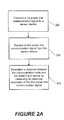
Referring now to FIGS. 2A-2H, flowcharts are provided illustrating operations of a communication node C of FIGS. 1A-1E, according to various embodiments. Referring to FIG. 2A, operations of the communication node C may include transmitting (Block 201) a first power line communication signal P from the communication node C to a sensor device S that is at or adjacent an electric grid device E. The operations may include receiving (Block 202) from the sensor device S a second power line communication signal that is responsive to the first power line communication signal P, at the communication node C. Moreover, the operations may include determining (Block 203) a distance D between the communication node C and the electric grid device E by measuring an electrical parameter of the second power line communication signal, at the communication node C.
In some embodiments, the communication node C may measure the full waveform, rather than just the magnitude, of the second power line communication signal that is received from the sensor device S. For example, a power line carrier data collector in the communication node C may sample the full waveform of the second power line communication signal.
Referring to FIG. 2B, operations of transmitting (Block 201) the first power line communication signal P may include transmitting (Block 201B) the first power line communication signal P using a Mid Voltage (MV) electric distribution network corresponding to voltages between about 4,000 Volts and about 69,000 Volts. Moreover, operations of receiving (Block 202) the second power line communication signal may include receiving (Block 202B) the second power line communication signal using the Mid Voltage (MV) electric distribution network corresponding to voltages between about 4,000 Volts and about 69,000 Volts.
Referring to FIG. 2C, it will be understood that the first power line communication signal P may be a Power Line Carrier (PLC) signal or a Broadband over Power Lines (BPL) signal (Block 201C), Accordingly, the PLC pings P illustrated in FIGS. 1A and 1B may alternatively be BPL pings. Moreover, referring again to FIG. 2C, which is a modification of FIG. 2B, the second power line communication signal may be a PLC signal or a BPL signal ( Blocks 202C, 203C).
Referring to FIG. 2D, the operations of FIG. 2A may also include transmitting (Block 204), from the communication node C to an electric utility head end system H (or to a higher-tier communication node C), a value representing the distance D, via the communication network 115 (e.g., a local area network or a Wide Area Network). The communication node C may also transmit its own GPS location data to the electric utility head end system H. Accordingly, the electric utility head end system H may use the communication node C's GPS location data and the value representing the distance D to determine the position of the electric grid device E. For example, if the electric utility head end system H has GPS location data and values representing distances D from at least three communication nodes C, then the electric utility head end system H may triangulate the position of the electric grid device E.
Referring to FIG. 2E, operations of determining (Block 203) the distance D between the communication node C and the electric grid device E by measuring the electrical parameter of second power line communication signal at the communication node may include determining (Block 203E) the distance D between the communication node C and the electric grid device E by measuring an impedance Z corresponding to the second power line communication signal, at the communication node C. For example, the impedance Z may be the impedance experienced by the second power line communication signal when traveling the distance D to the communication node C. Accordingly, the impedance Z may be determined at the communication node C in the field (i.e., closer to the electric grid device E) rather than at a more central location such as the electric utility data center 130 (or even a substation). Moreover, the measurement/determination of the impedance Z at the communication node C may be performed using a second PLC signal from the sensor device S that is responsive to a first PLC signal from the communication node C.
Referring to FIG. 2F, the operations of FIG. 2A may also include determining (Block 204F) a device type of the electric grid device E by analyzing an identification component (e.g., an identification signature) of the second power line communication signal, at the communication node C. An identification component may be, for example, a waveform or other electronic signature particular to a device's operation. As another non-limiting example, an identification component may be a pre-determined frequency tone/characteristic used to identify an asset/device. Accordingly, the communication node C may determine both a location and a device type of the electric grid device E using the second power line communication signal. Additionally or alternatively, the operations may include determining (Block 204F) whether the electric grid device E is electrically connected to an electric grid 100, by analyzing an identification component of the second power line communication signal, at the communication node C.
Referring to FIG. 2G, the operations of FIG. 2A may also include monitoring (Block 204G) a health component of the electric grid device E by analyzing an electrical signature (e.g., a health signature) and/or an electrical parameter of the second power line communication signal, at the communication node C. For example, the communication node C may perform waveform analysis of the second power line communication signal to determine asset health. As an example, the communication node C may perform waveform analysis to evaluate performance characteristics of the electric grid device E, behavioral characteristics of the electric grid device E, and/or indicators of aging of the electric grid device E.
Referring to FIGS. 1A and 2H, it will be understood that transmitting (Block 201) the first power line communication signal P may include transmitting (Block 201H) an unsolicited ping P from the communication node C to a first sensor device S1 that is at or adjacent a first electric grid device E1 and to a second sensor device S2 that is at or adjacent a second electric grid device E2. In other words, the ping P may be transmitted from the communication node C to the first and second sensor devices S1, S2 without any requests/prompting by either of the first and second sensor devices S1, S2. Accordingly, in some embodiments, the communication node C may periodically transmit the unsolicited ping P after a pre-determined time interval, irrespective of whether the communication node C has received signals from the first and second sensor devices S1, S2. The unsolicited ping P may therefore be helpful in locating recently-added (or recently-relocated) electric grid devices E.
Moreover, referring still to FIG. 2H, the communication node C may receive (Block 202H) from the second sensor device S2 a third power line communication signal that is responsive to the unsolicited ping P, in addition to receiving from the first sensor device S1 the second power line communication signal (which is also responsive to the unsolicited ping P). Operations of the communication node C may also include determining (Block 203H) first and second distances D1, D2 between the communication node C and the first and second electric grid devices E1, E2, respectively, by measuring first and second electrical parameters of the second and third power line communication signals, respectively.
It will be understood that a communication node of FIG. 1C or 1E may be configured to perform the operations illustrated in FIGS. 2A-2H. For example, a power line communications interface 163 of the communication node C may be configured to perform the transmit and receive operations illustrated in FIGS. 2A-2H. Moreover, a processor 150 and/or a processor 150′ of the communication node C may be configured to perform the measurements/determinations/analyses illustrated in FIGS. 2A-2H.
Referring now to FIGS. 3A-3G, flowcharts are provided illustrating operations of a sensor device S of FIGS. 1A, 1B, and 1F, according to various embodiments. Referring to FIG. 3A, operations of a sensor device S that is at or adjacent an electric grid device E may include receiving (Block 301) from a communication node C a first power line communication signal P at the sensor device S that is at or adjacent the electric grid device E. Moreover, the operations may include transmitting (Block 302) a second power line communication signal from the sensor device S to the communication node C, in response to receiving the first power line communication signal P. The second power line communication signal may include an electrical parameter (e.g., characteristic) corresponding to a distance D between the communication node C and the electric grid device E.
Referring to FIG. 3B, operations of receiving (Block 301) the first power line communication signal P may include receiving (Block 301B) the first power line communication signal P using a Mid Voltage (MV) electric distribution network corresponding to voltages between about 4,000 Volts and about 69,000 Volts. Moreover, operations of transmitting (Block 302) the second power line communication signal may include transmitting (Block 302B) the second power line communication signal using the Mid Voltage (MV) electric distribution network corresponding to voltages between about 4,000 Volts and about 69,000 Volts.
Referring to FIG. 3C, which is a modification of FIG. 3B, it will be understood that the first power line communication signal P may include a Power Line Carrier (PLC) signal or a Broadband over Power Lines (BPL) signal (Block 301C). Moreover, the second power line communication signal may also include a PLC signal or a BPL signal (Block 302C).
Referring to FIG. 3D, which is a modification of FIG. 3A, the electrical parameter (e.g., characteristic) corresponding to a distance D between the communication node C and the electric grid device E may be an impedance Z corresponding to the second power line communication signal (Block 302D).
Referring to FIG. 3E, which is a modification of FIG. 3A, the second power line communication signal may include an identification component (e.g., an identification signature) corresponding to a device type of the electric grid device E, in some embodiments. Moreover, transmitting (Block 302) the second power line communication signal may include transmitting (Block 302E) the second power line communication signal including the identification component corresponding to the device type of the electric grid device E, from the sensor device S to the communication node C, in response to receiving the first power line communication signal P. In other words, the sensor device S may return a particular tone or answer based on the grid asset it is installed at/next to.
Additionally or alternatively, referring to still to FIG. 3E, the second power line communication signal may include an identification component corresponding to whether the electric grid device E is electrically connected to an electric grid 100. Moreover, transmitting (Block 302) the second power line communication signal may include transmitting (Block 302E) the second power line communication signal including the identification component corresponding to whether the electric grid device E is electrically connected to the electric grid 100, from the sensor device S to the communication node C, in response to receiving the first power line communication signal P.
Referring to FIG. 3F, which is a modification of FIG. 3A, the second power line communication signal may include an electrical signature (e.g., health signature) and/or an electrical parameter corresponding to a health component of the electric grid device E. Moreover, transmitting (Block 302) the second power line communication signal may include transmitting (Block 302F) the second power line communication signal including the electrical signature and/or electrical parameter corresponding to the health component of the electric grid device E, from the sensor device S to the communication node C, in response to receiving the first power line communication signal P.
Referring to FIG. 3G, which is a modification of FIG. 3A, the first power line communication signal P may include an unsolicited ping P transmitted by the communication node C. Moreover, receiving (Block 301) the first power line communication signal P may include receiving (Block 301G) from the communication node C the unsolicited ping P at the sensor device S that is at or adjacent the electric grid device E.
It will be understood that a sensor device S of FIG. 1F may be configured to perform the operations illustrated in FIGS. 3A-3G. For example, a power line communications interface 163′ of the sensor device S may be configured to perform the transmit and receive operations illustrated in FIGS. 3A-3G.
According to various embodiments described herein, a communication node C may send an MV PLC signal to a sonar sensor (e.g., a sensor device S). The communication node C may then analyze a responsive signal that it receives to determine, for example, (a) an impedance measurement, (b) a signature regarding device/asset (e.g., an electric grid device E) health, (c) a signature regarding a device/asset type, and/or (d) a signature regarding whether the device/asset is electrically connected to a grid. Because having a built-in GPS at the device/asset may be cost-prohibitive, the communication node C may perform the impedance measurement to determine a distance between the device/asset and the communication node C. Moreover, software of a head end system H may take (i) a GPS measurement of the communication node C and (ii) the impedance measurement by the communication node C to determine GIS coordinates for the device/asset. Accordingly, PLC and waveform analysis tools can be used at the communication node C to help determine the geospatial relationship of grid devices/assets and/or to monitor and improve grid device/asset health. In contrast, analysis/calculations performed exclusively at the electric utility data center 130, without using the communication node C that is in the field and thus closer to the grid device/asset, may be slower and less accurate.
In the specification, various embodiments of the present inventive concepts have been disclosed and, although specific terms are employed, they are used in a generic and descriptive sense only and not for purposes of limitation. Those skilled in the art will readily appreciate that many modifications are possible for the disclosed embodiments without materially departing from the teachings and advantages of the present inventive concepts. The present inventive concepts are defined by the following claims, with equivalents of the claims to be included therein.

Claims (18)

What is claimed is:
1. A method of operating a communication node, the method comprising:
transmitting, using a Mid Voltage (MV) electric distribution network corresponding to voltages between about 4,000 Volts and about 69,000 Volts, a first power line communication signal from the communication node to a sensor device that is at or adjacent an electric grid device;
receiving, using the Mid Voltage (MV) electric distribution network corresponding to voltages between about 4,000 Volts and about 69,000 Volts, from the sensor device a second power line communication signal that is responsive to the first power line communication signal, at the communication node;
determining a distance between the communication node and the electric grid device by measuring an electrical parameter of the second power line communication signal, at the communication node; and
transmitting, from the communication node to an electric utility head end system, a value representing the distance, via a local area network or a wide area network,
wherein the electric utility head end system determines coordinates for the electric grid device by using (i) a GPS measurement of the communication node and (ii) the value representing the distance between the communication node and the electric grid device, and
wherein the electric grid device is on a distribution line.
2. The method of claim 1, wherein the first power line communication signal comprises a Power Line Carrier (PLC) signal or a Broadband over Power Lines (BPL) signal.
3. The method of claim 1, wherein determining the distance between the communication node and the electric grid device by measuring the electrical parameter of second power line communication signal at the communication node comprises:
determining the distance between the communication node and the electric grid device by measuring an impedance corresponding to the second power line communication signal, at the communication node.
4. The method of claim 1, further comprising determining whether the electric grid device is electrically connected to an electric grid, by analyzing an identification component of the second power line communication signal, at the communication node.
5. The method of claim 1, further comprising monitoring a health component of the electric grid device by analyzing an electrical signature and/or an electrical parameter of the second power line communication signal, at the communication node.
6. The method of claim 1, wherein:
the sensor device comprises a first sensor device;
the electric grid device comprises a first electric grid device;
transmitting the first power line communication signal comprises transmitting an unsolicited ping from the communication node to the first sensor device and to a second sensor device that is at or adjacent a second electric grid device;
the distance comprises a first distance;
the electrical parameter comprises a first electrical parameter; and
the method further comprises:
receiving from the second sensor device a third power line communication signal that is responsive to the unsolicited ping, at the communication node; and
determining a second distance between the communication node and the second electric grid device by measuring a second electrical parameter of the third power line communication signal, at the communication node.
7. The method of claim 1, further comprising determining a device type of the electric grid device by analyzing an identification component of the second power line communication signal, at the communication node.
8. The method of claim 7, wherein the identification component of the second power line communication signal comprises a waveform or other electronic signature particular to an operation of the electric grid device.
9. A communication node, comprising:
a power line communications interface configured to:
transmit, using a Mid Voltage (MV) electric distribution network corresponding to voltages between about 4,000 Volts and about 69,000 Volts, a first power line communication signal from the communication node to a sensor device that is at or adjacent an electric grid device; and
receive, using the Mid Voltage (MV) electric distribution network corresponding to voltages between about 4,000 Volts and about 69,000 Volts, from the sensor device a second power line communication signal that is responsive to the first power line communication signal;
a processor, wherein the processor is configured to determine a distance between the communication node and the electric grid device by measuring an electrical parameter of the second power line communication signal at the communication node; and
a network interface configured to transmit, from the communication node to an electric utility head end system, a value representing the distance, via a local area network or a wide area network,
wherein the electric utility head end system determines coordinates for the electric grid device by using (i) a GPS measurement of the communication node and (ii) the value representing the distance between the communication node and the electric grid device, and
wherein the electric grid device comprises a field asset on a distribution line.
10. The communication node of claim 9, further comprising a polling device that comprises at least one of the power line communications interface and the processor.
11. The communication node of claim 9, wherein the first power line communication signal comprises a Power Line Carrier (PLC) signal or a Broadband over Power Lines (BPL) signal.
12. The communication node of claim 9, wherein:
the electrical parameter comprises an impedance; and
the processor is configured to determine the distance between the communication node and the electric grid device by using the impedance of the second power line communication signal.
13. The communication node of claim 9, wherein an identification component of the second power line communication signal comprises a waveform or other electronic signature particular to an operation of the electric grid device.
14. The communication node of claim 9, wherein the processor is further configured to determine whether the electric grid device is electrically connected to an electric grid, by analyzing an identification component of the second power line communication signal.
15. The communication node of claim 9, wherein the processor is further configured to monitor a health component of the electric grid device by analyzing an electrical signature and/or an electrical parameter of the second power line communication signal.
16. The communication node of claim 9, wherein:
the sensor device comprises a first sensor device;
the electric grid device comprises a first electric grid device; and
the power line communications interface is configured to transmit the first power line communication signal as an unsolicited ping to the first sensor device and to a second sensor device that is at or adjacent a second electric grid device;
the distance comprises a first distance;
the electrical parameter comprises a first electrical parameter;
the power line communications interface is configured to receive from the second sensor device a third power line communication signal that is responsive to the unsolicited ping; and
the processor is configured to determine a second distance between the communication node and the second electric grid device by measuring a second electrical parameter of the third power line communication signal.
17. The communication node of claim 9, wherein the field asset comprises a capacitor bank, regulator, recloser, line switch, fuse, street light, or transformer on the distribution line.
18. A method of operating a communication node located in a field of a power grid of an electric utility, the method comprising:
transmitting a first power line communication signal from the communication node in the field to a sensor device that is at or adjacent a field asset on a distribution line of the power grid;
receiving from the sensor device a second power line communication signal that is responsive to the first power line communication signal, at the communication node in the field;
determining a distance between the communication node in the field and the field asset that is on the distribution line by measuring an electrical parameter of the second power line communication signal, at the communication node in the field; and
transmitting, from the communication node to an electric utility head end system, a value representing the distance, via a local area network or a wide area network,
wherein the electric utility head end system determines coordinates for the field asset by using (i) a GPS measurement of the communication node and (ii) the value representing the distance between the communication node and the field asset.
US14/270,914 2013-12-23 2014-05-06 Communication nodes and sensor devices configured to use power line communication signals, and related methods of operation Active 2034-09-27 US9722665B2 (en)

Priority Applications (1)

Application Number Priority Date Filing Date Title
US14/270,914 US9722665B2 (en) 2013-12-23 2014-05-06 Communication nodes and sensor devices configured to use power line communication signals, and related methods of operation

Applications Claiming Priority (2)

Application Number Priority Date Filing Date Title
US201361919993P 2013-12-23 2013-12-23
US14/270,914 US9722665B2 (en) 2013-12-23 2014-05-06 Communication nodes and sensor devices configured to use power line communication signals, and related methods of operation

Publications (2)

Publication Number Publication Date
US20150180282A1 US20150180282A1 (en) 2015-06-25
US9722665B2 true US9722665B2 (en) 2017-08-01

Family

ID=53401180

Family Applications (2)

Application Number Title Priority Date Filing Date
US14/270,914 Active 2034-09-27 US9722665B2 (en) 2013-12-23 2014-05-06 Communication nodes and sensor devices configured to use power line communication signals, and related methods of operation
US14/270,982 Active US9407324B2 (en) 2013-12-23 2014-05-06 Communication nodes and sensor devices configured to use power line communication signals, and related methods of operation

Family Applications After (1)

Application Number Title Priority Date Filing Date
US14/270,982 Active US9407324B2 (en) 2013-12-23 2014-05-06 Communication nodes and sensor devices configured to use power line communication signals, and related methods of operation

Country Status (1)

Country Link
US (2) US9722665B2 (en)

Families Citing this family (21)

* Cited by examiner, † Cited by third party
Publication number Priority date Publication date Assignee Title
US11140798B2 (en) * 2014-11-19 2021-10-05 Schroff Technologies International, Inc. Ventilation control apparatus and method
US9652723B2 (en) 2015-06-05 2017-05-16 Sas Institute Inc. Electrical transformer failure prediction
US10991169B2 (en) * 2015-08-20 2021-04-27 Schneider Electric Industries Sas Method for determining a mean time to failure of an electrical device
CN105242178A (en) * 2015-10-28 2016-01-13 河南开启电力实业有限公司 On-line low-voltage distribution line monitoring system
US11627199B2 (en) * 2016-01-05 2023-04-11 Schneider Electric USA, Inc. System and methods for creating a geospatial network model in a client environment
EP3190528A3 (en) 2016-01-05 2017-07-26 Schneider Electric USA, Inc. System and methods for creating and managing geospatial network model in a client environment
US10979311B2 (en) 2016-01-05 2021-04-13 Schneider Electric USA, Inc. System and method for validating network configuration changes in a client environment
US11017131B2 (en) 2016-01-19 2021-05-25 Schneider Electric USA, Inc. System and methods for optimizing distribution network designs in real-time
DE112017003157T5 (en) * 2016-06-22 2019-03-14 Soraa, Inc. Intelligent modules for intelligent networks
US11394426B2 (en) 2016-06-22 2022-07-19 Korrus, Inc. Intelligent modules for intelligent networks
US10044410B1 (en) 2017-04-18 2018-08-07 Simmonds Precision Products, Inc. Rotorcraft tail boom health management system
CN107248962B (en) * 2017-05-25 2020-08-04 中国能源建设集团广东省电力设计研究院有限公司 Communication switching method and device for power grid information acquisition
US10666230B2 (en) * 2017-08-29 2020-05-26 Intel Corporation Variable impedance communication terminal
CN107493208A (en) * 2017-08-30 2017-12-19 苏州朗动网络科技有限公司 Full the link performance monitoring method and system of a kind of medium-and-large-sized operation system
US11143758B2 (en) * 2017-10-13 2021-10-12 Navico Holding As Sonar transducer performance optimization
US10541725B1 (en) * 2017-12-15 2020-01-21 The Boeing Company Method and apparatus for physical security over a power line connection
CN108763256A (en) * 2018-03-30 2018-11-06 云南电网有限责任公司信息中心 A kind of electric power GIS Temporal Model construction method based on Dike-pond modes
US11055651B2 (en) 2018-12-13 2021-07-06 Schneider Electric USA, Inc. Systems and methods for visualization of flow direction in a distribution network
US11323435B2 (en) 2019-05-08 2022-05-03 The Boeing Company Method and apparatus for advanced security systems over a power line connection
CN112818076A (en) * 2021-02-05 2021-05-18 河南红飒科技发展有限公司 Asset statistical method based on GIS
CN116566439B (en) * 2023-07-06 2023-11-14 北京智芯半导体科技有限公司 HPLC network optimization method, device, electronic equipment and storage medium

Citations (41)

* Cited by examiner, † Cited by third party
Publication number Priority date Publication date Assignee Title
US4689752A (en) 1983-04-13 1987-08-25 Niagara Mohawk Power Corporation System and apparatus for monitoring and control of a bulk electric power delivery system
US5341372A (en) 1991-04-10 1994-08-23 California Institute Of Technology Protocol for multiple node network
US5495239A (en) 1994-08-02 1996-02-27 General Electric Company Method and apparatus for communicating with a plurality of electrical metering devices and a system control center with a mobile node
US6327541B1 (en) 1998-06-30 2001-12-04 Ameren Corporation Electronic energy management system
US6509841B1 (en) 1997-10-16 2003-01-21 Cic Global, Llc System and method for communication between remote locations
US20030079613A1 (en) * 2001-11-01 2003-05-01 Williamson Charles G. Intelligent coffeemaker appliance
US20050172056A1 (en) * 2004-02-02 2005-08-04 Samsung Electronics Co., Ltd. Bridging apparatus and method for enabling a UPnP device to control a PLC device
US7117105B2 (en) 2002-02-25 2006-10-03 General Electric Company Method and apparatus for ground fault protection
US7126494B2 (en) 1997-02-12 2006-10-24 Elster Electricity, Llc Remote access to electronic meters using a TCP/IP protocol suite
US7251570B2 (en) 2003-07-18 2007-07-31 Power Measurement Ltd. Data integrity in a mesh network
US20080052253A1 (en) 2006-08-28 2008-02-28 Emeter Corporation System and method for message-bus-based advanced meter information system
US20080070504A1 (en) * 2006-09-18 2008-03-20 Infineon Technologies Ag Communication terminal device
US7415725B2 (en) 2002-08-29 2008-08-19 Power Measurement Ltd. Multi-function intelligent electronic device with secure access
US20080258903A1 (en) * 2007-04-22 2008-10-23 Kevin Le Multifunctional Powerline Sensor Network
US20080260010A1 (en) 2004-10-04 2008-10-23 Sony Deutschland Gmbh Power Line Communication Methods and Devices
US20090002137A1 (en) * 2007-06-26 2009-01-01 Radtke William O Power Line Coupling Device and Method
US7558703B2 (en) 2006-11-01 2009-07-07 Abb Research Ltd. Electrical substation monitoring and diagnostics
US20090281674A1 (en) 2008-05-09 2009-11-12 Taft Jeffrey D Method and system for managing a power grid
US7764943B2 (en) 2006-03-27 2010-07-27 Current Technologies, Llc Overhead and underground power line communication system and method using a bypass
US20100299517A1 (en) * 2009-05-22 2010-11-25 Nuvon, Inc. Network System with a Plurality of Networked Devices with Various Connection Protocols
US7945401B2 (en) 2008-06-30 2011-05-17 International Business Machines Corporation Distributed intelligent remote terminal units
WO2011076242A1 (en) 2009-12-21 2011-06-30 Siemens Aktiengesellschaft Expanded power automation system
US20120029710A1 (en) 2010-07-30 2012-02-02 Ruchali Dodderi Intelligent core engine
US20120054397A1 (en) 2010-08-25 2012-03-01 Smartsynch, Inc. Interface bus for utility-grade network communication devices
US8135550B2 (en) 2008-12-09 2012-03-13 Consolidated Edison Company Of New York, Inc. System for monitoring and assessing electrical circuits and method of operation
US20120119577A1 (en) * 2010-11-17 2012-05-17 International Business Machines Corporation Smart Power Sockets, Boards, and Plugs
US8198998B1 (en) * 2008-01-23 2012-06-12 Adaptive Networks, Inc. Identification of power line locations by power line signatures
US20120166610A1 (en) 2010-12-23 2012-06-28 Electronics And Telecommunications Research Institute Method and system for communication in application field
US20120184279A1 (en) * 2011-01-17 2012-07-19 Urs-Viktor Marti Generating a network map
US20120217803A1 (en) 2009-06-15 2012-08-30 Google Inc. Supplying grid ancillary services using controllable loads
US20120265586A1 (en) * 2010-09-16 2012-10-18 Rutgers, The State University Of New Jersey System and method to measure and control power consumption in a residential or commercial building via a wall socket to ensure optimum energy usage therein
US20120300860A1 (en) 2010-08-24 2012-11-29 Sony Corporation Transmission device, reception device, and communication system
US20130024149A1 (en) 2011-07-21 2013-01-24 Cisco Technology, Inc. Identification of electrical grid phase information for end-points in a grid network
US20130110296A1 (en) 2011-10-19 2013-05-02 Zeco Systems Pte Ltd Methods and Apparatuses for Charging of Electric Vehicles
US20130154667A1 (en) * 2011-12-15 2013-06-20 Dr. Ing. H.C.F. Porsche Aktiengesellschaft Detection of charging cable
US20140146899A1 (en) 2012-11-23 2014-05-29 Plc Soft Holding Method and apparatus for data communications over power lines
US20140191582A1 (en) * 2013-01-08 2014-07-10 Infineon Technologies Austria Ag Power Converter Circuit with AC Output and at Least One Transformer
US20140210449A1 (en) 2011-08-30 2014-07-31 Toyota Jidosha Kabushiki Kaishi Method for identifying operating mode of charging/supplying system between vehicle and exterior, and system for identifying operating mode of the system by the identifying method
US20140269860A1 (en) * 2013-03-15 2014-09-18 Dockon Ag Adaptive line equalizer for improving data communication over less than perfect power lines or transmission lines
US20150016159A1 (en) * 2013-07-12 2015-01-15 Infineon Technologies Austria Ag Multiphase Power Converter Circuit and Method
US20150036685A1 (en) * 2013-07-30 2015-02-05 Cisco Technology, Inc. Multicast label distribution protocol over a remote loop-free alternative

Patent Citations (41)

* Cited by examiner, † Cited by third party
Publication number Priority date Publication date Assignee Title
US4689752A (en) 1983-04-13 1987-08-25 Niagara Mohawk Power Corporation System and apparatus for monitoring and control of a bulk electric power delivery system
US5341372A (en) 1991-04-10 1994-08-23 California Institute Of Technology Protocol for multiple node network
US5495239A (en) 1994-08-02 1996-02-27 General Electric Company Method and apparatus for communicating with a plurality of electrical metering devices and a system control center with a mobile node
US7126494B2 (en) 1997-02-12 2006-10-24 Elster Electricity, Llc Remote access to electronic meters using a TCP/IP protocol suite
US6509841B1 (en) 1997-10-16 2003-01-21 Cic Global, Llc System and method for communication between remote locations
US6327541B1 (en) 1998-06-30 2001-12-04 Ameren Corporation Electronic energy management system
US20030079613A1 (en) * 2001-11-01 2003-05-01 Williamson Charles G. Intelligent coffeemaker appliance
US7117105B2 (en) 2002-02-25 2006-10-03 General Electric Company Method and apparatus for ground fault protection
US7415725B2 (en) 2002-08-29 2008-08-19 Power Measurement Ltd. Multi-function intelligent electronic device with secure access
US7251570B2 (en) 2003-07-18 2007-07-31 Power Measurement Ltd. Data integrity in a mesh network
US20050172056A1 (en) * 2004-02-02 2005-08-04 Samsung Electronics Co., Ltd. Bridging apparatus and method for enabling a UPnP device to control a PLC device
US20080260010A1 (en) 2004-10-04 2008-10-23 Sony Deutschland Gmbh Power Line Communication Methods and Devices
US7764943B2 (en) 2006-03-27 2010-07-27 Current Technologies, Llc Overhead and underground power line communication system and method using a bypass
US20080052253A1 (en) 2006-08-28 2008-02-28 Emeter Corporation System and method for message-bus-based advanced meter information system
US20080070504A1 (en) * 2006-09-18 2008-03-20 Infineon Technologies Ag Communication terminal device
US7558703B2 (en) 2006-11-01 2009-07-07 Abb Research Ltd. Electrical substation monitoring and diagnostics
US20080258903A1 (en) * 2007-04-22 2008-10-23 Kevin Le Multifunctional Powerline Sensor Network
US20090002137A1 (en) * 2007-06-26 2009-01-01 Radtke William O Power Line Coupling Device and Method
US8198998B1 (en) * 2008-01-23 2012-06-12 Adaptive Networks, Inc. Identification of power line locations by power line signatures
US20090281674A1 (en) 2008-05-09 2009-11-12 Taft Jeffrey D Method and system for managing a power grid
US7945401B2 (en) 2008-06-30 2011-05-17 International Business Machines Corporation Distributed intelligent remote terminal units
US8135550B2 (en) 2008-12-09 2012-03-13 Consolidated Edison Company Of New York, Inc. System for monitoring and assessing electrical circuits and method of operation
US20100299517A1 (en) * 2009-05-22 2010-11-25 Nuvon, Inc. Network System with a Plurality of Networked Devices with Various Connection Protocols
US20120217803A1 (en) 2009-06-15 2012-08-30 Google Inc. Supplying grid ancillary services using controllable loads
WO2011076242A1 (en) 2009-12-21 2011-06-30 Siemens Aktiengesellschaft Expanded power automation system
US20120029710A1 (en) 2010-07-30 2012-02-02 Ruchali Dodderi Intelligent core engine
US20120300860A1 (en) 2010-08-24 2012-11-29 Sony Corporation Transmission device, reception device, and communication system
US20120054397A1 (en) 2010-08-25 2012-03-01 Smartsynch, Inc. Interface bus for utility-grade network communication devices
US20120265586A1 (en) * 2010-09-16 2012-10-18 Rutgers, The State University Of New Jersey System and method to measure and control power consumption in a residential or commercial building via a wall socket to ensure optimum energy usage therein
US20120119577A1 (en) * 2010-11-17 2012-05-17 International Business Machines Corporation Smart Power Sockets, Boards, and Plugs
US20120166610A1 (en) 2010-12-23 2012-06-28 Electronics And Telecommunications Research Institute Method and system for communication in application field
US20120184279A1 (en) * 2011-01-17 2012-07-19 Urs-Viktor Marti Generating a network map
US20130024149A1 (en) 2011-07-21 2013-01-24 Cisco Technology, Inc. Identification of electrical grid phase information for end-points in a grid network
US20140210449A1 (en) 2011-08-30 2014-07-31 Toyota Jidosha Kabushiki Kaishi Method for identifying operating mode of charging/supplying system between vehicle and exterior, and system for identifying operating mode of the system by the identifying method
US20130110296A1 (en) 2011-10-19 2013-05-02 Zeco Systems Pte Ltd Methods and Apparatuses for Charging of Electric Vehicles
US20130154667A1 (en) * 2011-12-15 2013-06-20 Dr. Ing. H.C.F. Porsche Aktiengesellschaft Detection of charging cable
US20140146899A1 (en) 2012-11-23 2014-05-29 Plc Soft Holding Method and apparatus for data communications over power lines
US20140191582A1 (en) * 2013-01-08 2014-07-10 Infineon Technologies Austria Ag Power Converter Circuit with AC Output and at Least One Transformer
US20140269860A1 (en) * 2013-03-15 2014-09-18 Dockon Ag Adaptive line equalizer for improving data communication over less than perfect power lines or transmission lines
US20150016159A1 (en) * 2013-07-12 2015-01-15 Infineon Technologies Austria Ag Multiphase Power Converter Circuit and Method
US20150036685A1 (en) * 2013-07-30 2015-02-05 Cisco Technology, Inc. Multicast label distribution protocol over a remote loop-free alternative

Non-Patent Citations (2)

* Cited by examiner, † Cited by third party
Title
Abelsen et al., "Adaptive Information Flow Mechanisms and Management for Power Grid Contingencies", Washington State University School of Electrical Engineering and Computer Science, Pullman, Washington, USA, 2007.
Huang et al., "A Study of Publish/Subscribe Systems for Real-Time Grid Monitoring", Parallel and Distributed Processing Symposium, Mar. 26-30, 2007, IPDPS 2007, pp. 1-8.

Also Published As

Publication number Publication date
US20150180538A1 (en) 2015-06-25
US9407324B2 (en) 2016-08-02
US20150180282A1 (en) 2015-06-25

Similar Documents

Publication Publication Date Title
US9722665B2 (en) Communication nodes and sensor devices configured to use power line communication signals, and related methods of operation
EP2540017B1 (en) Methods and apparatus for time synchronization and measurement of power distribution systems
EP2508897B1 (en) Power consumption measurement system, outlet device, control device, measuring device, and power consumption measuring method
US8781768B2 (en) Data reduction in a multi-node system
US20130064178A1 (en) System For Monitoring Electrical Power Distribution Lines In A Power Grid Using A Wireless Sensor Network
US10794939B2 (en) Sensors for power distribution network and electrical grid monitoring system associated therewith
US20120062390A1 (en) Locating Utility Metering Devices
US9778286B2 (en) Sensors for power distribution network and electrical grid monitoring system associated therewith
US9742644B2 (en) Verification of connection of meters to network
US11646602B2 (en) Topology and phase detection for electrical supply network
EP2660564A1 (en) Verification of connection of meters to network
CN111512168B (en) System and method for analyzing fault data of a power transmission network
CN110995785A (en) Low-voltage distribution network cloud platform based on Internet of things
US20220260616A1 (en) Multichannel electrical power grid monitoring system for detecting and analyzing sensor installation and configuration errors
EP3449267A1 (en) A method for identifying the phases of a multi-phase distribution grid
US20150205317A1 (en) Power distribution management apparatus and abnormality detection method
US10333300B2 (en) Power distribution management apparatus, power distribution management method, and recording medium
Nordman An architecture for wireless sensors in distributed management of electrical distribution systems
WO2017002020A1 (en) System and method for detecting a fault in an overhead power line
JP6328353B1 (en) Phase group estimation device, phase group estimation method, and phase group estimation program
KR101396946B1 (en) Remote meter reading method and apparatus
US9835659B2 (en) Power distribution management method, voltage determination method, and recording medium for determining transmission voltage of substation
CN109922429A (en) A kind of network struction device of intelligent electric meter
CN106483398A (en) The apparatus and method of measurement data in high-voltage direct current
US20230050693A1 (en) Partitioning assets for electric grid connection mapping

Legal Events

Date Code Title Description
AS Assignment

Owner name: DUKE ENERGY CORPORATION, NORTH CAROLINA

Free format text: ASSIGNMENT OF ASSIGNORS INTEREST;ASSIGNORS:SMITH, RAIFORD;LAVAL, STUART;HANDLEY, JASON;REEL/FRAME:032832/0452

Effective date: 20140502

AS Assignment

Owner name: DUKE ENERGY CORPORATION, NORTH CAROLINA

Free format text: CORRECTIVE ASSIGNMENT TO CORRECT THE ASSIGNMENT DOCUMENT WHEREAS, DUKE ENERGY CORPORATION, A NORTH CAROLINA CORPORATION PREVIOUSLY RECORDED ON REEL 032832 FRAME 0452. ASSIGNOR(S) HEREBY CONFIRMS THE ASSIGNMENT DOCUMENT HAS BEEN CORRECTED TO READ -- WHEREAS, DUKE ENERGY CORPORATION, A DELAWARE CORPORATION --;ASSIGNORS:SMITH, RAIFORD;LAVAL, STUART;HANDLEY, JASON;REEL/FRAME:035433/0001

Effective date: 20140502

Owner name: DUKE ENERGY CORPORATION, NORTH CAROLINA

Free format text: CORRECTIVE ASSIGNMENT TO CORRECT THE ASSIGNMENT DOCUMENT ?WHEREAS, DUKE ENERGY CORPORATION, A NORTH CAROLINA CORPORATION?? PREVIOUSLY RECORDED ON REEL 032832 FRAME 0452. ASSIGNOR(S) HEREBY CONFIRMS THE ASSIGNMENT DOCUMENT HAS BEEN CORRECTED TO READ -- WHEREAS, DUKE ENERGY CORPORATION, A DELAWARE CORPORATION?? --;ASSIGNORS:SMITH, RAIFORD;LAVAL, STUART;HANDLEY, JASON;REEL/FRAME:035433/0001

Effective date: 20140502

STCF Information on status: patent grant

Free format text: PATENTED CASE

MAFP Maintenance fee payment

Free format text: PAYMENT OF MAINTENANCE FEE, 4TH YEAR, LARGE ENTITY (ORIGINAL EVENT CODE: M1551); ENTITY STATUS OF PATENT OWNER: LARGE ENTITY

Year of fee payment: 4